1998 OPEL FRONTERA warning light
[x] Cancel search: warning lightPage 3186 of 6000
METER AND GAUGE8E–9
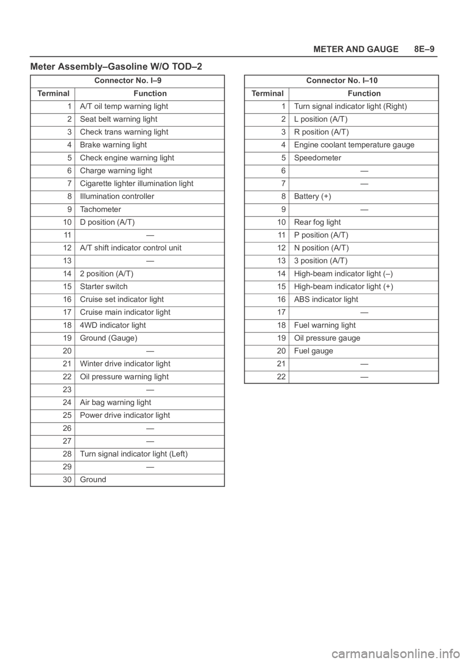
Meter Assembly–Gasoline W/O TOD–2
Connector No. I–9
Te r m i n a lFunction
1A/T oil temp warning light
2Seat belt warning light
3Check trans warning light
4Brake warning light
5Check engine warning light
6Charge warning light
7Cigarette lighter illumination light
8Illumination controller
9Tachometer
10D position (A/T)
11—
12A/T shift indicator control unit
13—
142 position (A/T)
15Starter switch
16Cruise set indicator light
17Cruise main indicator light
184WD indicator light
19Ground (Gauge)
20—
21Winter drive indicator light
22Oil pressure warning light
23—
24Air bag warning light
25Power drive indicator light
26—
27—
28Turn signal indicator light (Left)
29—
30Ground
Connector No. I–10
Te r m i n a lFunction
1Turn signal indicator light (Right)
2L position (A/T)
3R position (A/T)
4Engine coolant temperature gauge
5Speedometer
6—
7—
8Battery (+)
9—
10Rear fog light
11P position (A/T)
12N position (A/T)
133 position (A/T)
14High-beam indicator light (–)
15High-beam indicator light (+)
16ABS indicator light
17—
18Fuel warning light
19Oil pressure gauge
20Fuel gauge
21—
22—
Page 3188 of 6000
METER AND GAUGE8E–11
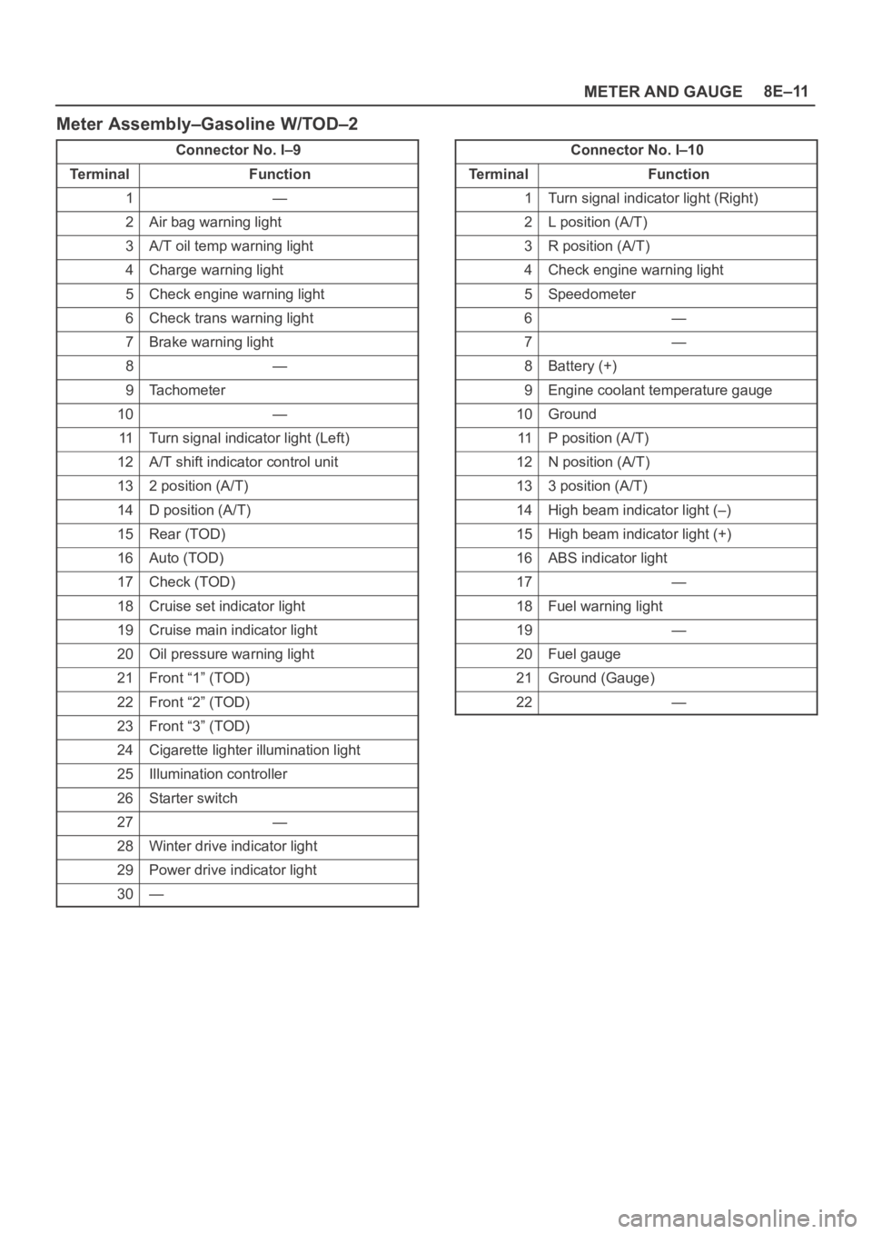
Meter Assembly–Gasoline W/TOD–2
Connector No. I–9
Te r m i n a lFunction
1—
2Air bag warning light
3A/T oil temp warning light
4Charge warning light
5Check engine warning light
6Check trans warning light
7Brake warning light
8—
9Tachometer
10—
11Turn signal indicator light (Left)
12A/T shift indicator control unit
132 position (A/T)
14D position (A/T)
15Rear (TOD)
16Auto (TOD)
17Check (TOD)
18Cruise set indicator light
19Cruise main indicator light
20Oil pressure warning light
21Front “1” (TOD)
22Front “2” (TOD)
23Front “3” (TOD)
24Cigarette lighter illumination light
25Illumination controller
26Starter switch
27—
28Winter drive indicator light
29Power drive indicator light
30—
Connector No. I–10
Te r m i n a lFunction
1Turn signal indicator light (Right)
2L position (A/T)
3R position (A/T)
4Check engine warning light
5Speedometer
6—
7—
8Battery (+)
9Engine coolant temperature gauge
10Ground
11P position (A/T)
12N position (A/T)
133 position (A/T)
14High beam indicator light (–)
15High beam indicator light (+)
16ABS indicator light
17—
18Fuel warning light
19—
20Fuel gauge
21Ground (Gauge)
22—
Page 3190 of 6000
METER AND GAUGE8E–13
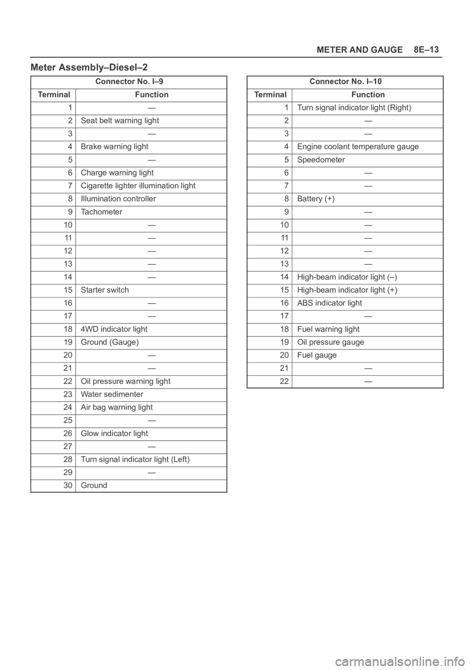
Meter Assembly–Diesel–2
Connector No. I–9
Te r m i n a lFunction
1—
2Seat belt warning light
3—
4Brake warning light
5—
6Charge warning light
7Cigarette lighter illumination light
8Illumination controller
9Tachometer
10—
11—
12—
13—
14—
15Starter switch
16—
17—
184WD indicator light
19Ground (Gauge)
20—
21—
22Oil pressure warning light
23Water sedimenter
24Air bag warning light
25—
26Glow indicator light
27—
28Turn signal indicator light (Left)
29—
30Ground
Connector No. I–10
Te r m i n a lFunction
1Turn signal indicator light (Right)
2—
3—
4Engine coolant temperature gauge
5Speedometer
6—
7—
8Battery (+)
9—
10—
11—
12—
13—
14High-beam indicator light (–)
15High-beam indicator light (+)
16ABS indicator light
17—
18Fuel warning light
19Oil pressure gauge
20Fuel gauge
21—
22—
Page 3191 of 6000
8E–14METER AND GAUGE
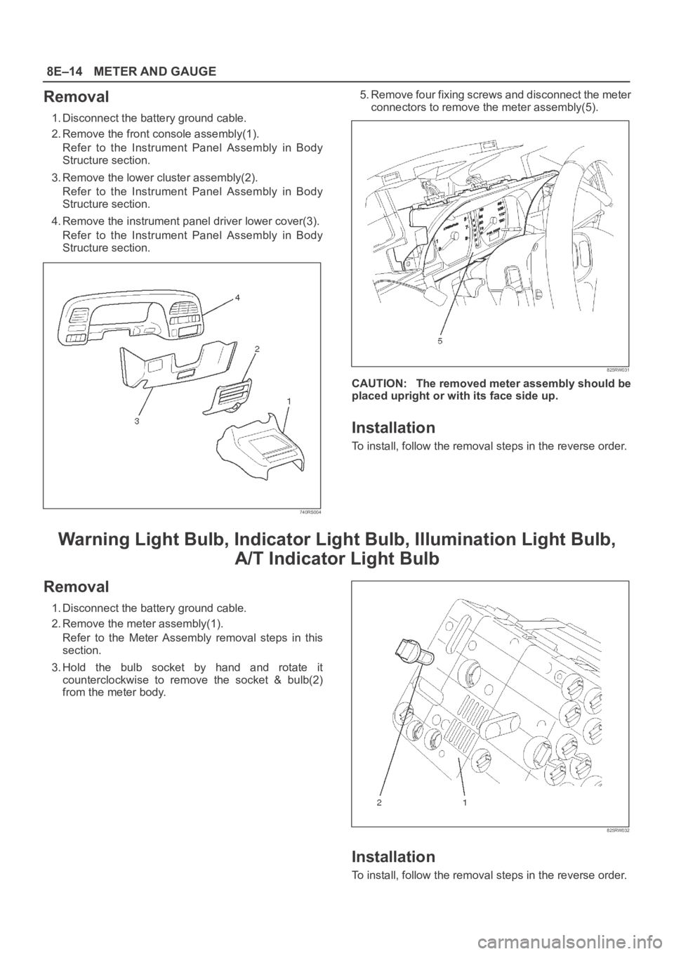
Removal
1. Disconnect the battery ground cable.
2. Remove the front console assembly(1).
Refer to the Instrument Panel Assembly in Body
Structure section.
3. Remove the lower cluster assembly(2).
Refer to the Instrument Panel Assembly in Body
Structure section.
4. Remove the instrument panel driver lower cover(3).
Refer to the Instrument Panel Assembly in Body
Structure section.
740RS004
5. Remove four fixing screws and disconnect the meter
connectors to remove the meter assembly(5).
825RW031
CAUTION: The removed meter assembly should be
placed upright or with its face side up.
Installation
To install, follow the removal steps in the reverse order.
Warning Light Bulb, Indicator Light Bulb, Illumination Light Bulb,
A/T Indicator Light Bulb
Removal
1. Disconnect the battery ground cable.
2. Remove the meter assembly(1).
Refer to the Meter Assembly removal steps in this
section.
3. Hold the bulb socket by hand and rotate it
counterclockwise to remove the socket & bulb(2)
from the meter body.
825RW032
Installation
To install, follow the removal steps in the reverse order.
Page 3361 of 6000
8H–22SECURITY AND LOCKS
Anti-theft System
General Description
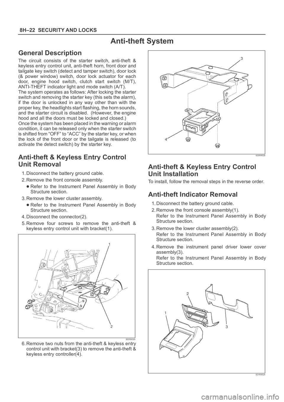
The circuit consists of the starter switch, anti-theft &
keyless entry control unit, anti-theft horn, front door and
tailgate key switch (detect and tamper switch), door lock
(& power window) switch, door lock actuator for each
door, engine hood switch, clutch start switch (M/T),
ANTI-THEFT indicator light and mode switch (A/T).
The system operates as follows: After locking the starter
switch and removing the starter key (this sets the alarm),
if the door is unlocked in any way other than with the
proper key, the headlights start flashing, the horn sounds,
and the starter circuit is disabled. (However, the engine
hood and all the doors must be locked and closed.)
Once the system has been placed in the warning or alarm
condition, it can be released only when the starter switch
is shifted from “OFF” to “ACC” by the starter key, or when
the lock of the front door or the tailgate is released (to
activate the detect switch) by the starter key.
Anti-theft & Keyless Entry Control
Unit Removal
1. Disconnect the battery ground cable.
2. Remove the front console assembly.
Refer to the Instrument Panel Assembly in Body
Structure section.
3. Remove the lower cluster assembly.
Refer to the Instrument Panel Assembly in Body
Structure section.
4. Disconnect the connector(2).
5. Remove four screws to remove the anti-theft &
keyless entry control unit with bracket(1).
825RW029
6. Remove two nuts from the anti-theft & keyless entry
control unit with bracket(3) to remove the anti-theft &
keyless entry controller(4).
825RW028
Anti-theft & Keyless Entry Control
Unit Installation
To install, follow the removal steps in the reverse order.
Anti-theft Indicator Removal
1. Disconnect the battery ground cable.
2. Remove the front console assembly(1).
Refer to the Instrument Panel Assembly in Body
Structure section.
3. Remove the lower cluster assembly(2).
Refer to the Instrument Panel Assembly in Body
Structure section.
4. Remove the instrument panel driver lower cover
assembly(3).
Refer to the Instrument Panel Assembly in Body
Structure section.
821RW024
Page 3552 of 6000
10A–1
CRUISE CONTROL SYSTEM
CONTROL SYSTEM
CRUISE CONTROL SYSTEM
CONTENTS
Service Precaution 10A–1. . . . . . . . . . . . . . . . . . . . . .
General Description 10A–1. . . . . . . . . . . . . . . . . . . . .
Diagnosis 10A–2. . . . . . . . . . . . . . . . . . . . . . . . . . . . . .
Brake Switch 10A–2. . . . . . . . . . . . . . . . . . . . . . . . . . .
Removal 10A–2. . . . . . . . . . . . . . . . . . . . . . . . . . . . .
Installation 10A–2. . . . . . . . . . . . . . . . . . . . . . . . . . . .
Adjustment 10A–3. . . . . . . . . . . . . . . . . . . . . . . . . . .
Clutch Switch 10A–3. . . . . . . . . . . . . . . . . . . . . . . . . . .
Removal and Installation 10A–3. . . . . . . . . . . . . . .
Adjustment 10A–3. . . . . . . . . . . . . . . . . . . . . . . . . . .
Starter Switch 10A–4. . . . . . . . . . . . . . . . . . . . . . . . . . .
Removal 10A–4. . . . . . . . . . . . . . . . . . . . . . . . . . . . .
Installation 10A–4. . . . . . . . . . . . . . . . . . . . . . . . . . . .
Cruise Control Main Switch 10A–5. . . . . . . . . . . . . . . Removal 10A–5. . . . . . . . . . . . . . . . . . . . . . . . . . . . .
Installation 10A–5. . . . . . . . . . . . . . . . . . . . . . . . . . . .
Cruise Control Switch (Combination Switch) 10A–5
Removal and Installation 10A–5. . . . . . . . . . . . . . .
Cruise Control Unit 10A–6. . . . . . . . . . . . . . . . . . . . . .
Removal 10A–6. . . . . . . . . . . . . . . . . . . . . . . . . . . . .
Installation 10A–6. . . . . . . . . . . . . . . . . . . . . . . . . . . .
Cruise Actuator 10A–7. . . . . . . . . . . . . . . . . . . . . . . . .
Actuator Cable Diagram (LHD) 10A–7. . . . . . . . . .
Actuator Cable Diagram (RHD) 10A–7. . . . . . . . . .
Removal 10A–8. . . . . . . . . . . . . . . . . . . . . . . . . . . . .
Installation 10A–8. . . . . . . . . . . . . . . . . . . . . . . . . . . .
Mode Switch 10A–8. . . . . . . . . . . . . . . . . . . . . . . . . . . .
Removal and Installation 10A–8. . . . . . . . . . . . . . .
Service Precaution
WARNING: IF SO EQUIPPED WITH A
SUPPLEMENTAL RESTRAINT SYSTEM (SRS),
REFER TO THE SRS COMPONENT AND WIRING
LOCATION VIEW IN ORDER TO DETERMINE
WHETHER YOU ARE PERFORMING SERVICE ON OR
NEAR THE SRS COMPONENTS OR THE SRS
WIRING. WHEN YOU ARE PERFORMING SERVICE
ON OR NEAR THE SRS COMPONENTS OR THE SRS
WIRING, REFER TO THE SRS SERVICE
INFORMATION. FAILURE TO FOLLOW WARNINGS
COULD RESULT IN POSSIBLE AIR BAG
DEPLOYMENT, PERSONAL INJURY, OR
OTHERWISE UNNEEDED SRS SYSTEM REPAIRS.
CAUTION: Always use the correct fastener in the
proper location. When you replace a fastener, use
ONLY the exact part number for that application.
ISUZU will call out those fasteners that require a
replacement after removal. ISUZU will also call out
the fasteners that require thread lockers or thread
sealant. UNLESS OTHERWISE SPECIFIED, do not
use supplemental coatings (Paints, greases, or other
corrosion inhibitors) on threaded fasteners or
fastener joint interfaces. Generally, such coatings
adversely affect the fastener torque and the joint
clamping force, and may damage the fastener. When
you install fasteners, use the correct tightening
sequence and specifications. Following these
instructions can help you avoid damage to parts and
systems.
General Description
The cruise control keeps the vehicle running at a fixed
speed until a signal canceling this fixed speed is received .
When the main switch “AUTO CRUISE” is turned on with
the vehicle in the running mode, the battery voltage is
applied to the control unit. When a signal from the control
switch is input to the control unit while the vehicle is in this
state, the cruise control actuator is activated to operate
the system. Also, while the system is operating, the
“AUTO CRUISE” indicator light in the meter assembly
lights up.
1. SET/COAST Switch Function
1.Set Function: When the SET/COAST switch is
pressed and released with the main switch on, the
speed at which the vehicle is running at that moment
is stored in the memory, and the vehicle automatically
runs at the stored speed.
2.Coast-down Function: When the SET/COAST
switch is kept on while the vehicle in running, the
vehicle decelerates during that time. The speed at
which vehicle is running when the control switch is
turned off is stored in the memory, and the vehicle
automatically returns to the stored speed.
3.Tap-down Function: When the SET/COAST switch
is turned on and off instantaneously while the vehicle
is running, the vehicle decelerates a mile for each
on/off operation. The vehicle speed at which the
vehicle was running when the SET/COAST was
turned off last is stored in the memory, and the vehicle
automatically returns to this stored speed.
Page 4120 of 6000
4B2–37 DRIVE LINE CONTROL SYSTEM (TOD)
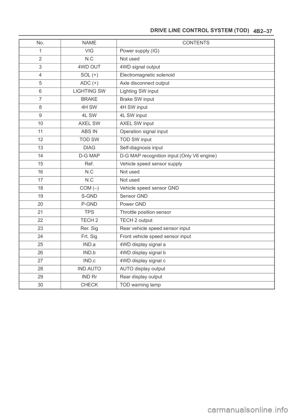
No.NAMECONTENTS
1VIGPower supply (IG)
2N.CNot used
34WD OUT4WD signal output
4SOL (+)Electromagnetic solenoid
5ADC (+)Axle disconnect output
6LIGHTING SWLighting SW input
7BRAKEBrake SW input
84H SW4H SW input
94L SW4L SW input
10AXEL SWAXEL SW input
11ABS INOperation signal input
12TOD SWTOD SW input
13DIAGSelf-diagnosis input
14D-G MAPD-G MAP recognition input (Only V6 engine)
15Ref.Vehicle speed sensor supply
16N.CNot used
17N.CNot used
18COM (–)Vehicle speed sensor GND
19S-GNDSensor GND
20P-GNDPower GND
21TPSThrottle position sensor
22TECH 2TECH 2 output
23Rer. SigRear vehicle speed sensor input
24Frt. SigFront vehicle speed sensor input
25IND.a4WD display signal a
26IND.b4WD display signal b
27IND.c4WD display signal c
28IND.AUTOAUTO display output
29IND RrRear display output
30CHECKTOD warning lamp
Page 4351 of 6000
5A–1 BRAKE CONTROL SYSTEM
BRAKES
CONTENTS
Brake Control System 5A. . . . . . . . . . . . . . . . . . . .
Anti–lock Brake System 5B. . . . . . . . . . . . . . . . . . Power–Assisted Brake System 5C. . . . . . . . . . . .
Parking Brakes 5D. . . . . . . . . . . . . . . . . . . . . . . . .
BRAKE CONTROL SYSTEM
CONTENTS
Service Precaution 5A–2. . . . . . . . . . . . . . . . . . . . . .
General Description 5A–3. . . . . . . . . . . . . . . . . . . . .
System Components 5A–3. . . . . . . . . . . . . . . . . . .
Electronic Hydraulic Control Unit (EHCU) 5A–3.
ABS Warning Light 5A–4. . . . . . . . . . . . . . . . . . . .
Wheel Speed Sensor 5A–4. . . . . . . . . . . . . . . . . .
G-Sensor 5A–4. . . . . . . . . . . . . . . . . . . . . . . . . . . . .
Normal and Anti-lock Braking 5A–4. . . . . . . . . . .
Brake Pedal Travel 5A–4. . . . . . . . . . . . . . . . . . . .
Acronyms and Abbreviations 5A–4. . . . . . . . . . . .
General Diagnosis 5A–5. . . . . . . . . . . . . . . . . . . . . . .
General Information 5A–5. . . . . . . . . . . . . . . . . . . .
ABS Service Precautions 5A–5. . . . . . . . . . . . . . .
Computer System Service Precautions 5A–5. . .
General Service Precautions 5A–5. . . . . . . . . . . .
Note on Intermittents 5A–5. . . . . . . . . . . . . . . . . . .
Test Driving ABS Complaint Vehicles 5A–6. . . . .
“ABS” Warning Light 5A–6. . . . . . . . . . . . . . . . . . .
Normal Operation 5A–6. . . . . . . . . . . . . . . . . . . . .
Basic Diagnostic Flow Chart 5A–6. . . . . . . . . . . .
Basic Inspection Procedure 5A–7. . . . . . . . . . . . .
Tech 2 Scan Tool 5A–8. . . . . . . . . . . . . . . . . . . . . .
Getting Started 5A–9. . . . . . . . . . . . . . . . . . . . . . . .
Operating Procedure 5A–10. . . . . . . . . . . . . . . . . . .
Data List 5A–11. . . . . . . . . . . . . . . . . . . . . . . . . . . . .
EHCU Connector Pin-out Checks 5A–12. . . . . . . .
Circuit Diagram (LHD model / 6VD1 and
4JG2) 5A–13. . . . . . . . . . . . . . . . . . . . . . . . . . . . . . .
Circuit Diagram (LHD model / 4JG2) 5A–14. . . . .
Circuit Diagram (LHD model / 4JG2) 5A–15. . . . .
Circuit Diagram (LHD model / 6VD1) 5A–16. . . . .
Circuit Diagram (LHD model / 6VD1) 5A–17. . . . .
Connector List (LHD model) 5A–18. . . . . . . . . . . .
Part Location (LHD model) 5A–20. . . . . . . . . . . . . .
Circuit Diagram (RHD model / 6VD1 and
4JG2) 5A–21. . . . . . . . . . . . . . . . . . . . . . . . . . . . . . .
Circuit Diagram (RHD model / 4JG2) 5A–22. . . . .
Circuit Diagram (RHD model / 4JG2) 5A–23. . . . .
Circuit Diagram (RHD model / 6VD1) 5A–24. . . . .
Circuit Diagram (RHD model / 6VD1) 5A–25. . . . .
Circuit Diagram (RHD model / 6VE1 and
4JX1) 5A–26. . . . . . . . . . . . . . . . . . . . . . . . . . . . . . . . Circuit Diagram (RHD model / 4JX1) 5A–27. . . . .
Circuit Diagram (RHD model / 4JX1) 5A–28. . . . .
Circuit Diagram (RHD model / 6VE1) 5A–29. . . . .
Circuit Diagram (RHD model / 6VE1) 5A–30. . . . .
Connector List (RHD model) 5A–31. . . . . . . . . . . .
Part Location (RHD model) 5A–34. . . . . . . . . . . . .
Symptom Diagnosis 5A–35. . . . . . . . . . . . . . . . . . . . .
Chart A–1 ABS Works Frequently But
Vehicle Does Not Decelerate 5A–35. . . . . . . . . . .
Chart TA-1 ABS Works Frequently But
Vehicle Does Not Decelerate (Use
TECH 2) 5A–36. . . . . . . . . . . . . . . . . . . . . . . . . . . . .
Chart A-2 Uneven Braking Occurs While
ABS Works 5A–36. . . . . . . . . . . . . . . . . . . . . . . . . . .
Chart A-3, TA-3 The Wheels Are Locked 5A–36.
Chart A-4 Brake Pedal Feed Is Abnormal 5A–37.
Chart A-5, TA-5 Braking Sound (From
EHCU) Is Heard While Not Braking 5A–38. . . . . .
Diagnostic Trouble Codes 5A–39. . . . . . . . . . . . . . . .
Diagnosis By “ABS” Warning Light
Illumination Pattern 5A–40. . . . . . . . . . . . . . . . . . . . .
Diagnostic Trouble Codes (DTCs) 5A–40. . . . . . .
Chart B-1 With the key in the ON position
(Before starting the engine). Warning light
(W/L) is not activated. 5A–43. . . . . . . . . . . . . . . . .
Chart B-2 EHCU Abnormality (DTC 14) 5A–43. . .
Chart B-3 Power Voltage Drop (DTC 15) 5A–44. .
Chart B-4 CLASS-2 Communication Line
Abnormality (DTC 16) 5A–44. . . . . . . . . . . . . . . . .
Chart B-5 G-Sensor Circuit (DTC 21) 5A–45. . . . .
Chart B-6 Abnormal Transmission Input
(DTC 23) 5A–46. . . . . . . . . . . . . . . . . . . . . . . . . . . .
Chart B-7 Transfer Monitor (DTC 24) 5A–47. . . . .
Chart B-8 EHCU Pump Motor And Motor
Relay Circuit (DTC 32) 5A–47. . . . . . . . . . . . . . . . .
Chart B-9 EHCU Pump Valve And Valve
Relay Circuit (DTC 35) 5A–47. . . . . . . . . . . . . . . . .
Chart B-10 FL Isolation Solenoid Valve
Abnormality (DTC 41) 5A–48. . . . . . . . . . . . . . . . .
Chart B-11 FL Dump Solenoid Valve
Abnormality (DTC 42) 5A–48. . . . . . . . . . . . . . . . .
Chart B-12 FR Isolation Solenoid Valve
Abnormality (DTC 43) 5A–48. . . . . . . . . . . . . . . . .
Chart B-13 FR Dump Solenoid Valve
Abnormality (DTC 44) 5A–49. . . . . . . . . . . . . . . . .
Chart B-14 Rear Isolation Solenoid Valve
Abnormality (DTC 45) 5A–49. . . . . . . . . . . . . . . . .
Chart B-15 Rear Dump Solenoid Valve
Abnormality (DTC 46) 5A–49. . . . . . . . . . . . . . . . .