1998 OPEL FRONTERA battery
[x] Cancel search: batteryPage 993 of 6000

6A–37
ENGINE MECHANICAL
Cylinder Head
Removal
1. Remove engine hood.
2. Disconnect battery ground cable.
3. Drain radiator coolant.
4. Drain engine oil.
5. Remove crankshaft pulley.
Refer to removal procedure for Crankshaft Pulley in
this manual.
6. Remove timing belt.
Refer to removal procedure for Timing Belt in this
manual.
7. Remove cylinder head cover LH.
Refer to removal procedure for Cylinder Head
Cover LH in this manual.
8. Remove cylinder head cover RH.
Refer to removal procedure for Cylinder Head
Cover RH in this manual.
9. Remove common chamber.
Refer to removal procedure for Common Chamber
in this manual.
10. Remove cylinder head assembly.
1. Loosen eights bolts for tight cylinder head.
2. Remove cylinder head assembly.
014RW028
Legend
(1) Cylinder Head
(2) Cylinder Head Bolt
(3) Camshaft
Installation
1. Install cylinder head assembly to cylinder block.
1. Put cylinder head gasket on the cylinder block.NOTE: There is discrimination mark “R” for right bank
and “L” for left bank on the cylinder head gasket as shown
in the illustration.
Do not reuse cylinder head gasket.
011RW005
2. Align dowel pin hole to dowel pin on the cylinder
block.
3. Tighten two bolts temporarily by hand to prevent
the cylinder head assembly from moving.
4. Using 9–8511–4209–0 cylinder head bolt wrench,
tighten bolts in numerical order as shown in the
illustration to the specified torque.
NOTE: Do not reuse cylinder head bolts.
Do not apply any lubricant to the cylinder head bolts.
To r q u e :
Temporary : 29 Nꞏm (3.0 Kgꞏm/21 lb ft)
Final : 64 Nꞏm (6.5 Kgꞏm/47 lb ft)
014RW029
Page 995 of 6000

6A–39
ENGINE MECHANICAL
Valve Stem Oil Controller , Valve Spring and Valve Guide
Removal
1. Disconnect battery ground cable.
2. Drain engine oil.
Drain engine coolant.
3. Remove cylinder head assembly.
Refer to removal procedure for Cylinder Head in
this manual.
4. Remove camshaft.
Refer to removal procedure for Camshaft in this
manual.
5. Remove tappets with shim.
NOTE: Do not damage shim surface.
6. Remove valve springs using 5–8840–2446–0 valve
spring compressor and 5–8840–2547–0 valve spring
compressor adapter then remove upper valve spring
seat and lower seat.
014RW042
7. Remove oil controller using 5–8840–0623–0 oil
controller remover, remove each valve stem oil
controller.
8. Remove valve guide using 5–8840–2549–0 valve
guide replacer.
Installation
1. Install valve guide using 5–8840–2442–0 valve guide
installer.
2. Install oil controller using 5–8840–0624–0 oil
controller installer.
3. Install lower valve spring seat, valve spring and upper
valve spring seat then put split collars on the upper
spring seat, using 5–8840–2446–0 valve spring
compressor and 5–8840–2547–0 valve spring
compressor adapter to install the split collars.
014RW042
4. Install tappet with shim.
5. Install camshaft assembly.
Refer to installation procedure for Camshaft in this
manual.
6. Install cylinder head assembly.
Refer to installation procedure for Cylinder Head in
this manual.
7. Fill engine oil until full level.
8. Fill engine coolant.
Page 1004 of 6000
6A–48
ENGINE MECHANICAL
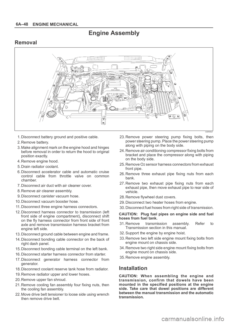
Engine Assembly
Removal
035RW027
1. Disconnect battery ground and positive cable.
2. Remove battery.
3. Make alignment mark on the engine hood and hinges
before removal in order to return the hood to original
position exactly.
4. Remove engine hood.
5. Drain radiator coolant.
6. Disconnect accelerator cable and automatic cruise
control cable from throttle valve on common
chamber.
7. Disconnect air duct with air cleaner cover.
8. Remove air cleaner assembly.
9. Disconnect canister vacuum hose.
10. Disconnect vacuum booster hose.
11. Disconnect three engine harness connectors.
12. Disconnect harness connector to transmission (left
front side of engine compartment), disconnect shift
on the fly harness connector from front side of front
axle and remove transmission harness bracket from
engine left side.
13. Disconnect ground cable between engine and frame.
14. Disconnect bonding cable connector on the back of
right dash panel.
15. Disconnect bonding cable terminal on the left bank.
16. Disconnect starter harness connector from starter.
17. Disconnect generator harness connector from
generator.
18. Disconnect coolant reserve tank hose from radiator.
19. Remove radiator upper and lower hoses.
20. Remove upper fan shroud.
21. Remove cooling fan assembly four fixing nuts, then
the cooling fan assembly.
22. Move drive belt tensioner to loose side using wrench
then remove drive belt.23. Remove power steering pump fixing bolts, then
power steering pump. Place the power steering pump
along with piping on the body side.
24. Remove air conditioning compressor fixing bolts from
bracket and place the compressor along with piping
on the body side.
25. Remove O
2 sensor harness connectors from exhaust
front pipe.
26. Remove three exhaust pipe fixing nuts from each
bank.
27. Remove two exhaust pipe fixing nuts from each
exhaust pipe, then move exhaust pipe to rear side of
vehicle.
28. Remove flywheel dust covers.
29. Disconnect two heater hoses from engine.
30. Disconnect fuel hoses from right side of transmission.
CAUTION: Plug fuel pipes on engine side and fuel
hoses from fuel tank.
31. Remove transmission assembly. Refer to
Transmission section in this manual.
32. Support the engine by engine hoist.
33. Remove two left side engine mount fixing bolts from
engine mount on chassis side.
34. Remove two right side engine mount fixing bolts from
engine mount on chassis side.
35. Remove engine assembly.
Installation
CAUTION: W h e n a s s e m b l i n g t h e e n g i n e a n d
transmission, confirm that dowels have been
mounted in the specified positions at the engine
side. Take care that dowel positions are different
between the manual transmission and the automatic
transmission.
Page 1060 of 6000
ENGINE COOLING6B–7
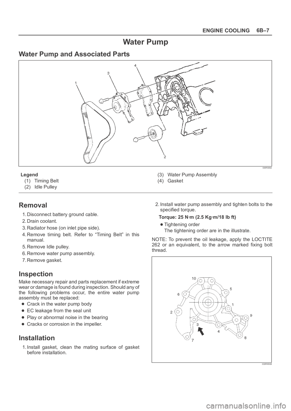
Water Pump
Water Pump and Associated Parts
030RS002
Legend
(1) Timing Belt
(2) Idle Pulley(3) Water Pump Assembly
(4) Gasket
Removal
1. Disconnect battery ground cable.
2. Drain coolant.
3. Radiator hose (on inlet pipe side).
4. Remove timing belt. Refer to “Timing Belt” in this
manual.
5. Remove Idle pulley.
6. Remove water pump assembly.
7. Remove gasket.
Inspection
Make necessary repair and parts replacement if extreme
wear or damage is found during inspection. Should any of
the following problems occur, the entire water pump
assembly must be replaced:
Crack in the water pump body
EC leakage from the seal unit
Play or abnormal noise in the bearing
Cracks or corrosion in the impeller.
Installation
1. Install gasket, clean the mating surface of gasket
before installation.2. Install water pump assembly and tighten bolts to the
specified torque.
Torque: 25 Nꞏm (2.5 Kgꞏm/18 lb ft)
Tightening order
The tightening order are in the illustrate.
NOTE: To prevent the oil leakage, apply the LOCTITE
262 or an equivalent, to the arrow marked fixing bolt
thread.
030RW008
Page 1061 of 6000
6B–8
ENGINE COOLING
3. Idle pulley
Install idle pulley and tighten bolt to the specified
torque.
Torque: 52 Nꞏm (5.3 Kgꞏm/38 lb ft)4. Timing beltInstall timing belt. Refer to timing belt installation
step in “Timing Belt” in this manual.
5. Connect radiator inlet hose and replenish EC.
6. Connect battery ground cable.
Thermostat
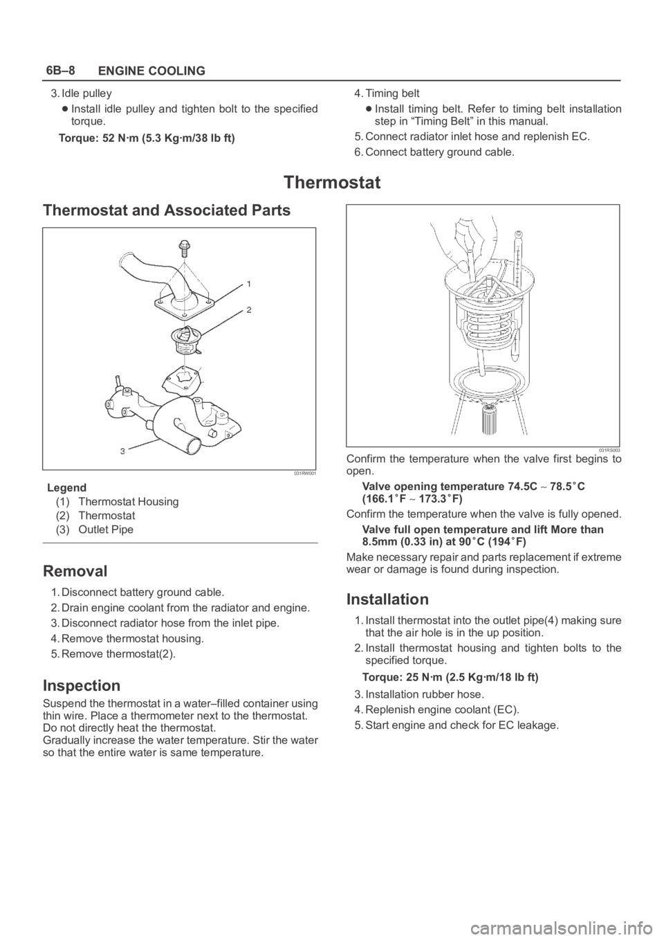
Thermostat and Associated Parts
031RW001
Legend
(1) Thermostat Housing
(2) Thermostat
(3) Outlet Pipe
Removal
1. Disconnect battery ground cable.
2. Drain engine coolant from the radiator and engine.
3. Disconnect radiator hose from the inlet pipe.
4. Remove thermostat housing.
5. Remove thermostat(2).
Inspection
Suspend the thermostat in a water–filled container using
thin wire. Place a thermometer next to the thermostat.
Do not directly heat the thermostat.
Gradually increase the water temperature. Stir the water
so that the entire water is same temperature.
031RS003Confirm the temperature when the valve first begins to
open.
Valve opening temperature 74.5C
78.5C
(166.1
F 173.3F)
Confirm the temperature when the valve is fully opened.
Valve full open temperature and lift More than
8.5mm (0.33 in) at 90
C (194F)
Make necessary repair and parts replacement if extreme
wear or damage is found during inspection.
Installation
1. Install thermostat into the outlet pipe(4) making sure
that the air hole is in the up position.
2. Install thermostat housing and tighten bolts to the
specified torque.
Torque: 25 Nꞏm (2.5 Kgꞏm/18 lb ft)
3. Installation rubber hose.
4. Replenish engine coolant (EC).
5. Start engine and check for EC leakage.
Page 1062 of 6000
ENGINE COOLING6B–9
Radiator
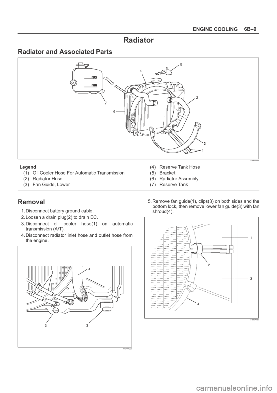
Radiator and Associated Parts
110RW003
Legend
(1) Oil Cooler Hose For Automatic Transmission
(2) Radiator Hose
(3) Fan Guide, Lower(4) Reserve Tank Hose
(5) Bracket
(6) Radiator Assembly
(7) Reserve Tank
Removal
1. Disconnect battery ground cable.
2. Loosen a drain plug(2) to drain EC.
3. Disconnect oil cooler hose(1) on automatic
transmission (A/T).
4. Disconnect radiator inlet hose and outlet hose from
the engine.
110RW002
5. Remove fan guide(1), clips(3) on both sides and the
bottom lock, then remove lower fan guide(3) with fan
shroud(4).
110RW001
Page 1064 of 6000
ENGINE COOLING6B–11
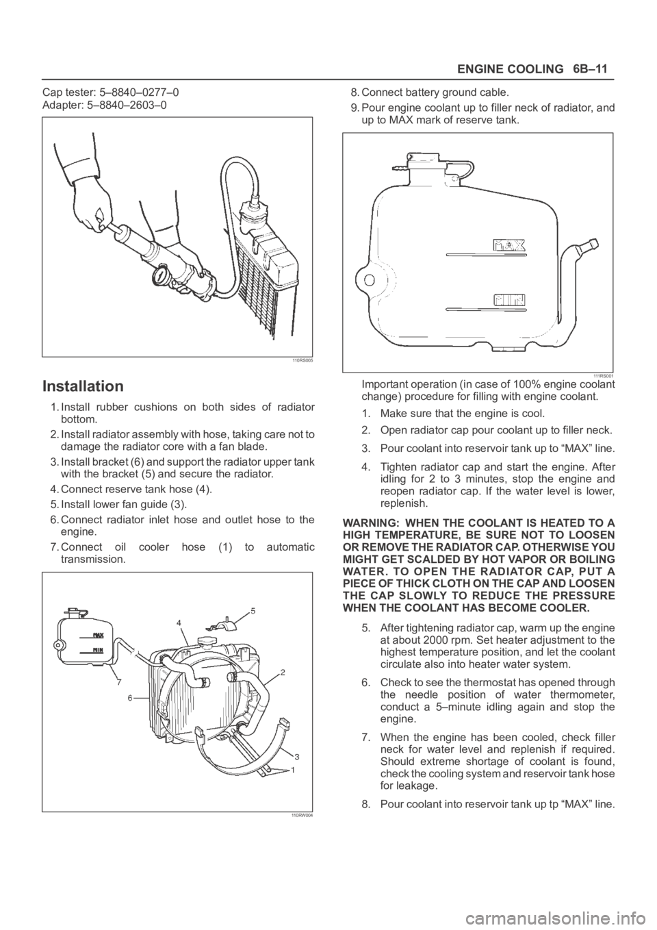
Cap tester: 5–8840–0277–0
Adapter: 5–8840–2603–0
110RS005
Installation
1. Install rubber cushions on both sides of radiator
bottom.
2. Install radiator assembly with hose, taking care not to
damage the radiator core with a fan blade.
3. Install bracket (6) and support the radiator upper tank
with the bracket (5) and secure the radiator.
4. Connect reserve tank hose (4).
5. Install lower fan guide (3).
6. Connect radiator inlet hose and outlet hose to the
engine.
7. Connect oil cooler hose (1) to automatic
transmission.
110RW004
8. Connect battery ground cable.
9. Pour engine coolant up to filler neck of radiator, and
up to MAX mark of reserve tank.
111 R S 0 0 1Important operation (in case of 100% engine coolant
change) procedure for filling with engine coolant.
1. Make sure that the engine is cool.
2. Open radiator cap pour coolant up to filler neck.
3. Pour coolant into reservoir tank up to “MAX” line.
4. Tighten radiator cap and start the engine. After
idling for 2 to 3 minutes, stop the engine and
reopen radiator cap. If the water level is lower,
replenish.
WARNING: WHEN THE COOLANT IS HEATED TO A
HIGH TEMPERATURE, BE SURE NOT TO LOOSEN
OR REMOVE THE RADIATOR CAP. OTHERWISE YOU
MIGHT GET SCALDED BY HOT VAPOR OR BOILING
WATER. TO OPEN THE RADIATOR CAP, PUT A
PIECE OF THICK CLOTH ON THE CAP AND LOOSEN
THE CAP SLOWLY TO REDUCE THE PRESSURE
WHEN THE COOLANT HAS BECOME COOLER.
5. After tightening radiator cap, warm up the engine
at about 2000 rpm. Set heater adjustment to the
highest temperature position, and let the coolant
circulate also into heater water system.
6. Check to see the thermostat has opened through
the needle position of water thermometer,
conduct a 5–minute idling again and stop the
engine.
7. When the engine has been cooled, check filler
neck for water level and replenish if required.
Should extreme shortage of coolant is found,
check the cooling system and reservoir tank hose
for leakage.
8. Pour coolant into reservoir tank up tp “MAX” line.
Page 1069 of 6000
6C–2
ENGINE FUEL
General Description
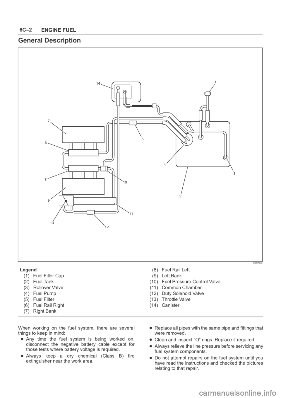
140RW030
Legend
(1) Fuel Filler Cap
(2) Fuel Tank
(3) Rollover Valve
(4) Fuel Pump
(5) Fuel Filter
(6) Fuel Rail Right
(7) Right Bank(8) Fuel Rail Left
(9) Left Bank
(10) Fuel Pressure Control Valve
(11) Common Chamber
(12) Duty Solenoid Valve
(13) Throttle Valve
(14) Canister
When working on the fuel system, there are several
things to keep in mind:
Any time the fuel system is being worked on,
disconnect the negative battery cable except for
those tests where battery voltage is required.
Always keep a dry chemical (Class B) fire
extinguisher near the work area.
Replace all pipes with the same pipe and fittings that
were removed.
Clean and inspect “O” rings. Replace if required.
Always relieve the line pressure before servicing any
fuel system components.
Do not attempt repairs on the fuel system until you
have read the instructions and checked the pictures
relating to that repair.