1998 OPEL FRONTERA engine oil
[x] Cancel search: engine oilPage 4617 of 6000
6C–10
ENGINE FUEL
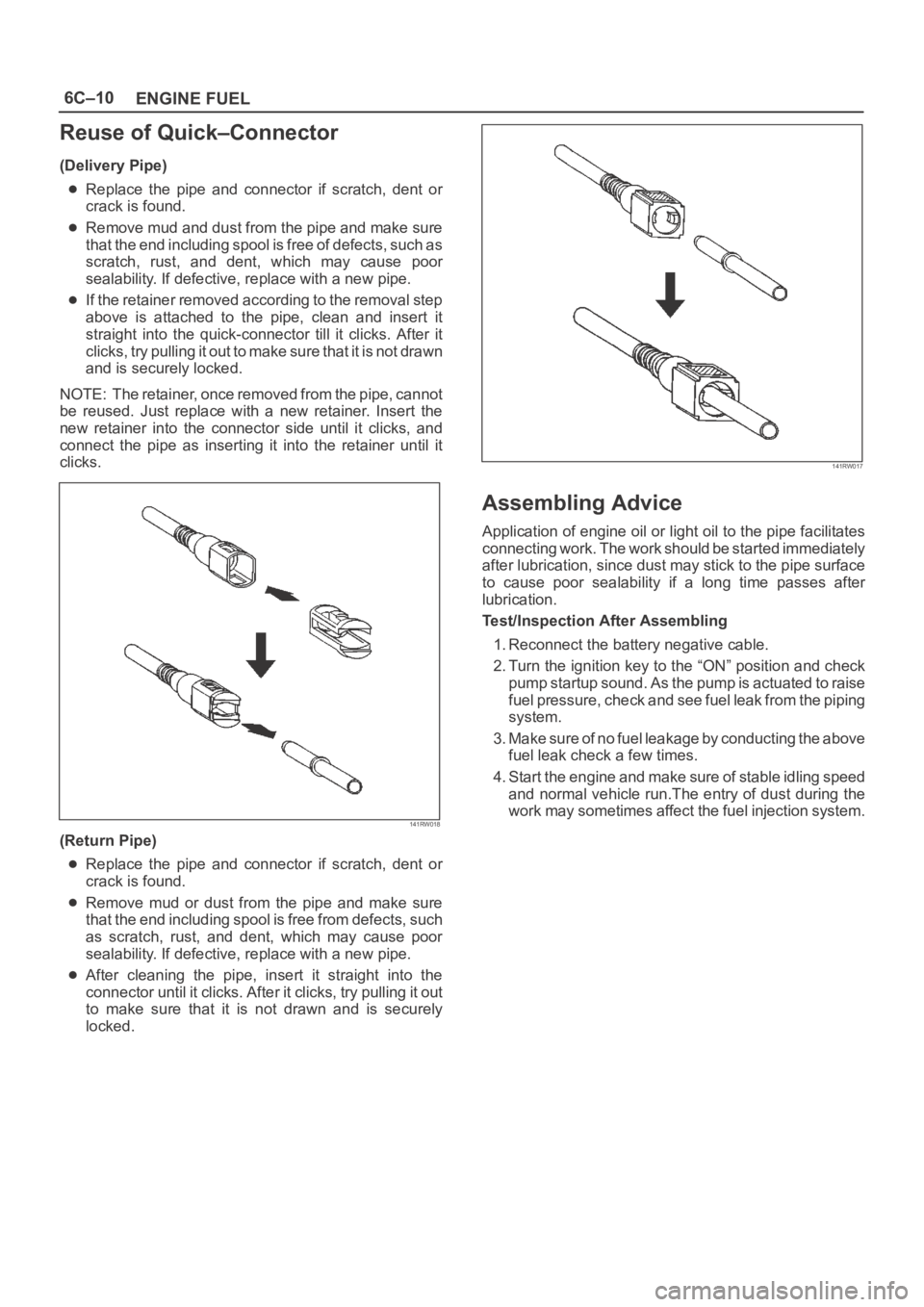
Reuse of Quick–Connector
(Delivery Pipe)
Replace the pipe and connector if scratch, dent or
crack is found.
Remove mud and dust from the pipe and make sure
that the end including spool is free of defects, such as
scratch, rust, and dent, which may cause poor
sealability. If defective, replace with a new pipe.
If the retainer removed according to the removal step
above is attached to the pipe, clean and insert it
straight into the quick-connector till it clicks. After it
clicks, try pulling it out to make sure that it is not drawn
and is securely locked.
NOTE: The retainer, once removed from the pipe, cannot
be reused. Just replace with a new retainer. Insert the
new retainer into the connector side until it clicks, and
connect the pipe as inserting it into the retainer until it
clicks.
141RW018
(Return Pipe)
Replace the pipe and connector if scratch, dent or
crack is found.
Remove mud or dust from the pipe and make sure
that the end including spool is free from defects, such
as scratch, rust, and dent, which may cause poor
sealability. If defective, replace with a new pipe.
After cleaning the pipe, insert it straight into the
connector until it clicks. After it clicks, try pulling it out
to make sure that it is not drawn and is securely
locked.
141RW017
Assembling Advice
Application of engine oil or light oil to the pipe facilitates
connecting work. The work should be started immediately
after lubrication, since dust may stick to the pipe surface
to cause poor sealability if a long time passes after
lubrication.
Test/Inspection After Assembling
1. Reconnect the battery negative cable.
2. Turn the ignition key to the “ON” position and check
pump startup sound. As the pump is actuated to raise
fuel pressure, check and see fuel leak from the piping
system.
3. Make sure of no fuel leakage by conducting the above
fuel leak check a few times.
4. Start the engine and make sure of stable idling speed
and normal vehicle run.The entry of dust during the
work may sometimes affect the fuel injection system.
Page 4626 of 6000
6D2–1
IGNITION SYSTEM
ENGINE
IGNITION SYSTEM
CONTENTS
Service Precaution 6D2–1. . . . . . . . . . . . . . . . . . . . . .
General Description 6D2–2. . . . . . . . . . . . . . . . . . . . .
Diagnosis 6D2–2. . . . . . . . . . . . . . . . . . . . . . . . . . . . . .
Ignition Coil 6D2–3. . . . . . . . . . . . . . . . . . . . . . . . . . . . .
Removal 6D2–3. . . . . . . . . . . . . . . . . . . . . . . . . . . . .
Inspection and Repair 6D2–3. . . . . . . . . . . . . . . . . .
Installation 6D2–3. . . . . . . . . . . . . . . . . . . . . . . . . . . .
Spark Plug 6D2–4. . . . . . . . . . . . . . . . . . . . . . . . . . . . . Removal 6D2–4. . . . . . . . . . . . . . . . . . . . . . . . . . . . .
Inspection and Repair 6D2–4. . . . . . . . . . . . . . . . . .
Installation 6D2–4. . . . . . . . . . . . . . . . . . . . . . . . . . . .
Crankshaft Angle Sensor 6D2–5. . . . . . . . . . . . . . . . .
Removal 6D2–5. . . . . . . . . . . . . . . . . . . . . . . . . . . . .
Installation 6D2–5. . . . . . . . . . . . . . . . . . . . . . . . . . . .
Main Data and Specifications 6D2–6. . . . . . . . . . . . .
Service Precaution
WARNING: IF SO EQUIPPED WITH A
SUPPLEMENTAL RESTRAINT SYSTEM (SRS),
REFER TO THE SRS COMPONENT AND WIRING
LOCATION VIEW IN ORDER TO DETERMINE
WHETHER YOU ARE PERFORMING SERVICE ON OR
NEAR THE SRS COMPONENTS OR THE SRS
WIRING. WHEN YOU ARE PERFORMING SERVICE
ON OR NEAR THE SRS COMPONENTS OR THE SRS
WIRING, REFER TO THE SRS SERVICE
INFORMATION. FAILURE TO FOLLOW WARNINGS
COULD RESULT IN POSSIBLE AIR BAG
DEPLOYMENT, PERSONAL INJURY, OR
OTHERWISE UNNEEDED SRS SYSTEM REPAIRS.
CAUTION: Always use the correct fastener in the
proper location. When you replace a fastener, use
ONLY the exact part number for that application.
ISUZU will call out those fasteners that require a
replacement after removal. ISUZU will also call out
the fasteners that require thread lockers or thread
sealant. UNLESS OTHERWISE SPECIFIED, do not
use supplemental coatings (Paints, greases, or other
corrosion inhibitors) on threaded fasteners or
fastener joint interfaces. Generally, such coatings
adversely affect the fastener torque and the joint
clamping force, and may damage the fastener. When
you install fasteners, use the correct tightening
sequence and specifications. Following these
instructions can help you avoid damage to parts and
systems.
Page 4627 of 6000
6D2–2
IGNITION SYSTEM
General Description
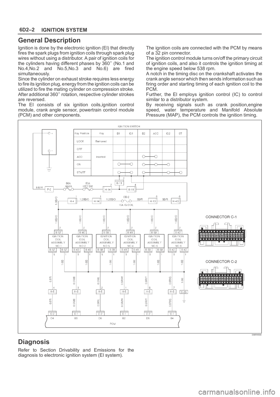
Ignition is done by the electronic ignition (El) that directly
fires the spark plugs from ignition coils through spark plug
wires without using a distributor. A pair of ignition coils for
the cylinders having different phases by 360
(No.1 and
No.4,No.2 and No.5,No.3 and No.6) are fired
simultaneously.
Since the cylinder on exhaust stroke requires less energy
to fire its ignition plug, energy from the ignition coils can be
utilized to fire the mating cylinder on compression stroke.
After additional 360
rotation, respective cylinder strokes
are reversed.
The EI consists of six ignition coils,ignition control
module, crank angle sensor, powertrain control module
(PCM) and other components.The ignition coils are connected with the PCM by means
of a 32 pin connector.
The ignition control module turns on/off the primary circuit
of ignition coils, and also it controls the ignition timing at
the engine speed below 538 rpm.
A notch in the timing disc on the crankshaft activates the
crank angle sensor which then sends information such as
firing order and starting timing of each ignition coil to the
PCM.
Further, the El employs ignition control (IC) to control
similar to a distributor system.
By receiving signals such as crank position,engine
speed, water temperature and Manifold Absolute
Pressure (MAP), the PCM controls the ignition timing.
D06RW084
Diagnosis
Refer to Section Drivability and Emissions for the
diagnosis to electronic ignition system (El system).
Page 4629 of 6000
6D2–4
IGNITION SYSTEM
Spark Plug
Removal
1. Remove spark plugs.
Inspection and Repair
The spark plug affects entire engine performance and
therefore its inspection is very important.
Check electrode and insulator for presence of cracks,
and replace if any.
Check electrode for wear, and replace if necessary.
Check gasket for damage, and replace if necessary.
Measure insulation resistance with an ohmmeter, and
replace if faulty.
Adjust spark plug gap to 1.0 mm (0.04 in) 1.1 mm
(0.043 in).
Check fuel and electrical systems if spark plug is
extremely dirty.
Use spark plugs having low heat value (hot type plug)
if fuel and electrical systems are normal.
Use spark plugs having high heat value (cold type
plug) if insulator and electrode are extremely burned.
Sooty Spark Plugs
Much deposit of carbon or oil on the electrode and
insulator of spark plug reduces the engine performance.
Possible causes:
Too rich mixture
Presence of oil in combustion chamber
Incorrectly adjusted spark plug gap
Burning Electrodes
This fault is characterized by scorched or heavily oxidized
electrode or blistered insulator nose.
Possible causes:
Too lean mixture
Improper heat value
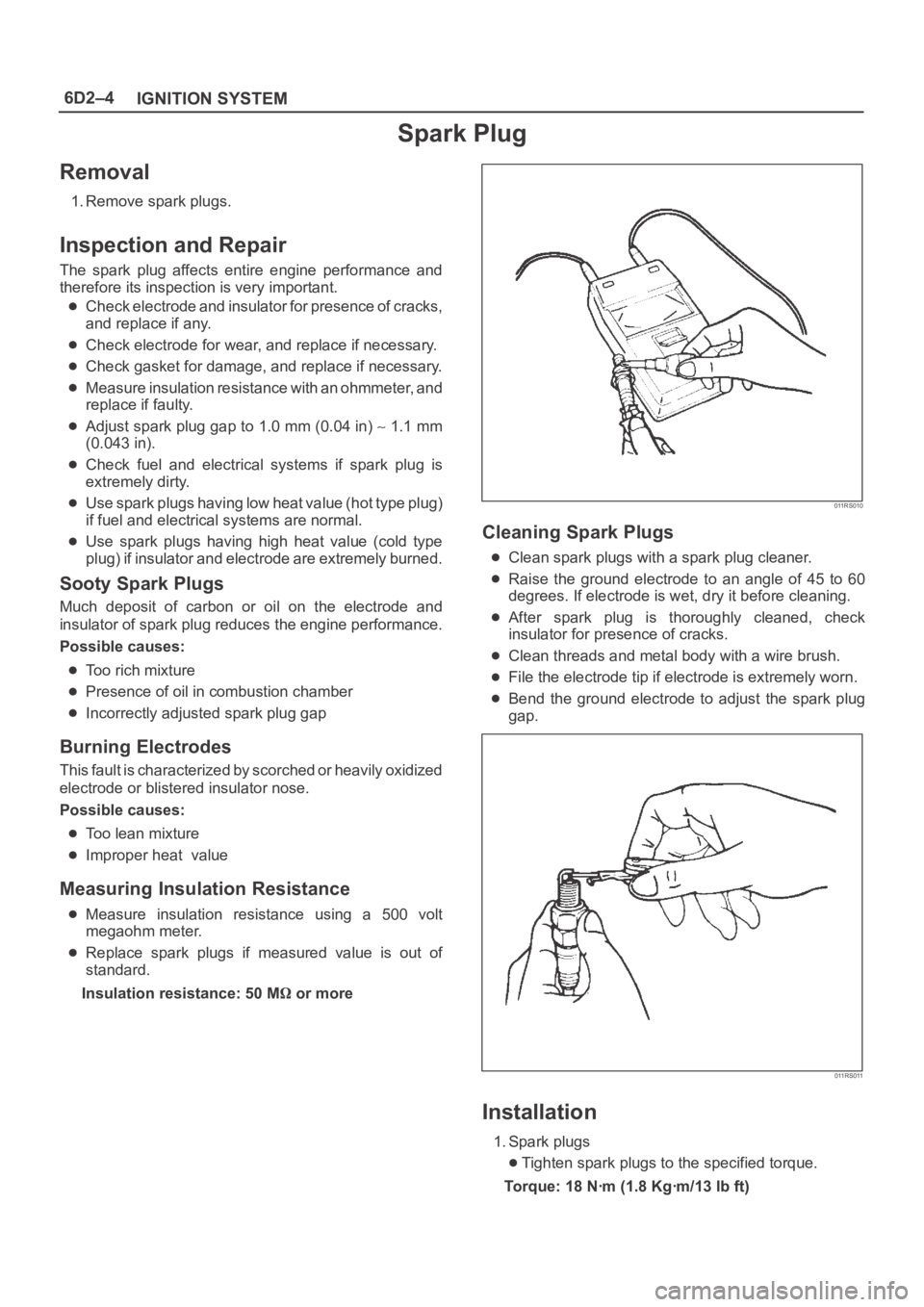
Measuring Insulation Resistance
Measure insulation resistance using a 500 volt
megaohm meter.
Replace spark plugs if measured value is out of
standard.
Insulation resistance: 50 M
or more
011RS010
Cleaning Spark Plugs
Clean spark plugs with a spark plug cleaner.
Raise the ground electrode to an angle of 45 to 60
degrees. If electrode is wet, dry it before cleaning.
After spark plug is thoroughly cleaned, check
insulator for presence of cracks.
Clean threads and metal body with a wire brush.
File the electrode tip if electrode is extremely worn.
Bend the ground electrode to adjust the spark plug
gap.
011RS011
Installation
1. Spark plugs
Tighten spark plugs to the specified torque.
Torque: 18 Nꞏm (1.8 Kgꞏm/13 lb ft)
Page 4630 of 6000
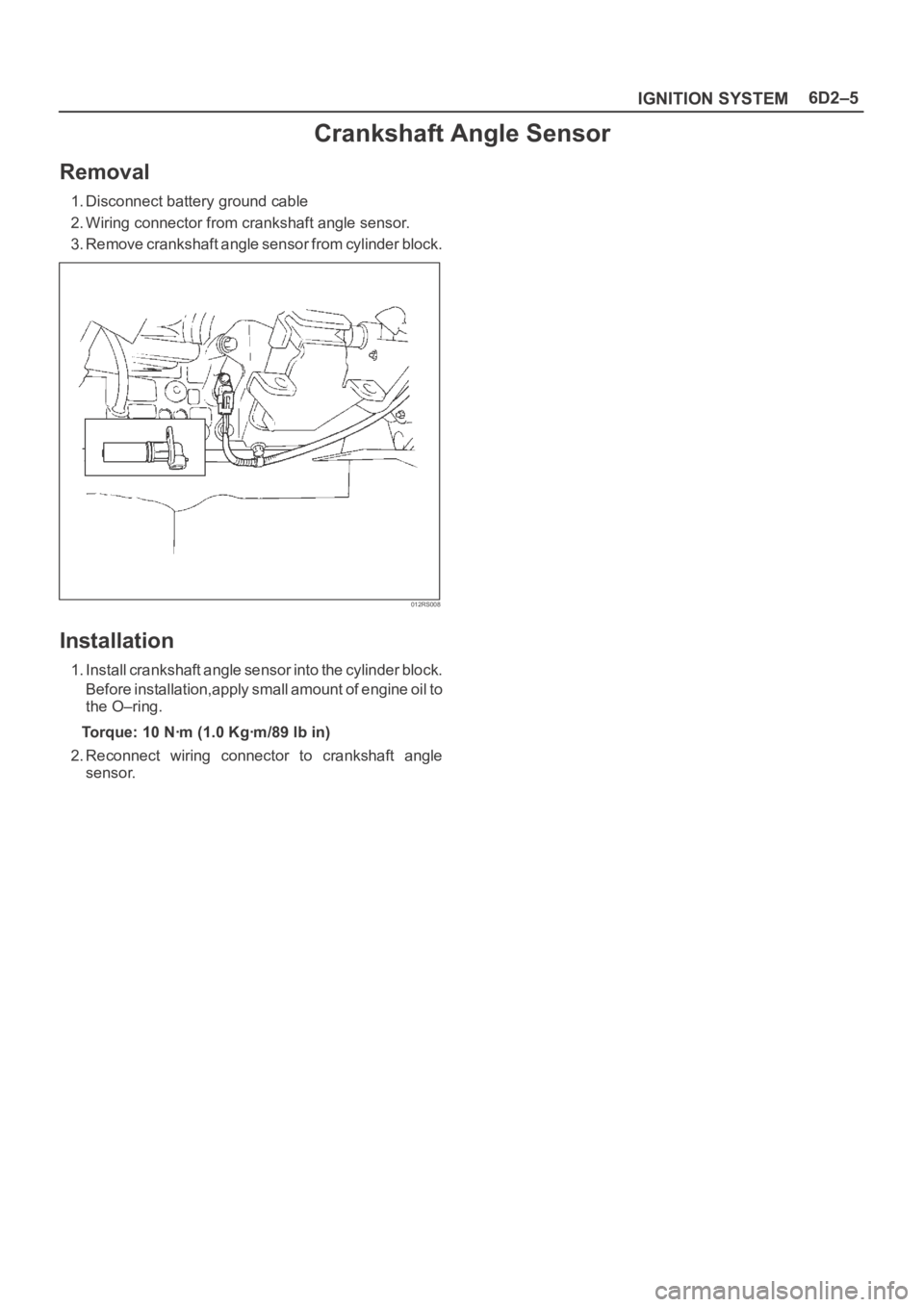
6D2–5
IGNITION SYSTEM
Crankshaft Angle Sensor
Removal
1. Disconnect battery ground cable
2. Wiring connector from crankshaft angle sensor.
3. Remove crankshaft angle sensor from cylinder block.
012RS008
Installation
1. Install crankshaft angle sensor into the cylinder block.
Before installation,apply small amount of engine oil to
the O–ring.
Torque: 10 Nꞏm (1.0 Kgꞏm/89 lb in)
2. Reconnect wiring connector to crankshaft angle
sensor.
Page 4649 of 6000
6D3–18STARTING AND CHARGING SYSTEM
Charging System
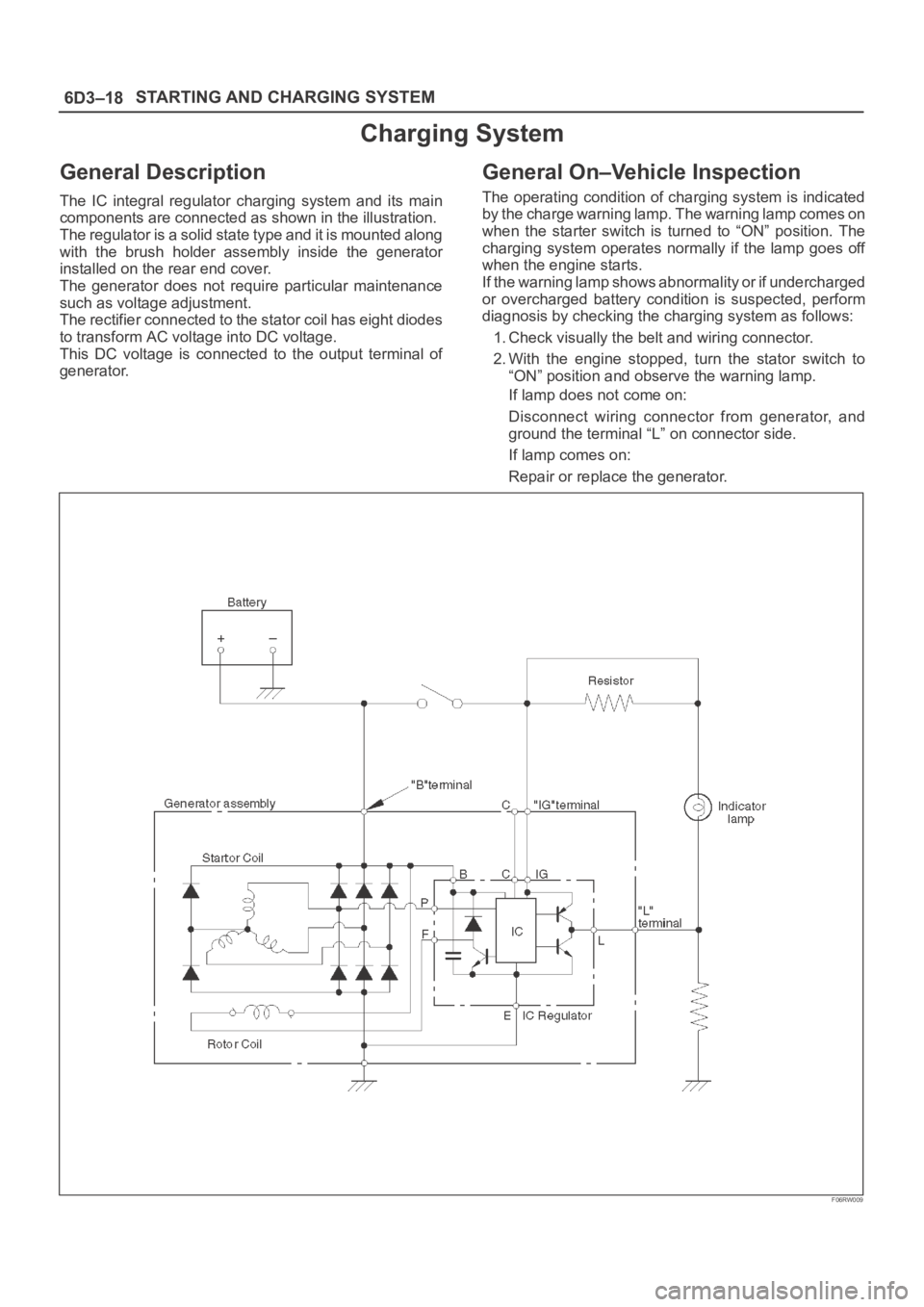
General Description
The IC integral regulator charging system and its main
components are connected as shown in the illustration.
The regulator is a solid state type and it is mounted along
with the brush holder assembly inside the generator
installed on the rear end cover.
The generator does not require particular maintenance
such as voltage adjustment.
The rectifier connected to the stator coil has eight diodes
to transform AC voltage into DC voltage.
This DC voltage is connected to the output terminal of
generator.
General On–Vehicle Inspection
The operating condition of charging system is indicated
by the charge warning lamp. The warning lamp comes on
when the starter switch is turned to “ON” position. The
charging system operates normally if the lamp goes off
when the engine starts.
If the warning lamp shows abnormality or if undercharged
or overcharged battery condition is suspected, perform
diagnosis by checking the charging system as follows:
1. Check visually the belt and wiring connector.
2. With the engine stopped, turn the stator switch to
“ON” position and observe the warning lamp.
If lamp does not come on:
Disconnect wiring connector from generator, and
ground the terminal “L” on connector side.
If lamp comes on:
Repair or replace the generator.
F06RW009
Page 4659 of 6000
6E–2
ENGINE DRIVEABILITY AND EMISSIONS
Primary System-Based Diagnostic 6E–50. . . . . . . . .
Primary System-Based Diagnostic 6E–50. . . . . . .
Fuel Control Heated Oxygen Sensor 6E–50. . . . .
HO2S Heater 6E–50. . . . . . . . . . . . . . . . . . . . . . . . .
Fuel Trim System Monitor Diagnostic
Operation 6E–50. . . . . . . . . . . . . . . . . . . . . . . . . . . . . .
Fuel Trim System Monitor Diagnostic
Operation 6E–50. . . . . . . . . . . . . . . . . . . . . . . . . . . .
Fuel Trim Cell Diagnostic Weights 6E–50. . . . . . .
On-Board Diagnostic (OBD) System Check 6E–51.
A/C Clutch Control Circuit Diagnosis 6E–54. . . . . . .
Electronic Ignition System Diagnosis 6E–60. . . . . . .
Fuel Metering System Check 6E–60. . . . . . . . . . . . .
Idle Air Control (IAC) Valve 6E–60. . . . . . . . . . . . . . .
Fuel System Pressure Test 6E–60. . . . . . . . . . . . . . .
Fuel Injector Coil Test Procedure and Fuel
Injector Balance Test Procedure 6E–60. . . . . . . . . .
Knock Sensor Diagnosis 6E–65. . . . . . . . . . . . . . . . .
Powertrain Control Module (PCM) Diagnosis 6E–65
Multiple PCM Information Sensor DTCS Set 6E–65
Exhaust Gas Recirculation (EGR) Diagnosis
(For except EXPORT and
SOUTH AFRICA) 6E–68. . . . . . . . . . . . . . . . . . . . . . .
Engine Tech 2 Data Definitions and Ranges 6E–68
Typical Scan Data Values 6E–70. . . . . . . . . . . . . . . .
No Malfunction Indicator Lamp (MIL) 6E–74. . . . . . .
Malfunction Indicator Lamp (MIL) “ON”
Steady 6E–77. . . . . . . . . . . . . . . . . . . . . . . . . . . . . . . .
Engine Cranks But Will Not Run 6E–79. . . . . . . . . . .
Fuel System Electrical Test 6E–85. . . . . . . . . . . . . . .
Fuel System Diagnosis 6E–88. . . . . . . . . . . . . . . . . . .
Idle Air Control (IAC) System Check 6E–93. . . . . . .
Knock Sensor (KS) System Check
(Engine Knock, Poor Performance, or Poor
Economy) 6E–95. . . . . . . . . . . . . . . . . . . . . . . . . . . . .
Exhaust Gas Recirculation (EGR) System
Check 6E–97. . . . . . . . . . . . . . . . . . . . . . . . . . . . . . . . .
Manifold Absolute Pressure (MAP) Output
Check 6E–99. . . . . . . . . . . . . . . . . . . . . . . . . . . . . . . . .
PCM Diagnostic Trouble Codes 6E–101. . . . . . . . . . .
Diagnostic Trouble Code (DTC) P0101
MAF System Performance 6E–104. . . . . . . . . . . . . . .
Diagnostic Trouble Code (DTC) P0102
MAF Sensor Circuit Low Frequency 6E–107. . . . . .
Diagnostic Trouble Code (DTC) P0103
MAF Sensor Circuit High Frequency 6E–110. . . . . .
Diagnostic Trouble Code (DTC) P0107
MAP Sensor Circuit Low Voltage 6E–112. . . . . . . . . .
Diagnostic Trouble Code (DTC) P0108
MAP Sensor Circuit High Voltage 6E–115. . . . . . . . .
Diagnostic Trouble Code (DTC) P0112
IAT Sensor Circuit Low Voltage 6E–118. . . . . . . . . . .
Diagnostic Trouble Code (DTC) P0113
IAT Sensor Circuit High Voltage 6E–121. . . . . . . . . . Diagnostic Trouble Code (DTC) P0117
ECT Sensor Circuit Low Voltage 6E–124. . . . . . . . . .
Diagnostic Trouble Code (DTC) P0118
ECT Sensor Circuit High Voltage 6E–127. . . . . . . . .
Diagnostic Trouble Code (DTC) P0121
TP System Performance 6E–130. . . . . . . . . . . . . . . . .
Diagnostic Trouble Code (DTC) P0122
TP Sensor Circuit Low Voltage 6E–133. . . . . . . . . . .
Diagnostic Trouble Code (DTC) P0123
TP Sensor Circuit High Voltage 6E–136. . . . . . . . . .
Diagnostic Trouble Code (DTC) P0131
HO2S Circuit Low Voltage Bank 1
Sensor 1 6E–139. . . . . . . . . . . . . . . . . . . . . . . . . . . . . . .
Diagnostic Trouble Code (DTC) P0132
HO2S Circuit High Voltage Bank 1
Sensor 1 6E–142. . . . . . . . . . . . . . . . . . . . . . . . . . . . . . .
Diagnostic Trouble Code (DTC) P0134
HO2S Circuit Insufficient Activity Bank 1
Sensor 1 6E–145. . . . . . . . . . . . . . . . . . . . . . . . . . . . . .
Diagnostic Trouble Code (DTC) P0151
HO2S Circuit Low Voltage Bank 2
Sensor 1 6E–148. . . . . . . . . . . . . . . . . . . . . . . . . . . . . . .
Diagnostic Trouble Code (DTC) P0152
HO2S Circuit HIGH Voltage Bank 2
Sensor 1 6E–151. . . . . . . . . . . . . . . . . . . . . . . . . . . . . . .
Diagnostic Trouble Code (DTC) P0171
Fuel Trim System Lean Bank 1 6E–154. . . . . . . . . . .
Diagnostic Trouble Code (DTC) P0172
Fuel Trim System Rich Bank 1 6E–158. . . . . . . . . . .
Diagnostic Trouble Code (DTC) P0174
Fuel Trim System Lean Bank 2 6E–162. . . . . . . . . . .
Diagnostic Trouble Code (DTC) P0175
Fuel Trim System Rich Bank 2 6E–166. . . . . . . . . . .
Diagnostic Trouble Code (DTC) P0201
Injector 1 Control Circuit 6E–170. . . . . . . . . . . . . . . . .
Diagnostic Trouble Code (DTC) P0202
Injector 2 Control Circuit 6E–173. . . . . . . . . . . . . . . . .
Diagnostic Trouble Code (DTC) P0203
Injector 3 Control Circuit 6E–176. . . . . . . . . . . . . . . . .
Diagnostic Trouble Code (DTC) P0204
Injector 4 Control Circuit 6E–179. . . . . . . . . . . . . . . . .
Diagnostic Trouble Code (DTC) P0205
Injector 5 Control Circuit 6E–182. . . . . . . . . . . . . . . . .
Diagnostic Trouble Code (DTC) P0206
Injector 6 Control Circuit 6E–185. . . . . . . . . . . . . . . . .
Diagnostic Trouble Code (DTC) P0325
KS Module Circuit 6E–188. . . . . . . . . . . . . . . . . . . . . .
Diagnostic Trouble Code (DTC) P0327
KS Sensor Circuit 6E–190. . . . . . . . . . . . . . . . . . . . . . .
Diagnostic Trouble Code (DTC) P0336
58X Reference Signal Circuit 6E–193. . . . . . . . . . . . .
Diagnostic Trouble Code (DTC) P0337
CKP Sensor Circuit Low Frequency 6E–195. . . . . . .
Diagnostic Trouble Code (DTC) P0341
CMP Sensor Circuit Performance 6E–198. . . . . . . . .
Diagnostic Trouble Code (DTC) P0342
CMP Sensor Circuit Low 6E–202. . . . . . . . . . . . . . . . .
Page 4661 of 6000
6E–4
ENGINE DRIVEABILITY AND EMISSIONS
Knock Sensor 6E–337. . . . . . . . . . . . . . . . . . . . . . . . .
Linear Exhaust Gas Recirculation (EGR)
Control 6E–337. . . . . . . . . . . . . . . . . . . . . . . . . . . . . .
Mass Air Flow (MAF) Sensor 6E–337. . . . . . . . . . . .
Manifold Absolute Pressure (MAP) Sensor 6E–338
Powertrain Control Module (PCM) 6E–338. . . . . . .
PCM Function 6E–338. . . . . . . . . . . . . . . . . . . . . . . . .
PCM Components 6E–339. . . . . . . . . . . . . . . . . . . . .
PCM Voltage Description 6E–339. . . . . . . . . . . . . . .
PCM Input/Outputs 6E–339. . . . . . . . . . . . . . . . . . . .
PCM Service Precautions 6E–339. . . . . . . . . . . . . .
Reprogramming The PCM 6E–339. . . . . . . . . . . . . .
Throttle Position (TP) Sensor 6E–339. . . . . . . . . . .
Transmission Fluid Temperature (TFT)
Sensor 6E–340. . . . . . . . . . . . . . . . . . . . . . . . . . . . . .
Transmission Range Switch 6E–340. . . . . . . . . . . . .
Vehicle Speed Sensor (VSS) 6E–340. . . . . . . . . . . .
Use of Circuit Testing Tools 6E–340. . . . . . . . . . . . .
Aftermarket Electrical and Vacuum
Equipment 6E–340. . . . . . . . . . . . . . . . . . . . . . . . . . .
Electrostatic Discharge Damage 6E–341. . . . . . . . .
Upshift Lamp 6E–341. . . . . . . . . . . . . . . . . . . . . . . . .
General Description (Air Induction) 6E–341. . . . . . . .
Air Induction System 6E–341. . . . . . . . . . . . . . . . . . .
General Description (Fuel Metering) 6E–341. . . . . . .
Acceleration Mode 6E–341. . . . . . . . . . . . . . . . . . . . .
Accelerator Controls 6E–341. . . . . . . . . . . . . . . . . . .
Battery Voltage Correction Mode 6E–341. . . . . . . .
CMP Signal 6E–341. . . . . . . . . . . . . . . . . . . . . . . . . . .
Clear Flood Mode 6E–342. . . . . . . . . . . . . . . . . . . . .
Deceleration Mode 6E–342. . . . . . . . . . . . . . . . . . . .
Engine Speed/Vehicle Speed/Fuel
Disable Mode 6E–342. . . . . . . . . . . . . . . . . . . . . . . .
Fuel Cutoff Mode 6E–342. . . . . . . . . . . . . . . . . . . . . .
Fuel Injector 6E–342. . . . . . . . . . . . . . . . . . . . . . . . . .
Fuel Metering System Components 6E–342. . . . . . Fuel Metering System Purpose 6E–342. . . . . . . . . .
Fuel Pressure Regulator 6E–343. . . . . . . . . . . . . . . .
Fuel Pump Electrical Circuit 6E–343. . . . . . . . . . . . .
Fuel Rail 6E–343. . . . . . . . . . . . . . . . . . . . . . . . . . . . .
Idle Air Control (IAC) Valve 6E–343. . . . . . . . . . . . .
Run Mode 6E–344. . . . . . . . . . . . . . . . . . . . . . . . . . . .
Starting Mode 6E–344. . . . . . . . . . . . . . . . . . . . . . . . .
Throttle Body Unit 6E–344. . . . . . . . . . . . . . . . . . . . .
General Description (Electronic Ignition
System) 6E–344. . . . . . . . . . . . . . . . . . . . . . . . . . . . . . .
Camshaft Position (CMP) Sensor 6E–344. . . . . . . .
Crankshaft Position (CKP) Sensor 6E–345. . . . . . .
Electronic Ignition 6E–345. . . . . . . . . . . . . . . . . . . . .
Ignition Coils 6E–345. . . . . . . . . . . . . . . . . . . . . . . . . .
Ignition Control 6E–345. . . . . . . . . . . . . . . . . . . . . . . .
Ignition Control PCM Output 6E–347. . . . . . . . . . . .
Knock Sensor (KS) PCM Input 6E–347
. . . . . . . . . .
Powertrain Control Module (PCM) 6E–347. . . . . . .
Spark Plug 6E–347. . . . . . . . . . . . . . . . . . . . . . . . . . . .
A/C Clutch Diagnosis 6E–349. . . . . . . . . . . . . . . . . . . .
A/C Clutch Circuit Operation 6E–349. . . . . . . . . . . .
A/C Clutch Circuit Purpose 6E–349. . . . . . . . . . . . .
A/C Request Signal 6E–349. . . . . . . . . . . . . . . . . . . .
General Description (Exhaust Gas
Recirculation (EGR) System) 6E–349. . . . . . . . . . . . .
EGR Purpose 6E–349. . . . . . . . . . . . . . . . . . . . . . . . .
Linear EGR Valve 6E–349. . . . . . . . . . . . . . . . . . . . .
Linear EGR Control 6E–349. . . . . . . . . . . . . . . . . . . .
Linear EGR Valve Operation and Results
of Incorrect Operation 6E–349. . . . . . . . . . . . . . . . .
EGR Pintle Position Sensor 6E–350. . . . . . . . . . . . .
General Description (Positive Crankcase
Ventilation (PCV) System) 6E–350. . . . . . . . . . . . . . .
Crankcase Ventilation System Purpose 6E–350. . .
Crankcase Ventilation System Operation 6E–350.