Page 3385 of 6000
8J–6EXTERIOR/INTERIOR TRIM
Front Door Trim Panel
Front Door Trim Panel and Associated Parts
635RW011
Legend
(1) Power Window Switch
(2) Door Mirror Cover
(3) Door Trim Panel
(4) Courtesy Light
(5) Front Speaker
(6) Speaker Cover(7) Regulator Handle
(8) Inside Handle Fixing Screw
(9) Inside Handle
(10) Hook
(11) Washer
(12) Inside Pull Handle
(13) Inside Pull Handle (W/O Power Window)
Removal
1. Disconnect the battery ground cable.
Page 3386 of 6000
EXTERIOR/INTERIOR TRIM8J–7
2. Remove the door mirror cover (1).
720RW011
3. Remove the regulator handle(3).
Pull the hook(4) out and remove the regulator
handle.
631RW001
4. Remove the power window switch(1).
Pry the power window switch out and disconnect
the switch connector.
825RW174
5. Remove the speaker cover.
6. Remove the front speaker.
Remove the front speaker fixing screws in order to
disconnect the speaker connector.
7. Remove the inside handle fixing screw.
Remove the screw that fixes the inside handle(7),
slide the inside handle to the position illustrated,
and leave it there for the moment.
CAUTION: Take care not to impose excessive force
on the inside handle link(6), lest this link is
elongated, which could make it impossible to
operate the door with the inside handle.
Page 3392 of 6000
EXTERIOR/INTERIOR TRIM8J–13
Door Mirror
Door Mirror and Associated Parts
720RS012
Legend
(1) Door Mirror Cover
(2) Door Mirror Connector
(3) Door Mirror
Removal
1. Disconnect the battery ground cable.
2. Remove the door mirror cover(1).
720RW011
3. Remove the door mirror connector.
4. Remove the door mirror.
Installation
To install, follow the removal steps in the reverse order,
noting the following points.
1. When you install the door mirror, install the bolt(1) to
the mirror temporarily, hook the bolt to the door side
hole and tighten the bolt from the inside.
720RS001
2. When installing the door mirror, hold the glass run
lip(2) between the door mirror base(3) and the center
sash(4).
A10RS001
3. Tighten the door mirror fixing bolts to the specified
torque.
Torque: 8 Nꞏm (0.8kgꞏm/69 lb in)
Page 3417 of 6000

8J–38EXTERIOR/INTERIOR TRIM
Power Door Mirror System
General Description
The circuit consists of the starter switch, door mirror
control switch, folding switch, defogger switch and door
mirrors on both sides.
The door mirror switch consists of the control switch,
folding switch and defogger switch.
When the control switch is operated with the starter
switch at either “ACC” or “ON” position, the motors
incorporated in the door mirrors on both sides rotates to
allow the horizontal and vertical adjustment of mirror
angles.
The folding switch can be used to fold the mirror and
return it to its original position.
When turning on the door mirror defogger switch with the
starter switch at “ON” position, built-in heater in the mirror
is activated to perform the defogger function.
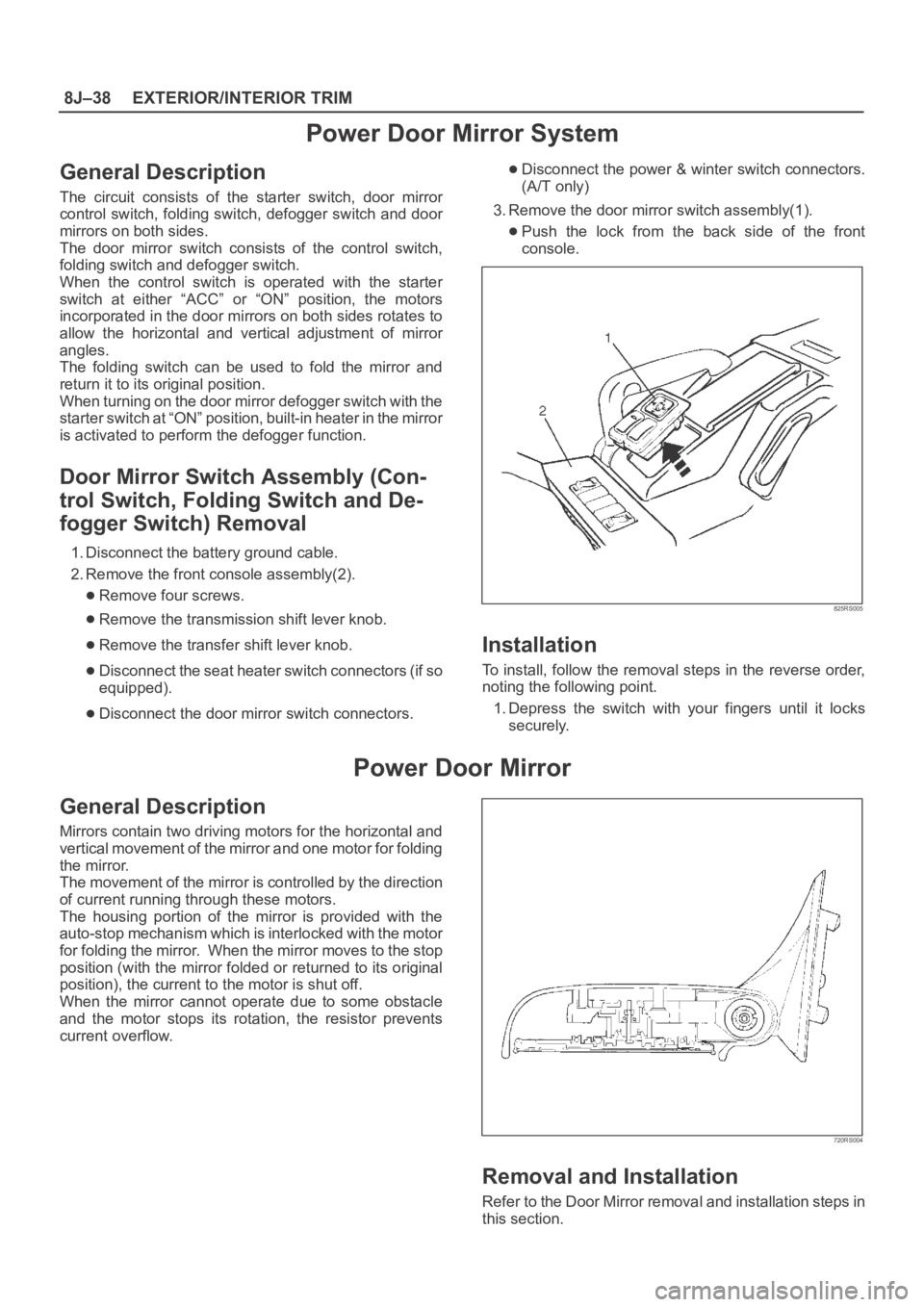
Door Mirror Switch Assembly (Con-
trol Switch, Folding Switch and De-
fogger Switch) Removal
1. Disconnect the battery ground cable.
2. Remove the front console assembly(2).
Remove four screws.
Remove the transmission shift lever knob.
Remove the transfer shift lever knob.
Disconnect the seat heater switch connectors (if so
equipped).
Disconnect the door mirror switch connectors.
Disconnect the power & winter switch connectors.
(A/T only)
3. Remove the door mirror switch assembly(1).
Push the lock from the back side of the front
console.
825RS005
Installation
To install, follow the removal steps in the reverse order,
noting the following point.
1. Depress the switch with your fingers until it locks
securely.
Power Door Mirror
General Description
Mirrors contain two driving motors for the horizontal and
vertical movement of the mirror and one motor for folding
the mirror.
The movement of the mirror is controlled by the direction
of current running through these motors.
The housing portion of the mirror is provided with the
auto-stop mechanism which is interlocked with the motor
for folding the mirror. When the mirror moves to the stop
position (with the mirror folded or returned to its original
position), the current to the motor is shut off.
When the mirror cannot operate due to some obstacle
and the motor stops its rotation, the resistor prevents
current overflow.
720RS004
Removal and Installation
Refer to the Door Mirror removal and installation steps in
this section.
Page 3420 of 6000
EXTERIOR/INTERIOR TRIM8J–41
Main Data and Specifications
Torque Specifications
ApplicationNꞏmkgꞏmlb ftlb in
Door Mirror Fixing Bolts80.8—69
Seat Belt Anchor Bolts394.029—
Hook Fixing Bolt131.3—11 3
Page 4335 of 6000

4D2–28
TRANSFER CASE (TOD)
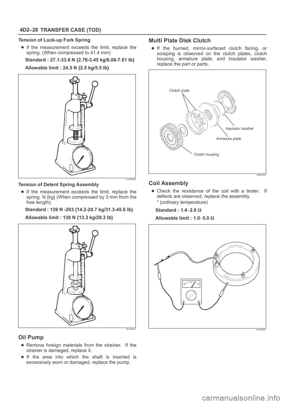
Tension of Lock-up Fork Spring
If the measurement exceeds the limit, replace the
spring. (When compressed to 41.4 mm)
Standard : 27.1-33.8 N {2.76-3.45 kg/6.08-7.61 Ib}
Allowable limit : 24.5 N {2.5 kg/5.5 Ib}
014RW048
Tension of Detent Spring Assembly
If the measurement exceeds the limit, replace the
spring. N {kg} (When compressed by 3 mm from the
free length)
Standard : 139 N -203 {14.2-20.7 kg/31.3-45.6 Ib}
Allowable limit : 130 N {13.3 kg/29.3 Ib}
261RW041
Oil Pump
Remove foreign materials from the strainer. If the
strainer is damaged, replace it.
If the area into which the shaft is inserted is
excessively worn or damaged, replace the pump.
Multi Plate Disk Clutch
If the burned, mirror-surfaced clutch facing, or
scraping is observed on the clutch plates, clutch
housing, armature plate, and insulator washer,
replace the part or parts.
266RW003
Coil Assembly
Check the resistance of the coil with a tester. If
defects are observed, replace the assembly.
* (ordinary temperature)
Standard : 1.4
2.0
Allowable limit : 1.05.0
261RW031