Page 3370 of 6000

SUN ROOF/CONVERTIBLE TOP8I–3
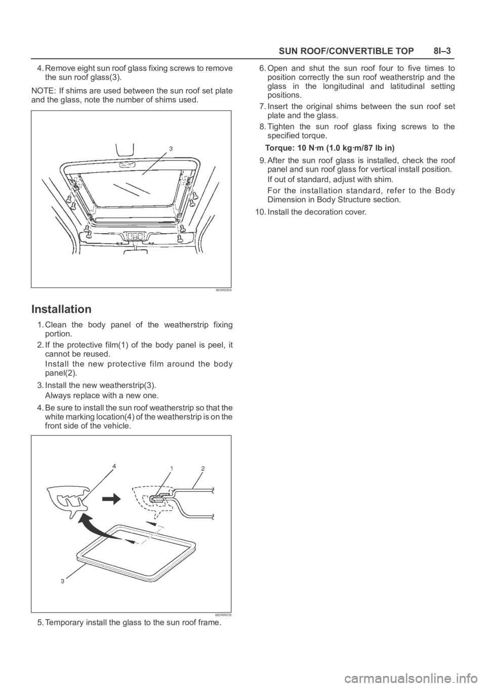
4. Remove eight sun roof glass fixing screws to remove
the sun roof glass(3).
NOTE: If shims are used between the sun roof set plate
and the glass, note the number of shims used.
665RS004
Installation
1. Clean the body panel of the weatherstrip fixing
portion.
2. If the protective film(1) of the body panel is peel, it
cannot be reused.
Install the new protective film around the body
panel(2).
3. Install the new weatherstrip(3).
Always replace with a new one.
4. Be sure to install the sun roof weatherstrip so that the
white marking location(4) of the weatherstrip is on the
front side of the vehicle.
665RW016
5. Temporary install the glass to the sun roof frame.6. Open and shut the sun roof four to five times to
position correctly the sun roof weatherstrip and the
glass in the longitudinal and latitudinal setting
positions.
7. Insert the original shims between the sun roof set
plate and the glass.
8. Tighten the sun roof glass fixing screws to the
specified torque.
Torque: 10 Nꞏm (1.0 kgꞏm/87 lb in)
9. After the sun roof glass is installed, check the roof
panel and sun roof glass for vertical install position.
If out of standard, adjust with shim.
For the installation standard, refer to the Body
Dimension in Body Structure section.
10. Install the decoration cover.
Page 3374 of 6000

SUN ROOF/CONVERTIBLE TOP8I–7
5. Remove two sun roof frame complete assembly fixing
nuts (front side) and four fixing bolts (each side) from
the frame complete, and then remove the sun roof
frame complete assembly.
NOTE: Be sure to remove the frame complete while
supporting it.
Installation
1. Tighten the sun roof frame complete assembly fixing
bolts and nuts to the specified torque.
Torque: 10 Nꞏm(1.0 kgꞏm/87 lb in)2. After installing the frame complete, loosen the sun
roof glass fixing nuts and adjust the sun roof glass
setting position.
Refer to the Sun Roof Glass installation steps in this
section.
3. Install the sun roof drain hose.
4. Install the headlining.
Disassembled View
665RW033
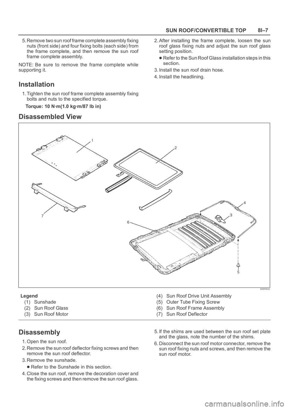
Legend
(1) Sunshade
(2) Sun Roof Glass
(3) Sun Roof Motor(4) Sun Roof Drive Unit Assembly
(5) Outer Tube Fixing Screw
(6) Sun Roof Frame Assembly
(7) Sun Roof Deflector
Disassembly
1. Open the sun roof.
2. Remove the sun roof deflector fixing screws and then
remove the sun roof deflector.
3. Remove the sunshade.
Refer to the Sunshade in this section.
4. Close the sun roof, remove the decoration cover and
the fixing screws and then remove the sun roof glass.5. If the shims are used between the sun roof set plate
and the glass, note the number of the shims.
6. Disconnect the sun roof motor connector, remove the
sun roof fixing nuts and screws, and then remove the
sun roof motor.
Page 3379 of 6000
8I–12SUN ROOF/CONVERTIBLE TOP
Sun Roof Motor
Removal
1. Disconnect the battery ground cable.
2. Remove the headlining(2).
Refer to the Headlining removal steps in Body
Structure section.
3. Disconnect the connector, and remove three nuts and
two screws to remove the sun roof motor(1).
665RS027
Installation
To install, follow the removal steps in the reverse order.
Main Data and Specifications
Torque Specifications
ApplicationNꞏmkgꞏmlb ftlb in
Sun Roof Frame Complete Assembly Fixing Bolts101.0—87
Sun Roof Glass Fixing Screws101.0—87
Page 3381 of 6000

8J–2EXTERIOR/INTERIOR TRIM
Quarter Flipper Glass Assembly (SꞏWꞏB) 8J–33. . .
Quarter Flipper Glass Assembly and
Associated Parts 8J–33. . . . . . . . . . . . . . . . . . . . . .
Removal 8J–33. . . . . . . . . . . . . . . . . . . . . . . . . . . . .
Installation 8J–33. . . . . . . . . . . . . . . . . . . . . . . . . . . .
Tailgate Trim Panel (LH) 8J–34. . . . . . . . . . . . . . . . .
Tailgate Trim Panel (LH) and Associated
Parts 8J–34. . . . . . . . . . . . . . . . . . . . . . . . . . . . . . . .
Removal 8J–34. . . . . . . . . . . . . . . . . . . . . . . . . . . . .
Installation 8J–35. . . . . . . . . . . . . . . . . . . . . . . . . . . .
Tailgate Trim Panel (RH) 8J–36. . . . . . . . . . . . . . . . .
Parts Location 8J–36. . . . . . . . . . . . . . . . . . . . . . . .
Removal 8J–36. . . . . . . . . . . . . . . . . . . . . . . . . . . . .
Installation 8J–36. . . . . . . . . . . . . . . . . . . . . . . . . . . .
Luggage Floor Box 8J–37. . . . . . . . . . . . . . . . . . . . . .
Luggage Floor Box and Associated Parts 8J–37.
Remove 8J–37. . . . . . . . . . . . . . . . . . . . . . . . . . . . . .
Installation 8J–37. . . . . . . . . . . . . . . . . . . . . . . . . . . .
Rope Hook Set 8J–37. . . . . . . . . . . . . . . . . . . . . . . . . Rope Hook Set and Associated Parts 8J–37. . . .
Removal 8J–37. . . . . . . . . . . . . . . . . . . . . . . . . . . . .
Installation 8J–37. . . . . . . . . . . . . . . . . . . . . . . . . . . .
Power Door Mirror System 8J–38. . . . . . . . . . . . . . .
General Description 8J–38. . . . . . . . . . . . . . . . . . . . . .
Door Mirror Switch Assembly (Control Switch, Fold-
ing Switch and Defogger Switch) Removal 8J–38
Installation 8J–38. . . . . . . . . . . . . . . . . . . . . . . . . . . .
Power Door Mirror 8J–38. . . . . . . . . . . . . . . . . . . . . . .
General Description 8J–38. . . . . . . . . . . . . . . . . . . .
Removal and Installation 8J–38. . . . . . . . . . . . . . .
Power Window System 8J–39. . . . . . . . . . . . . . . . . .
General Description 8J–39. . . . . . . . . . . . . . . . . . . . . .
Power Window Switch Removal and
Installation 8J–39. . . . . . . . . . . . . . . . . . . . . . . . . . .
Power Window Motor Removal and
Installation 8J–40. . . . . . . . . . . . . . . . . . . . . . . . . . .
Main Data and Specifications 8J–41. . . . . . . . . . . . .
Service Precaution
WARNING: IF SO EQUIPPED WITH A
SUPPLEMENTAL RESTRAINT SYSTEM (SRS),
REFER TO THE SRS COMPONENT AND WIRING
LOCATION VIEW IN ORDER TO DETERMINE
WHETHER YOU ARE PERFORMING SERVICE ON OR
NEAR THE SRS COMPONENTS OR THE SRS
WIRING. WHEN YOU ARE PERFORMING SERVICE
ON OR NEAR THE SRS COMPONENTS OR THE SRS
WIRING, REFER TO THE SRS SERVICE
INFORMATION. FAILURE TO FOLLOW WARNINGS
COULD RESULT IN POSSIBLE AIR BAG
DEPLOYMENT, PERSONAL INJURY, OR
OTHERWISE UNNEEDED SRS SYSTEM REPAIRS.
CAUTION: Always use the correct fastener in the
proper location. When you replace a fastener, use
ONLY the exact part number for that application.
ISUZU will call out those fasteners that require a
replacement after removal. ISUZU will also call out
the fasteners that require thread lockers or thread
sealant. UNLESS OTHERWISE SPECIFIED, do not
use supplemental coatings (Paints, greases, or other
corrosion inhibitors) on threaded fasteners or
fastener joint interfaces. Generally, such coatings
adversely affect the fastener torque and the joint
clamping force, and may damage the fastener. When
you install fasteners, use the correct tightening
sequence and specifications. Following these
instructions can help you avoid damage to parts and
systems.
Page 3392 of 6000
EXTERIOR/INTERIOR TRIM8J–13
Door Mirror
Door Mirror and Associated Parts
720RS012
Legend
(1) Door Mirror Cover
(2) Door Mirror Connector
(3) Door Mirror
Removal
1. Disconnect the battery ground cable.
2. Remove the door mirror cover(1).
720RW011
3. Remove the door mirror connector.
4. Remove the door mirror.
Installation
To install, follow the removal steps in the reverse order,
noting the following points.
1. When you install the door mirror, install the bolt(1) to
the mirror temporarily, hook the bolt to the door side
hole and tighten the bolt from the inside.
720RS001
2. When installing the door mirror, hold the glass run
lip(2) between the door mirror base(3) and the center
sash(4).
A10RS001
3. Tighten the door mirror fixing bolts to the specified
torque.
Torque: 8 Nꞏm (0.8kgꞏm/69 lb in)
Page 3395 of 6000
8J–16EXTERIOR/INTERIOR TRIM
14. Remove the quarter upper trim cover.
Remove the rear side clips of the trim cover and pry
the quarter upper trim cover retainers free from the
body panel.
687RS004
Installation
To install, follow the removal steps in the reverse order,
noting the following point.
1. Tighten the seat belt anchor bolt to the specified
torque.
Torque: 39 Nꞏm (4.0kgꞏm/29 lb ft)
Page 3398 of 6000
EXTERIOR/INTERIOR TRIM8J–19
10. Remove the rear seat belt anchor bolt cover (1) and
the anchor bolt (2).
755RW037
11. Remove the front seat belt anchor bolt cover (3) and
the anchor bolt (4).
760RW006
12. Remove the quarter upper trim cover.
Remove the rear side clips of the trim cover and pry
the quarter upper trim cover retainers free from the
body panel.
687RW001
13. Remove the seat belt adjust shoulder anchor plate.
Installation
To install, follow the removal steps in the reverse order,
noting the following point.
1. Tighten the seat belt anchor bolts to the specified
torque.
Torque: 39 Nꞏm (4.0kgꞏm/29 lb ft)
Page 3400 of 6000
EXTERIOR/INTERIOR TRIM8J–21
4. Remove the front seat belt anchor bolt cover (3) and
the anchor bolt (4).
760RW006
5. Remove the center pillar upper trim cover (6).
Turn up the finisher (5) and pry the trim cover
retainers free from the body panel.
643RS004
6. Remove the center pillar assist grip.
7. Remove the seat belt anchor plate/adjusut shoulder
anchor assembly.8. Remove the assist grip (7).
Open the both side of the assist grip cover (8) and
remove two fixing screws.
743RW004
9. Remove the roof side trim cover (9).
Turn up the finisher (10) and pry the trim cover
retainers free from the body panel.
643RS005
Installation
To install, follow the removal steps in the reverse order,
noting the following point.
1. Install the seat belt anchor bolts to the specified
torque.
Torque: 39 Nꞏm (4.0kgꞏm/29 lb ft)