Page 1387 of 6000

6E–270
ENGINE DRIVEABILITY AND EMISSIONS
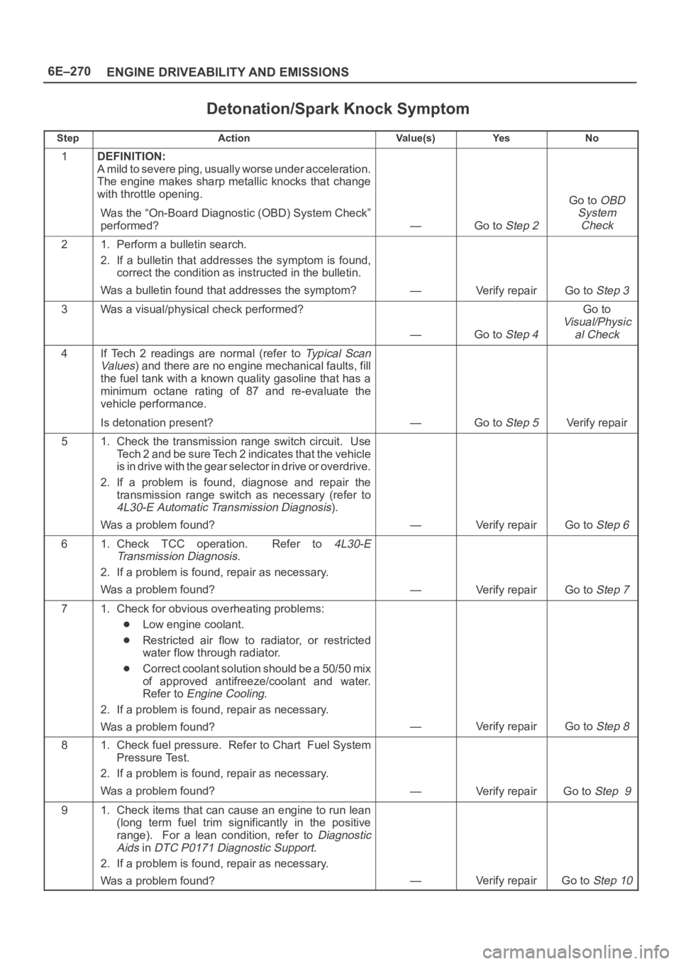
Detonation/Spark Knock Symptom
StepActionVa l u e ( s )Ye sNo
1DEFINITION:
A mild to severe ping, usually worse under acceleration.
The engine makes sharp metallic knocks that change
with throttle opening.
Was the “On-Board Diagnostic (OBD) System Check”
performed?
—Go to Step 2
Go to OBD
System
Check
21. Perform a bulletin search.
2. If a bulletin that addresses the symptom is found,
correct the condition as instructed in the bulletin.
Was a bulletin found that addresses the symptom?
—Verify repairGo to Step 3
3Was a visual/physical check performed?
—Go to Step 4
Go to
Visual/Physic
al Check
4If Tech 2 readings are normal (refer to Ty p i c a l S c a n
Va lu es
) and there are no engine mechanical faults, fill
the fuel tank with a known quality gasoline that has a
minimum octane rating of 87 and re-evaluate the
vehicle performance.
Is detonation present?
—Go to Step 5Verify repair
51. Check the transmission range switch circuit. Use
Tech 2 and be sure Tech 2 indicates that the vehicle
is in drive with the gear selector in drive or overdrive.
2. If a problem is found, diagnose and repair the
transmission range switch as necessary (refer to
4L30-E Automatic Transmission Diagnosis).
Was a problem found?
—Verify repairGo to Step 6
61. Check TCC operation. Refer to 4L30-E
Transmission Diagnosis
.
2. If a problem is found, repair as necessary.
Was a problem found?
—Verify repairGo to Step 7
71. Check for obvious overheating problems:
Low engine coolant.
Restricted air flow to radiator, or restricted
water flow through radiator.
Correct coolant solution should be a 50/50 mix
of approved antifreeze/coolant and water.
Refer to
Engine Cooling.
2. If a problem is found, repair as necessary.
Was a problem found?
—Verify repairGo to Step 8
81. Check fuel pressure. Refer to Chart Fuel System
Pressure Test.
2. If a problem is found, repair as necessary.
Was a problem found?
—Verify repairGo to Step 9
91. Check items that can cause an engine to run lean
(long term fuel trim significantly in the positive
range). For a lean condition, refer to
Diagnostic
Aids
in DTC P0171 Diagnostic Support.
2. If a problem is found, repair as necessary.
Was a problem found?
—Verify repairGo to Step 10
Page 1409 of 6000

6E–292
ENGINE DRIVEABILITY AND EMISSIONS
Crankshaft Position (CKP)
Sensor
Removal Procedure
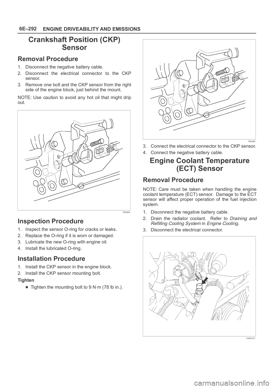
1. Disconnect the negative battery cable.
2. Disconnect the electrical connector to the CKP
sensor.
3. Remove one bolt and the CKP sensor from the right
side of the engine block, just behind the mount.
NOTE: Use caution to avoid any hot oil that might drip
out.
TS22909
Inspection Procedure
1. Inspect the sensor O-ring for cracks or leaks.
2. Replace the O-ring if it is worn or damaged.
3. Lubricate the new O-ring with engine oil.
4. Install the lubricated O-ring.
Installation Procedure
1. Install the CKP sensor in the engine block.
2. Install the CKP sensor mounting bolt.
Tighten
Tighten the mounting bolt to 9 Nꞏm (78 lb in.).
TS22909
3. Connect the electrical connector to the CKP sensor.
4. Connect the negative battery cable.
Engine Coolant Temperature
(ECT) Sensor
Removal Procedure
NOTE: Care must be taken when handling the engine
coolant temperature (ECT) sensor. Damage to the ECT
sensor will affect proper operation of the fuel injection
system.
1. Disconnect the negative battery cable.
2. Drain the radiator coolant. Refer to
Draining and
Refilling Cooling System
in Engine Cooling.
3. Disconnect the electrical connector.
014RW127
Page 1410 of 6000
6E–293 ENGINE DRIVEABILITY AND EMISSIONS
4. Remove the ECT sensor from the coolant crossover.
014RW086
Installation Procedure
1. Apply sealer or the equivalent to the threads of the
ECT sensor.
2. Install the ECT sensor in the coolant crossover.
Tighten
Tighten the ECT sensor to 30 Nꞏm (22 lb ft.).
014RW086
3. Connect the electrical connector.
014RW085
4. Fill the radiator with coolant. Refer to Draining and
Refilling Cooling System
in Engine Cooling.
5. Connect the negative battery cable.
Heated Oxygen Sensor (HO2S)
Removal Procedure
1. Disconnect the negative battery cable.
2. Locate the oxygen sensors.
Bank 1 sensor 1 is mounted on the right-hand front
exhaust pipe.
TS22912
Page 1486 of 6000

6G–7 ENGINE LUBRICATION
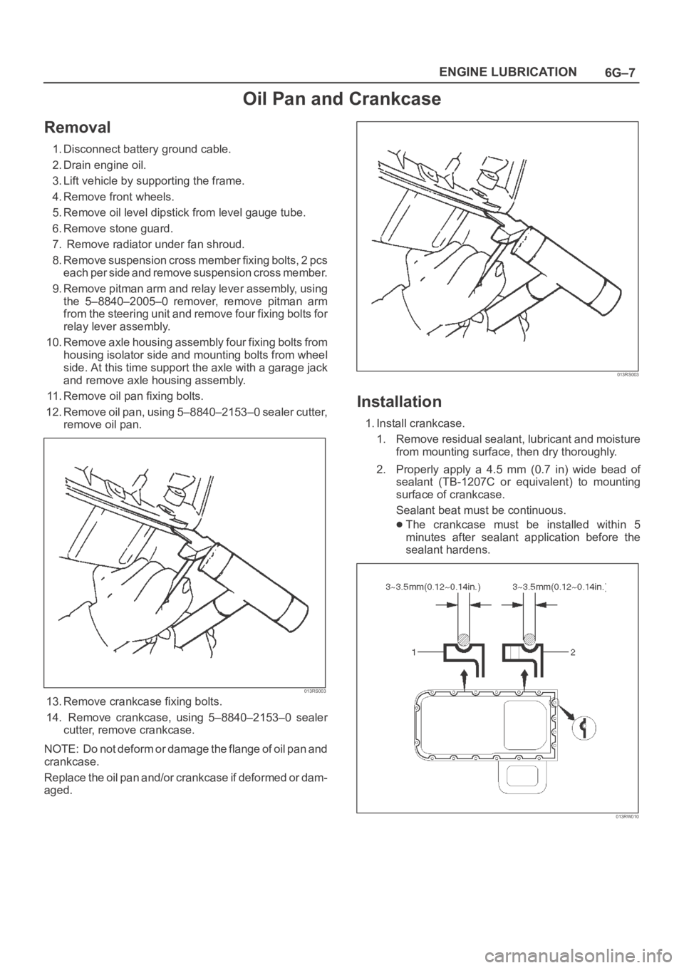
Oil Pan and Crankcase
Removal
1. Disconnect battery ground cable.
2. Drain engine oil.
3. Lift vehicle by supporting the frame.
4. Remove front wheels.
5. Remove oil level dipstick from level gauge tube.
6. Remove stone guard.
7. Remove radiator under fan shroud.
8. Remove suspension cross member fixing bolts, 2 pcs
each per side and remove suspension cross member.
9. Remove pitman arm and relay lever assembly, using
the 5–8840–2005–0 remover, remove pitman arm
from the steering unit and remove four fixing bolts for
relay lever assembly.
10. Remove axle housing assembly four fixing bolts from
housing isolator side and mounting bolts from wheel
side. At this time support the axle with a garage jack
and remove axle housing assembly.
11. Remove oil pan fixing bolts.
12. Remove oil pan, using 5–8840–2153–0 sealer cutter,
remove oil pan.
013RS003
13. Remove crankcase fixing bolts.
14. Remove crankcase, using 5–8840–2153–0 sealer
cutter, remove crankcase.
NOTE: Do not deform or damage the flange of oil pan and
crankcase.
Replace the oil pan and/or crankcase if deformed or dam-
aged.
013RS003
Installation
1. Install crankcase.
1. Remove residual sealant, lubricant and moisture
from mounting surface, then dry thoroughly.
2. Properly apply a 4.5 mm (0.7 in) wide bead of
sealant (TB-1207C or equivalent) to mounting
surface of crankcase.
Sealant beat must be continuous.
The crankcase must be installed within 5
minutes after sealant application before the
sealant hardens.
013RW010
Page 1488 of 6000
6G–9 ENGINE LUBRICATION
6. Install suspension cross member and tighten fixing
bolts to the specified torque.
Torque : 78 Nꞏm (8.0 Kgꞏm/58 lb ft)
013RW007
7. Install radiator under fan shroud.
8. Install stone guard.
9. Install engine oil level dipstick.
10. Fill engine oil until full level on engine oil gauge
dipstick.
Page 1737 of 6000

6A – 4 ENGINE MECHANICAL
Engine Cooling
Starting System
Cooling system Coolant forced circulation
Radiator (2 tube in row) Tube type corrugated
Heat radiation capacity J/h (kcal/h) 318 x 10
6(76000)
Heat radiation area m
2(ft2) 15.63 (1.454)
Front area m
2(ft2) 0.309 (2.029)
Dry weight N (kg/lb) 83 (8.5/18.7)
Radiator cap
Valve opening pressure kPa (kg/cm
2/ psi) 93.3 – 122.7 (0.95 – 1.25/13.5 – 17.8)
Coolant capacity lit (Imp.qt./US qt.) M/T 2.5 (2.2/2.6) A/T 2.4 (2.1/2.5)
Coolant pump Centrifugal impeller type
Pulley ratio (to 1) 1.2
Coolant total capacity lit (Imp.qt./US qt.) 9.3 (8.2/9.8)
Model HITACHI S14-0
Rating
Vo l t a ge V 1 2
Output kW 2.8
Time sec 30
Number of teeth of pinion 9
Rotating direction (as viewed from pinion) Clockwise
Weight (approx.) N(kg/lb) 49 (5.0/11)
No-load characteristics
Voltage/current V/A 11/160 or less
Speed rpm 4000 or more
Load characteristics
Voltage/current V/A 8.76/300
Torque Nꞏm(kgꞏm/lbꞏft) 7.4 (0.75/5.4) or more
Speed rpm 1700 or more
Locking characteristics
Voltage/current V/A 2.5/1100 or less
Torque Nꞏm(kgꞏm/lbꞏft) 18.6 (1.9/14) or more
Page 1741 of 6000
6A – 8 ENGINE MECHANICAL
Parts Items Service standard Service limit Remarks
Cylinder
Block—
95.421 – 95.450
(3.7567 – 3.7579)0.20 (0.0079) Warpage
(Upper surface of the cylinder block)
Cylinder bore diameter
Parts Items Service standard Service limit Remarks
Thermostat
Radiator cap83 – 87°C
(181 – 189°F)
More than 9.5 (0.374)
at 100°C (212°F)
88.2 – 117.6 kPa
(12.8 –17.0 psi) Valve opening temperature
Valve full open temperature and lift
Valve opening pressure
Engine Coolingmm (in) mm (in)
Page 1743 of 6000

6A – 10 ENGINE MECHANICAL
8. Check the engine oil level and replenish to the
specified level if required.
9. Start the engine and check for oil leakage from the
main oil filter.
FUEL SYSTEM
Fuel filter
Replacement Procedure
1. Loosen the used fuel filter by turning it
counterclockwise with the filter wrench.
Filter Wrench : 5-8840-0203-0
2. Clean the filter cover fitting faces.
This will allow the new fuel filter to seat properly.
3. Apply a light coat of engine oil to the O-ring.
4. Turn the fuel filter until the sealing face comes in
contact with the O-ring.
5. Turn the fuel filter with a filter wrench 2/3 of a turn
until sealed.
Filter Wrench: 5-8840-0203-0Legend
(1) Priming pump
6. Operate the priming pump until the air is discharged
completely from fuel system.
NOTE: The use of an Isuzu genuine fuel filter is
strongly recommended.
COOLING SYSTEM
Coolant Level
Check the coolant level and replenish the radiator
reserve tank as necessary.
If the coolant level falls below the “‘MIN” line, carefully
check the cooling system for leakage. Then add
enough coolant to bring the level up to the “MAX” line.
NOTE: Do not overfill the reserve tank.
012RW112
012RW078
1
012RW111
012RW080