1998 OPEL FRONTERA coolant
[x] Cancel search: coolantPage 1120 of 6000
6E–3 ENGINE DRIVEABILITY AND EMISSIONS
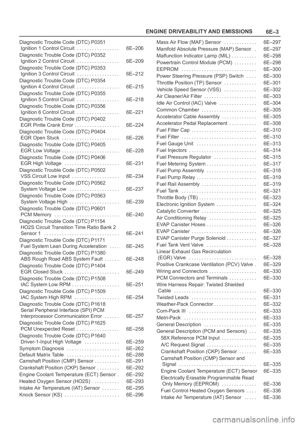
Diagnostic Trouble Code (DTC) P0351
Ignition 1 Control Circuit 6E–206. . . . . . . . . . . . . . . . .
Diagnostic Trouble Code (DTC) P0352
Ignition 2 Control Circuit 6E–209. . . . . . . . . . . . . . . . .
Diagnostic Trouble Code (DTC) P0353
Ignition 3 Control Circuit 6E–212. . . . . . . . . . . . . . . . .
Diagnostic Trouble Code (DTC) P0354
Ignition 4 Control Circuit 6E–215. . . . . . . . . . . . . . . . .
Diagnostic Trouble Code (DTC) P0355
Ignition 5 Control Circuit 6E–218. . . . . . . . . . . . . . . . .
Diagnostic Trouble Code (DTC) P0356
Ignition 6 Control Circuit 6E–221. . . . . . . . . . . . . . . . .
Diagnostic Trouble Code (DTC) P0402
EGR Pintle Crank Error 6E–224. . . . . . . . . . . . . . . . . .
Diagnostic Trouble Code (DTC) P0404
EGR Open Stuck 6E–226. . . . . . . . . . . . . . . . . . . . . . .
Diagnostic Trouble Code (DTC) P0405
EGR Low Voltage 6E–228. . . . . . . . . . . . . . . . . . . . . . .
Diagnostic Trouble Code (DTC) P0406
EGR High Voltage 6E–231. . . . . . . . . . . . . . . . . . . . . .
Diagnostic Trouble Code (DTC) P0502
VSS Circuit Low Input 6E–234. . . . . . . . . . . . . . . . . . .
Diagnostic Trouble Code (DTC) P0562
System Voltage Low 6E–237. . . . . . . . . . . . . . . . . . . .
Diagnostic Trouble Code (DTC) P0563
System Voltage High 6E–239. . . . . . . . . . . . . . . . . . . .
Diagnostic Trouble Code (DTC) P0601
PCM Memory 6E–240. . . . . . . . . . . . . . . . . . . . . . . . . .
Diagnostic Trouble Code (DTC) P1154
HO2S Circuit Transition Time Ratio Bank 2
Sensor 1 6E–241. . . . . . . . . . . . . . . . . . . . . . . . . . . . . .
Diagnostic Trouble Code (DTC) P1171
Fuel System Lean During Acceleration 6E–245. . . .
Diagnostic Trouble Code (DTC) P1380
ABS Rough Road ABS System Fault 6E–248. . . . . .
Diagnostic Trouble Code (DTC) P1404
EGR Closed Stuck 6E–249. . . . . . . . . . . . . . . . . . . . . .
Diagnostic Trouble Code (DTC) P1508
IAC System Low RPM 6E–251. . . . . . . . . . . . . . . . . . .
Diagnostic Trouble Code (DTC) P1509
IAC System High RPM 6E–254. . . . . . . . . . . . . . . . . .
Diagnostic Trouble Code (DTC) P1618
Serial Peripheral Interface (SPI) PCM
Interprocessor Communication Error 6E–257. . . . . .
Diagnostic Trouble Code (DTC) P1625
PCM Unexpected Reset 6E–258. . . . . . . . . . . . . . . . .
Diagnostic Trouble Code (DTC) P1640
Driver-1-Input High Voltage 6E–259. . . . . . . . . . . . . .
Symptom Diagnosis 6E–262. . . . . . . . . . . . . . . . . . . . .
Default Matrix Table 6E–288. . . . . . . . . . . . . . . . . . . . .
Camshaft Position (CMP) Sensor 6E–291. . . . . . . . . .
Crankshaft Position (CKP) Sensor 6E–292. . . . . . . . .
Engine Coolant Temperature (ECT) Sensor 6E–292.
Heated Oxygen Sensor (HO2S) 6E–293. . . . . . . . . . .
Intake Air Temperature (IAT) Sensor 6E–295. . . . . . .
Knock Sensor (KS) 6E–296. . . . . . . . . . . . . . . . . . . . . . Mass Air Flow (MAF) Sensor 6E–297. . . . . . . . . . . . .
Manifold Absolute Pressure (MAP) Sensor 6E–297.
Malfunction Indicator Lamp (MIL) 6E–298. . . . . . . . . .
Powertrain Control Module (PCM) 6E–298. . . . . . . . .
EEPROM 6E–300. . . . . . . . . . . . . . . . . . . . . . . . . . . . . .
Power Steering Pressure (PSP) Switch 6E–300
. . . .
Throttle Position (TP) Sensor 6E–301. . . . . . . . . . . . .
Vehicle Speed Sensor (VSS) 6E–302. . . . . . . . . . . . .
Air Cleaner/Air Filter 6E–303. . . . . . . . . . . . . . . . . . . . .
Idle Air Control (IAC) Valve 6E–304. . . . . . . . . . . . . . .
Common Chamber 6E–305. . . . . . . . . . . . . . . . . . . . . .
Accelerator Cable Assembly 6E–305. . . . . . . . . . . . . .
Accelerator Pedal Replacement 6E–308. . . . . . . . . . .
Fuel Filter Cap 6E–310. . . . . . . . . . . . . . . . . . . . . . . . . .
Fuel Filter 6E–310. . . . . . . . . . . . . . . . . . . . . . . . . . . . . .
Fuel Gauge Unit 6E–313. . . . . . . . . . . . . . . . . . . . . . . .
Fuel Injectors 6E–314. . . . . . . . . . . . . . . . . . . . . . . . . . .
Fuel Pressure Regulator 6E–315. . . . . . . . . . . . . . . . .
Fuel Metering System 6E–317. . . . . . . . . . . . . . . . . . . .
Fuel Pump Assembly 6E–318. . . . . . . . . . . . . . . . . . . .
Fuel Pump Relay 6E–319. . . . . . . . . . . . . . . . . . . . . . . .
Fuel Rail Assembly 6E–319. . . . . . . . . . . . . . . . . . . . . .
Fuel Tank 6E–321. . . . . . . . . . . . . . . . . . . . . . . . . . . . . .
Throttle Body (TB) 6E–323. . . . . . . . . . . . . . . . . . . . . . .
Electronic Ignition System 6E–324. . . . . . . . . . . . . . . .
Catalytic Converter 6E–325. . . . . . . . . . . . . . . . . . . . . .
Air Conditioning Relay 6E–325. . . . . . . . . . . . . . . . . . .
EVAP Canister Hoses 6E–326. . . . . . . . . . . . . . . . . . . .
EVAP Canister 6E–326. . . . . . . . . . . . . . . . . . . . . . . . . .
EVAP Canister Purge Solenoid 6E–327. . . . . . . . . . . .
Fuel Tank Vent Valve 6E–328. . . . . . . . . . . . . . . . . . . .
Linear Exhaust Gas Recirculation
(EGR) Valve 6E–328. . . . . . . . . . . . . . . . . . . . . . . . . . .
Positive Crankcase Ventilation (PCV) Valve 6E–329.
Wiring and Connectors 6E–330. . . . . . . . . . . . . . . . . . .
PCM Connectors and Terminals 6E–330. . . . . . . . . . .
Wire Harness Repair: Twisted Shielded
Cable 6E–330. . . . . . . . . . . . . . . . . . . . . . . . . . . . . . . . .
Twisted Leads 6E–331. . . . . . . . . . . . . . . . . . . . . . . . . .
Weather-Pack Connector 6E–332. . . . . . . . . . . . . . . . .
Com-Pack III 6E–333. . . . . . . . . . . . . . . . . . . . . . . . . . .
Metri-Pack 6E–333. . . . . . . . . . . . . . . . . . . . . . . . . . . . .
General Description 6E–335. . . . . . . . . . . . . . . . . . . . .
General Description (PCM and Sensors) 6E–335. . .
58X Reference PCM Input 6E–335. . . . . . . . . . . . . .
A/C Request Signal 6E–335. . . . . . . . . . . . . . . . . . . .
Crankshaft Position (CKP) Sensor 6E–335. . . . . . .
Camshaft Position (CMP) Sensor and
Signal 6E–335. . . . . . . . . . . . . . . . . . . . . . . . . . . . . . .
Engine Coolant Temperature (ECT) Sensor 6E–335
Electrically Erasable Programmable Read
Only Memory (EEPROM) 6E–336. . . . . . . . . . . . . .
Fuel Control Heated Oxygen Sensors 6E–336. . . .
Intake Air Temperature (IAT) Sensor 6E–336. . . . .
Page 1122 of 6000
6E–5 ENGINE DRIVEABILITY AND EMISSIONS
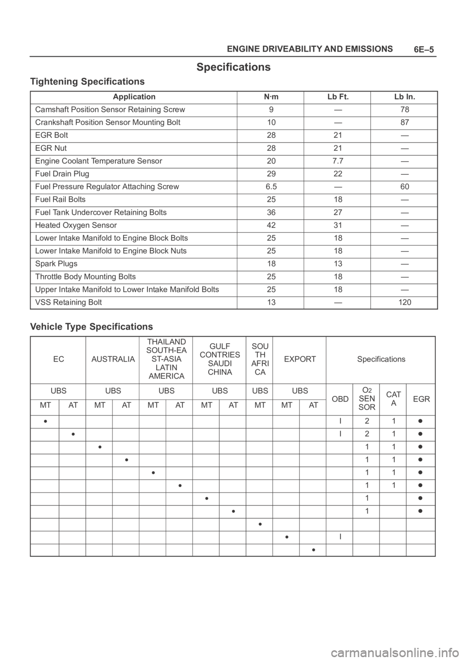
Specifications
Tightening Specifications
ApplicationNꞏmLb Ft.Lb In.
Camshaft Position Sensor Retaining Screw9—78
Crankshaft Position Sensor Mounting Bolt10—87
EGR Bolt2821—
EGR Nut2821—
Engine Coolant Temperature Sensor207.7—
Fuel Drain Plug2922—
Fuel Pressure Regulator Attaching Screw6.5—60
Fuel Rail Bolts2518—
Fuel Tank Undercover Retaining Bolts3627—
Heated Oxygen Sensor4231—
Lower Intake Manifold to Engine Block Bolts2518—
Lower Intake Manifold to Engine Block Nuts2518—
Spark Plugs1813—
Throttle Body Mounting Bolts2518—
Upper Intake Manifold to Lower Intake Manifold Bolts2518—
VSS Retaining Bolt13—120
Vehicle Type Specifications
ECAUSTRALIA
THAILAND
SOUTH-EA
ST-ASIA
LATIN
AMERICAGULF
CONTRIES
SAUDI
CHINASOU
TH
AFRI
CA
EXPORTSpecifications
UBSUBSUBSUBSUBSUBS
OBD
O2
SENCATEGRMTATMTATMTATMTATMTMTATOBDSEN
SORAEGR
I21
I21
11
11
11
11
1
1
I
Page 1141 of 6000
6E–24
ENGINE DRIVEABILITY AND EMISSIONS
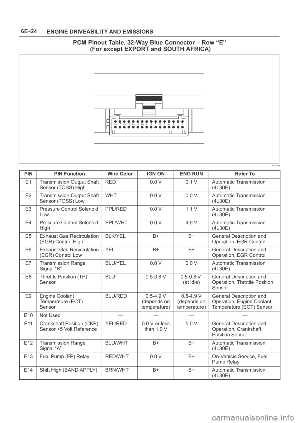
PCM Pinout Table, 32-Way Blue Connector – Row “E”
(For except EXPORT and SOUTH AFRICA)
TS23346
PINPIN FunctionWire ColorIGN ONENG RUNRefer To
E1Transmission Output Shaft
Sensor (TOSS) HighRED0.0 V0.1 VAutomatic Transmission
(4L30E)
E2Transmission Output Shaft
Sensor (TOSS) LowWHT0.0 V0.0 VAutomatic Transmission
(4L30E)
E3Pressure Control Solenoid
LowPPL/RED0.0 V1.1 VAutomatic Transmission
(4L30E)
E4Pressure Control Solenoid
HighPPL/WHT0.0 V4.9 VAutomatic Transmission
(4L30E)
E5Exhaust Gas Recirculation
(EGR) Control HighBLK/YELB+B+General Description and
Operation, EGR Control
E6Exhaust Gas Recirculation
(EGR) Control LowYELB+B+General Description and
Operation, EGR Control
E7Transmission Range
Signal “B”BLU/YEL0.0 V0.0 VAutomatic Transmission
(4L30E)
E8Throttle Position (TP)
SensorBLU0.5-0.8 V0.5-0.8 V
(at idle)General Description and
Operation, Throttle Position
Sensor
E9Engine Coolant
Temperature (ECT)
SensorBLU/RED0.5-4.9 V
(depends on
temperature)0.5-4.9 V
(depends on
temperature)General Description and
Operation, Engine Coolant
Temperature (ECT) Sensor
E10Not Used————
E11Crankshaft Position (CKP)
Sensor +5 Volt ReferenceYEL/RED5.0 V or less
than 1.0 V5.0 VGeneral Description and
Operation, Crankshaft
Position Sensor
E12Transmission Range
Signal “A”BLU/WHTB+B+Automatic Transmission
(4L30E)
E13Fuel Pump (FP) RelayRED/WHT0.0 VB+On-Vehicle Service, Fuel
Pump Relay
E14Shift High (BAND APPLY)BRN/WHTB+B+Automatic Transmission
(4L30E)
Page 1143 of 6000
6E–26
ENGINE DRIVEABILITY AND EMISSIONS
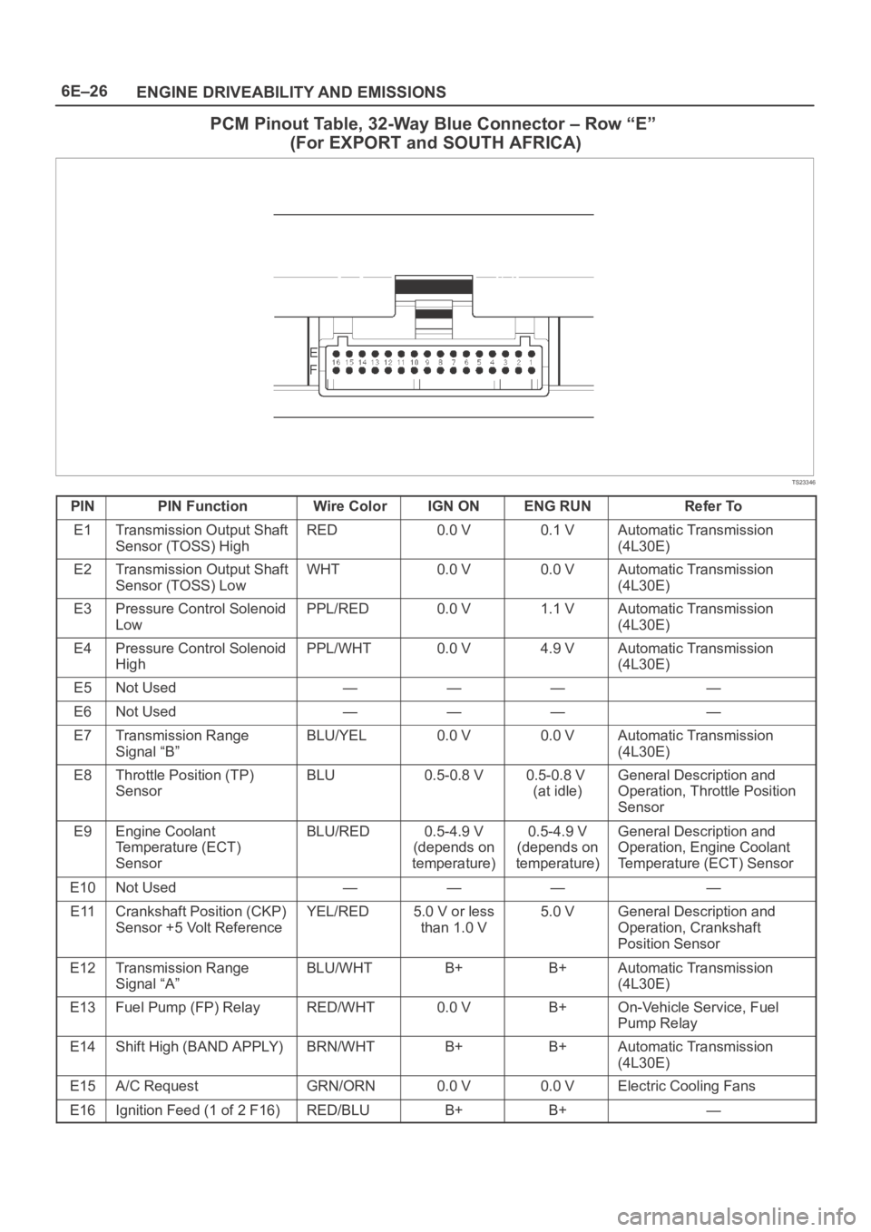
PCM Pinout Table, 32-Way Blue Connector – Row “E”
(For EXPORT and SOUTH AFRICA)
TS23346
PINPIN FunctionWire ColorIGN ONENG RUNRefer To
E1Transmission Output Shaft
Sensor (TOSS) HighRED0.0 V0.1 VAutomatic Transmission
(4L30E)
E2Transmission Output Shaft
Sensor (TOSS) LowWHT0.0 V0.0 VAutomatic Transmission
(4L30E)
E3Pressure Control Solenoid
LowPPL/RED0.0 V1.1 VAutomatic Transmission
(4L30E)
E4Pressure Control Solenoid
HighPPL/WHT0.0 V4.9 VAutomatic Transmission
(4L30E)
E5Not Used————
E6Not Used————
E7Transmission Range
Signal “B”BLU/YEL0.0 V0.0 VAutomatic Transmission
(4L30E)
E8Throttle Position (TP)
SensorBLU0.5-0.8 V0.5-0.8 V
(at idle)General Description and
Operation, Throttle Position
Sensor
E9Engine Coolant
Temperature (ECT)
SensorBLU/RED0.5-4.9 V
(depends on
temperature)0.5-4.9 V
(depends on
temperature)General Description and
Operation, Engine Coolant
Temperature (ECT) Sensor
E10Not Used————
E11Crankshaft Position (CKP)
Sensor +5 Volt ReferenceYEL/RED5.0 V or less
than 1.0 V5.0 VGeneral Description and
Operation, Crankshaft
Position Sensor
E12Transmission Range
Signal “A”BLU/WHTB+B+Automatic Transmission
(4L30E)
E13Fuel Pump (FP) RelayRED/WHT0.0 VB+On-Vehicle Service, Fuel
Pump Relay
E14Shift High (BAND APPLY)BRN/WHTB+B+Automatic Transmission
(4L30E)
E15A/C RequestGRN/ORN0.0 V0.0 VElectric Cooling Fans
E16Ignition Feed (1 of 2 F16)RED/BLUB+B+—
Page 1146 of 6000
6E–29 ENGINE DRIVEABILITY AND EMISSIONS
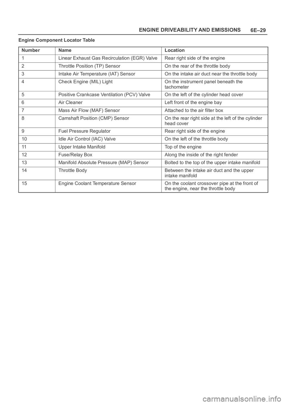
Engine Component Locator Table
Number
NameLocation
1Linear Exhaust Gas Recirculation (EGR) ValveRear right side of the engine
2Throttle Position (TP) SensorOn the rear of the throttle body
3Intake Air Temperature (IAT) SensorOn the intake air duct near the throttle body
4Check Engine (MIL) LightOn the instrument panel beneath the
tachometer
5Positive Crankcase Ventilation (PCV) ValveOn the left of the cylinder head cover
6Air CleanerLeft front of the engine bay
7Mass Air Flow (MAF) SensorAttached to the air filter box
8Camshaft Position (CMP) SensorOn the rear right side at the left of the cylinder
head cover
9Fuel Pressure RegulatorRear right side of the engine
10Idle Air Control (IAC) ValveOn the left of the throttle body
11Upper Intake ManifoldTop of the engine
12Fuse/Relay BoxAlong the inside of the right fender
13Manifold Absolute Pressure (MAP) SensorBolted to the top of the upper intake manifold
14Throttle BodyBetween the intake air duct and the upper
intake manifold
15Engine Coolant Temperature SensorOn the coolant crossover pipe at the front of
the engine, near the throttle body
Page 1148 of 6000
6E–31 ENGINE DRIVEABILITY AND EMISSIONS
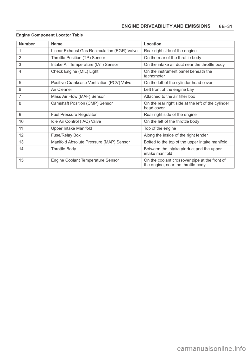
Engine Component Locator Table
Number
NameLocation
1Linear Exhaust Gas Recirculation (EGR) ValveRear right side of the engine
2Throttle Position (TP) SensorOn the rear of the throttle body
3Intake Air Temperature (IAT) SensorOn the intake air duct near the throttle body
4Check Engine (MIL) LightOn the instrument panel beneath the
tachometer
5Positive Crankcase Ventilation (PCV) ValveOn the left of the cylinder head cover
6Air CleanerLeft front of the engine bay
7Mass Air Flow (MAF) SensorAttached to the air filter box
8Camshaft Position (CMP) SensorOn the rear right side at the left of the cylinder
head cover
9Fuel Pressure RegulatorRear right side of the engine
10Idle Air Control (IAC) ValveOn the left of the throttle body
11Upper Intake ManifoldTop of the engine
12Fuse/Relay BoxAlong the inside of the right fender
13Manifold Absolute Pressure (MAP) SensorBolted to the top of the upper intake manifold
14Throttle BodyBetween the intake air duct and the upper
intake manifold
15Engine Coolant Temperature SensorOn the coolant crossover pipe at the front of
the engine, near the throttle body
Page 1156 of 6000
6E–39 ENGINE DRIVEABILITY AND EMISSIONS
The data displayed on the other Tech 2 will appear the
same, with some exceptions. Some Tech 2s will only be
able to display certain vehicle parameters as values that
are a coded representation of the true or actual value. For
more information on this system of coding, refer to
Decimal/Binary/Hexadecimal Conversions. On this
vehicle Tech 2 displays the actual values for vehicle
parameters. It will not be necessary to perform any
conversions from coded values to actual values.
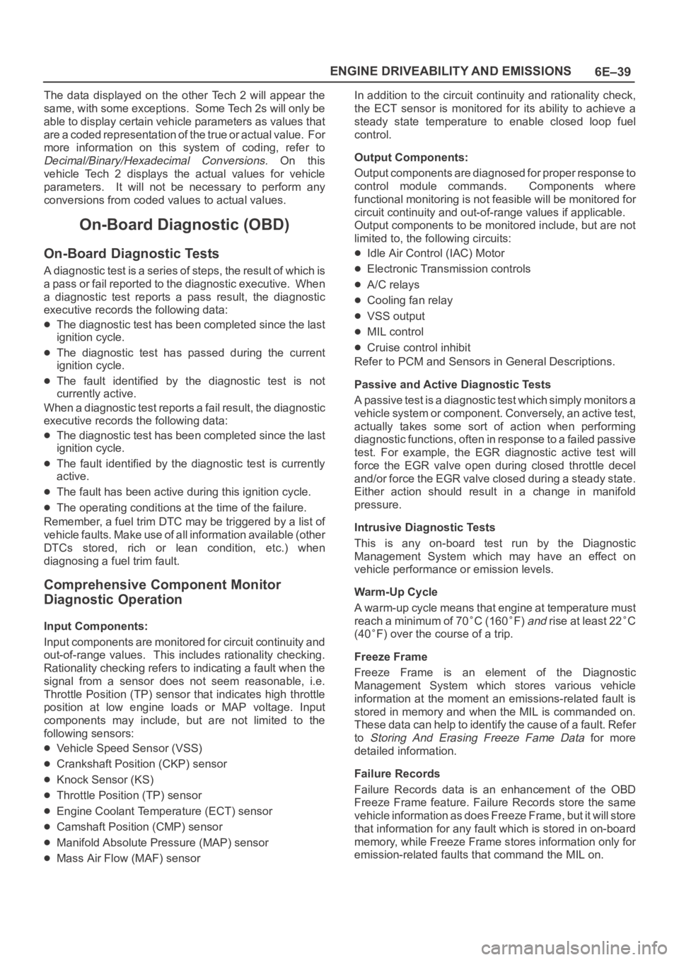
On-Board Diagnostic (OBD)
On-Board Diagnostic Tests
A diagnostic test is a series of steps, the result of which is
a pass or fail reported to the diagnostic executive. When
a diagnostic test reports a pass result, the diagnostic
executive records the following data:
The diagnostic test has been completed since the last
ignition cycle.
The diagnostic test has passed during the current
ignition cycle.
The fault identified by the diagnostic test is not
currently active.
W h e n a d i a g n o s t i c t e s t r e p o r t s a fail result, the diagnostic
executive records the following data:
The diagnostic test has been completed since the last
ignition cycle.
The fault identified by the diagnostic test is currently
active.
The fault has been active during this ignition cycle.
The operating conditions at the time of the failure.
Remember, a fuel trim DTC may be triggered by a list of
vehicle faults. Make use of all information available (other
DTCs stored, rich or lean condition, etc.) when
diagnosing a fuel trim fault.
Comprehensive Component Monitor
Diagnostic Operation
Input Components:
Input components are monitored for circuit continuity and
out-of-range values. This includes rationality checking.
Rationality checking refers to indicating a fault when the
signal from a sensor does not seem reasonable, i.e.
Throttle Position (TP) sensor that indicates high throttle
position at low engine loads or MAP voltage. Input
components may include, but are not limited to the
following sensors:
Vehicle Speed Sensor (VSS)
Crankshaft Position (CKP) sensor
Knock Sensor (KS)
Throttle Position (TP) sensor
Engine Coolant Temperature (ECT) sensor
Camshaft Position (CMP) sensor
Manifold Absolute Pressure (MAP) sensor
Mass Air Flow (MAF) sensorIn addition to the circuit continuity and rationality check,
the ECT sensor is monitored for its ability to achieve a
steady state temperature to enable closed loop fuel
control.
Output Components:
Output components are diagnosed for proper response to
control module commands. Components where
functional monitoring is not feasible will be monitored for
circuit continuity and out-of-range values if applicable.
Output components to be monitored include, but are not
limited to, the following circuits:
Idle Air Control (IAC) Motor
Electronic Transmission controls
A/C relays
Cooling fan relay
VSS output
MIL control
Cruise control inhibit
Refer to PCM and Sensors in General Descriptions.
Passive and Active Diagnostic Tests
A passive test is a diagnostic test which simply monitors a
vehicle system or component. Conversely, an active test,
actually takes some sort of action when performing
diagnostic functions, often in response to a failed passive
test. For example, the EGR diagnostic active test will
force the EGR valve open during closed throttle decel
and/or force the EGR valve closed during a steady state.
Either action should result in a change in manifold
pressure.
Intrusive Diagnostic Tests
This is any on-board test run by the Diagnostic
Management System which may have an effect on
vehicle performance or emission levels.
Warm-Up Cycle
A warm-up cycle means that engine at temperature must
reach a minimum of 70
C (160F) and rise at least 22C
(40
F) over the course of a trip.
Freeze Frame
Freeze Frame is an element of the Diagnostic
Management System which stores various vehicle
information at the moment an emissions-related fault is
stored in memory and when the MIL is commanded on.
These data can help to identify the cause of a fault. Refer
to
Storing And Erasing Freeze Fame Data for more
detailed information.
Failure Records
Failure Records data is an enhancement of the OBD
Freeze Frame feature. Failure Records store the same
vehicle information as does Freeze Frame, but it will store
that information for any fault which is stored in on-board
memory, while Freeze Frame stores information only for
emission-related faults that command the MIL on.
Page 1158 of 6000
6E–41 ENGINE DRIVEABILITY AND EMISSIONS
If the MIL was set by either a fuel trim or misfire-related
DTC, additional requirements must be met. In addition to
the requirements stated in the previous paragraph, these
requirements are as follows:
The diagnostic tests that are passed must occur with
375 RPM of the RPM data stored at the time the last
test failed.
Plus or minus ten (10) percent of the engine load that
was stored at the time the last failed.
Similar engine temperature conditions (warmed up or
warming up ) as those stored at the time the last test
failed.
Meeting these requirements ensures that the fault which
turned on the MIL has been corrected.
The MIL (“Check Engine” lamp) is on the instrument
panel and has the following function:
It informs the driver that a fault affects vehicle emission
levels has occurred and that the vehicle should be
taken for service as soon as possible.
As a bulb and system check, the MIL will come “ON”
with the key “ON” and the engine not running. When
the engine is started, the MIL will turn “OFF.”
When the MIL remains “ON” while the engine is
running, or when a malfunction is suspected due to a
driveability or emissions problem, a Powertrain
On-Board Diagnostic (OBD ll) System Check must be
performed. The procedures for these checks are given
in On-Board Diagnostic (OBD) System Check. These
checks will expose faults which may not be detected if
other diagnostics are performed first.
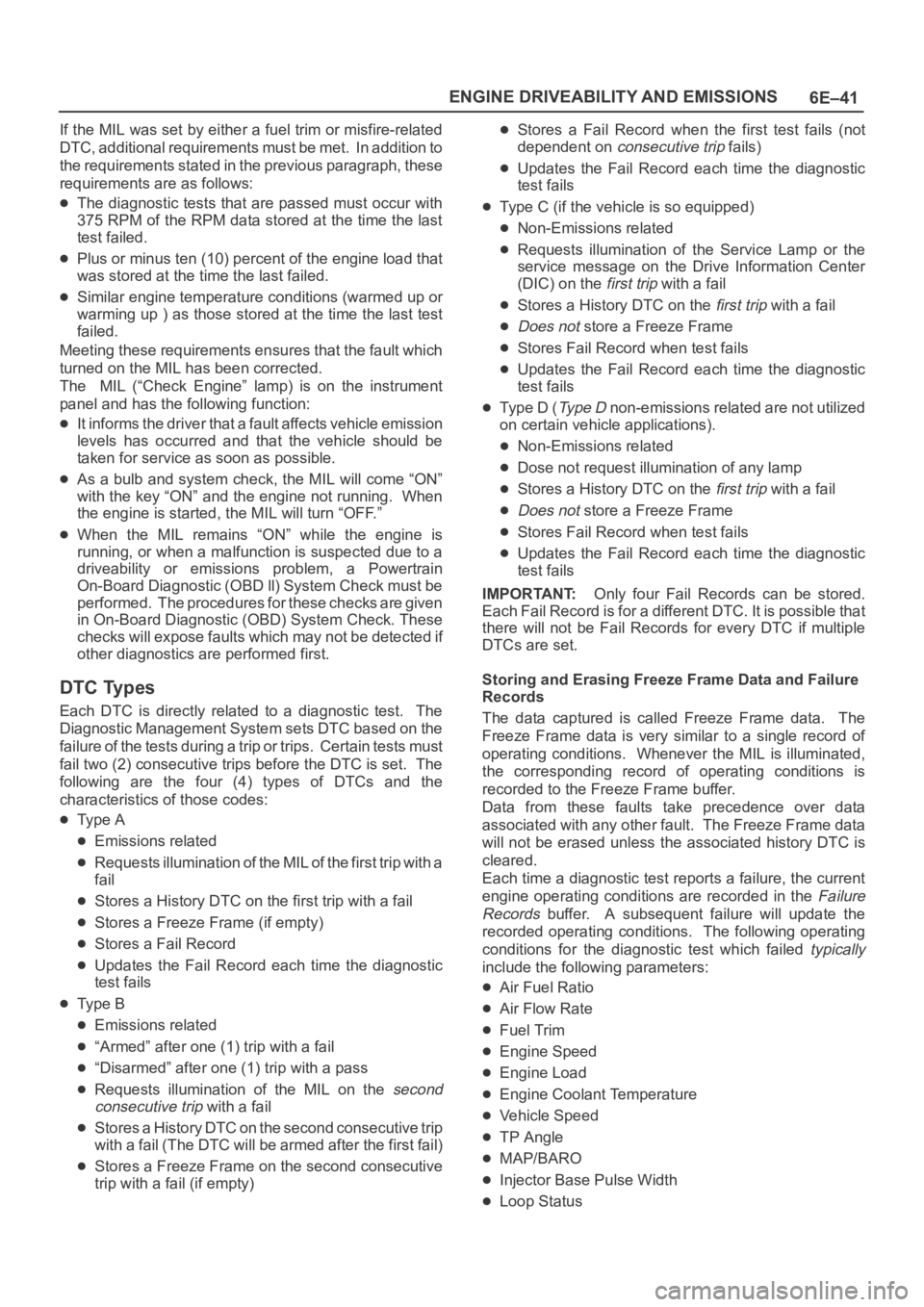
DTC Types
Each DTC is directly related to a diagnostic test. The
Diagnostic Management System sets DTC based on the
failure of the tests during a trip or trips. Certain tests must
fail two (2) consecutive trips before the DTC is set. The
following are the four (4) types of DTCs and the
characteristics of those codes:
Ty p e A
Emissions related
Requests illumination of the MIL of the first trip with a
fail
Stores a History DTC on the first trip with a fail
Stores a Freeze Frame (if empty)
Stores a Fail Record
Updates the Fail Record each time the diagnostic
test fails
Ty p e B
Emissions related
“Armed” after one (1) trip with a fail
“Disarmed” after one (1) trip with a pass
Requests illumination of the MIL on the second
consecutive trip
with a fail
Stores a History DTC on the second consecutive trip
with a fail (The DTC will be armed after the first fail)
Stores a Freeze Frame on the second consecutive
trip with a fail (if empty)
Stores a Fail Record when the first test fails (not
dependent on
consecutive trip fails)
Updates the Fail Record each time the diagnostic
test fails
Type C (if the vehicle is so equipped)
Non-Emissions related
Requests illumination of the Service Lamp or the
service message on the Drive Information Center
(DIC) on the
first trip with a fail
Stores a History DTC on the first trip with a fail
Does not store a Freeze Frame
Stores Fail Record when test fails
Updates the Fail Record each time the diagnostic
test fails
Type D (Ty p e D non-emissions related are not utilized
on certain vehicle applications).
Non-Emissions related
Dose not request illumination of any lamp
Stores a History DTC on the first trip with a fail
Does not store a Freeze Frame
Stores Fail Record when test fails
Updates the Fail Record each time the diagnostic
test fails
IMPORTANT:Only four Fail Records can be stored.
Each Fail Record is for a different DTC. It is possible that
there will not be Fail Records for every DTC if multiple
DTCs are set.
Storing and Erasing Freeze Frame Data and Failure
Records
The data captured is called Freeze Frame data. The
Freeze Frame data is very similar to a single record of
operating conditions. Whenever the MIL is illuminated,
the corresponding record of operating conditions is
recorded to the Freeze Frame buffer.
Data from these faults take precedence over data
associated with any other fault. The Freeze Frame data
will not be erased unless the associated history DTC is
cleared.
Each time a diagnostic test reports a failure, the current
engine operating conditions are recorded in the
Failure
Records
buffer. A subsequent failure will update the
recorded operating conditions. The following operating
conditions for the diagnostic test which failed
typically
include the following parameters:
Air Fuel Ratio
Air Flow Rate
Fuel Trim
Engine Speed
Engine Load
Engine Coolant Temperature
Vehicle Speed
TP Angle
MAP/BARO
Injector Base Pulse Width
Loop Status