Page 3008 of 6000
D08RW729
IJ
0.3
Y/G 0.5
Y/R
0.5
Y/R
BODY-RR
ALARM&RELAY
CONTROL UNIT FUEL
TANK
UNIT
0.5
B
1.25
B 0.5
B/P0.3
Y/BR
0.3
Y/BR
0.3
Y/BR
7
17 144 1
12
B-66B-7
DIMMER•
PASSING
SW FUSE F-4
0.85
R/Y 0.85
R/L
14 15 13
9 I-10 I-10 H-16
H-9 HIGH
BEAM
R-4
F-5
H-332
F-518
H-46
13
H-33
F-5
H-33
H-46
0.5
Y/R
FUEL
TANK
UNIT
0.5
B/P0.3
Y/BR
0.3
Y/BR
179 4 1
19
F-5
H-332
F-57
H-33 (SOUTH AFRICA)
F-5
H-33
H-46
Page 3014 of 6000
D08RW729
IJ
0.3
Y/G 0.5
Y/R
0.5
Y/R
BODY-RR
ALARM&RELAY
CONTROL UNIT FUEL
TANK
UNIT
0.5
B
1.25
B 0.5
B/P0.3
Y/BR
0.3
Y/BR
0.3
Y/BR
7
17 144 1
12
B-66B-7
DIMMER•
PASSING
SW FUSE F-4
0.85
R/Y 0.85
R/L
14 15 13
9 I-10 I-10 H-16
H-9 HIGH
BEAM
R-4
F-5
H-332
F-518
H-46
13
H-33
F-5
H-33
H-46
0.5
Y/R
FUEL
TANK
UNIT
0.5
B/P0.3
Y/BR
0.3
Y/BR
179 4 1
19
F-5
H-332
F-57
H-33 (SOUTH AFRICA)
F-5
H-33
H-46
Page 3020 of 6000
D08RW741
FI
I-1015
F-5FUEL
TA N K
UNIT
2
H-3313
H-4618
B-67B-76
I-10 HIGH
BEAM
H-9
DIMMERꞏ
PA S S I N G
SW14
9
H-16
0.85
R/L
0.5
Y/R0.5
Y/R
0.5
B 0.5
B/P 0.85
R/Y
1.25
B0.3
Y/G
0.3
Y/BR0.3
Y/BR
0.3
Y/BR
ALARM & RELAY
CONTROL UNIT
FUSE F-4
13
F-5
4
H-3314
H-4617
F-5
1
H-3312
R-4
BODY-RR
Page 3028 of 6000
D08RW928
IJ
0.3
Y/G 0.5
Y/R
0.5
Y/R
BODY-RR
ALARM&RELAY
CONTROL UNIT FUEL
TANK
UNIT
0.5
B
1.25
B 0.5
B/P0.3
Y/BR
0.3
Y/BR
0.3
Y/BR
7
17 144 1
12
B-66B-7
FUSE F-4
0.85
R/L 0.85
R/Y
15 14 12
10 I-10 I-10 H-16
H-16
4
C-39 HIGH
BEAMR-4
FENDER-RH
F-5
H-332
F-518
H-46
13
H-33
F-5
H-33
H-460.5
B
Page 3034 of 6000
D08RW918
FI
0.3
Y/G 0.5
Y/R
0.5
Y/R
BODY-RR
ALARM&RELAY
CONTROL UNIT FUEL
TANK
UNIT
0.5
B
1.25
B 0.5
B/P0.3
Y/BR
0.3
Y/BR
0.3
Y/BR
7
17 144 1
12
B-66B-7
DIMMER•
PASSING
SW FUSE F-4
0.85
R/Y 0.85
R/L
14 15 10
12 I-10 I-10 H-16
H-16 HIGH
BEAM
R-4
F-5
H-332
F-518
H-46
13
H-33
F-5
H-33
H-46
Page 3361 of 6000

8H–22SECURITY AND LOCKS
Anti-theft System
General Description
The circuit consists of the starter switch, anti-theft &
keyless entry control unit, anti-theft horn, front door and
tailgate key switch (detect and tamper switch), door lock
(& power window) switch, door lock actuator for each
door, engine hood switch, clutch start switch (M/T),
ANTI-THEFT indicator light and mode switch (A/T).
The system operates as follows: After locking the starter
switch and removing the starter key (this sets the alarm),
if the door is unlocked in any way other than with the
proper key, the headlights start flashing, the horn sounds,
and the starter circuit is disabled. (However, the engine
hood and all the doors must be locked and closed.)
Once the system has been placed in the warning or alarm
condition, it can be released only when the starter switch
is shifted from “OFF” to “ACC” by the starter key, or when
the lock of the front door or the tailgate is released (to
activate the detect switch) by the starter key.
Anti-theft & Keyless Entry Control
Unit Removal
1. Disconnect the battery ground cable.
2. Remove the front console assembly.
Refer to the Instrument Panel Assembly in Body
Structure section.
3. Remove the lower cluster assembly.
Refer to the Instrument Panel Assembly in Body
Structure section.
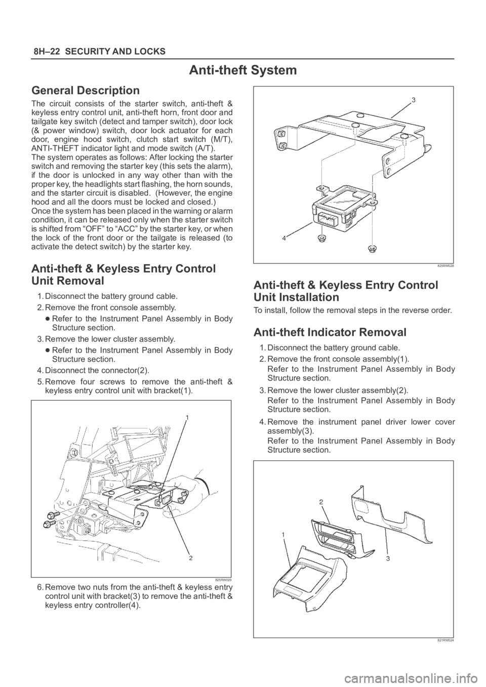
4. Disconnect the connector(2).
5. Remove four screws to remove the anti-theft &
keyless entry control unit with bracket(1).
825RW029
6. Remove two nuts from the anti-theft & keyless entry
control unit with bracket(3) to remove the anti-theft &
keyless entry controller(4).
825RW028
Anti-theft & Keyless Entry Control
Unit Installation
To install, follow the removal steps in the reverse order.
Anti-theft Indicator Removal
1. Disconnect the battery ground cable.
2. Remove the front console assembly(1).
Refer to the Instrument Panel Assembly in Body
Structure section.
3. Remove the lower cluster assembly(2).
Refer to the Instrument Panel Assembly in Body
Structure section.
4. Remove the instrument panel driver lower cover
assembly(3).
Refer to the Instrument Panel Assembly in Body
Structure section.
821RW024
Page 3449 of 6000

SUPPLEMENTAL RESTRAINT SYSTEM 9J–12
Deployed Air Bag Assembly (Driver Side)
“You should wear gloves and glasses. After the air bag
assembly has been deployed, the surface of the air bag
may contain solid particulate. This solid particulate
c o n s i s t s p r i m a r i l y o f b y p r oducts of the chemical reaction,
Potassium Chloride and copper metal dust. Compounds
of Potassium Borate, Strontium Chloride, Copper
Chloride, and Ammonium Chloride may be found in
amounts of about 1% (each) of the total particulate.”
Deployed Pretensioner Seat Belt.
You should wear gloves and safety glasses. After the
pretensioner seat belt has been deployed, the surface of
the pretensioner seat belt cylinder may heating up.
Air Bag Assembly and/or Pretensioner
Seat Belt Scrapping Procedure.
During the cause of vehicle’s useful life, certain situations
may arise which will necessitate the disposal of a live air
bag and/or pretensioner seat belt. (This information
covers proper procedures for disposing of a live air bag
assembly and/or pretensioner seat belt.)
Before a live air bag assembly can be dispose off, it must
be deployed.
A live air bag assembly and/or pretensioner seat belt
must not be disposed of though normal refuse channels.
WARNING: FAILURE TO FOLLOW PROPER
SUPPLEMENTAL RESTRAINT SYSTEM (SRS) AIR
BAG ASSEMBLY DISPOSAL PROCEDURES CAN
RESULT IN AIR BAG DEPLOYMENT WHICH MAY
CAUSE PERSONAL INJURY. AN UNDPLOYED AIR
BAG ASSEMBLY MUST NOT BE DISPOSED OF
THROUGH NORMAL REFUSE CHANNELS. THE
UNDEPLOYED AIR BAG ASSEMBLY CONTAINS
SUBSTANCES THAT CAN CAUSE SEVERE ILLNESS
OR PERSONAL INJURY IF THE SEALED CONTAINER
IS DAMAGED DURING DISPOSAL. DISPOSAL IN
ANY MANNER INCONSISTENT WITH PROPER
PROCEDURES MAY BE A VIOLATION OF LOCAL
LAW.
In situations which require deployment of a live air bag
assembly, deployment may be accomplished inside or
outside the vehicle. The method employed depends
upon the final disposition of the particular vehicle, as
noted in “Deployment Outside Vehicle” and “Deployment
Inside Vehicle” in this section.
Cautions About Air Bag Deployment And
Disposal
Failure to follow proper procedures could result in
erroneous air bag deployment which may cause personal
injury be sure to follow proper procedures.
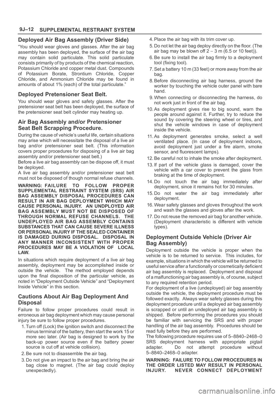
1. Turn off (Lock) the ignition switch and disconnect the
minus terminal of the battery, then start the work 15 or
more sec later. (Air bag is designed to work by the
back-up power source even if the battery power
source is cut off at vehicle collision).
2. Be sure not to disassemble the air bag.
3. Do not give an impact to the air bag and bring the air
bag close to magnet. (The air bag could deploy
unexpectedly).4. Place the air bag with its trim cover up.
5. Do not let the air bag deploy directly on the floor. (The
air bag may be blown off 2
3 m (6.5 or 10 feet)).
6. Be sure to install the air bag firmly to a deployment
tool (fixing tool).
7. Set a battery 10 m (33 feet) or more away from the air
bag.
8. Before disconnecting air bag harness, ground the
worker by touching the vehicle outer panel with bare
hand.
9. When connecting or disconnecting the harness, do
not work just in front of the air bag.
10. As deployment gives rise to big sound, warn the
people around against it. Further, try to reduce the
sound by covering the steering wheel or tires, and
shut the vehicle windows in case of deployment
inside the vehicle.
11. As deployment generates smoke, select a well
ventilated place. (In case of deployment indoors,
avoid deployment just under a fire alarm, smoke
sensor, and fluorescent lamps).
12. Be careful not to inhale the smoke after deployment.
13. If part of the vehicle glass is damaged, cover the
vehicle with a car cover to prevent the glass from
braking at the time of deployment.
14. Do not touch the air bag immediately after
deployment, since it remains hot for 30 minutes.
15. Do not water the air bag immediately after
deployment.
16. Wear safety glasses and gloves throughout the work
and wash the glasses and gloves after the work.
17. Do not reuse the removed air bag for another vehicle.
(Deployment characteristic is different with vehicle
types).
Deployment Outside Vehicle (Driver Air
Bag Assembly)
Deployment outside the vehicle is proper when the
vehicle is to be returned to service. This includes, for
example, situations in which the vehicle will be returned to
useful service after a functionally or cosmetically deficient
air bag assembly is replaced. Deployment and disposal
of a malfunctioning air bag assembly is, of course, subject
to any required retention period.
For deployment of a live (undeployed) air bag assembly
outside the vehicle, the deployment procedure must be
followed exactly. Always wear safety glasses during this
deployment procedure until a deployed air bag assembly
is scrapped or until an undeployed air bag assembly is
shipped. Before performing the procedures you should
be familiar with servicing the SRS and with proper
handling of the air bag assembly. Procedures should be
read fully before they are performed.
The following procedure requires use of 5–8840–2468–0
SRS deployment harness with appropriate pigtail
adapter. Do not attempt procedure without
5–8840–2468–0 adapter.
WARNING: FAILURE TO FOLLOW PROCEDURES IN
THE ORDER LISTED MAY RESULT IN PERSONAL
INJURY. NEVER CONNECT DEPLOYMENT
Page 4090 of 6000
4B2–7 DRIVE LINE CONTROL SYSTEM (TOD)
Check Lamp
Inform the following items.
Bulb check
Fail (fail alarm)
Trouble code
Diesel/gasoline MAP
821RW078
TOD ECU
This control unit is mounted to the front right hand seat via
a special bracket.
F07RW029