Page 2067 of 6000

6E–174
4JX1–TC ENGINE DRIVEABILITY AND EMISSIONS
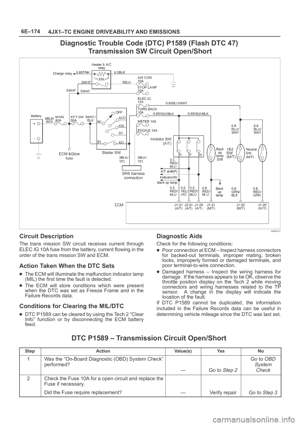
Diagnostic Trouble Code (DTC) P1589 (Flash DTC 47)
Transmission SW Circuit Open/Short
060RW131
Circuit Description
The trans mission SW circuit receives current through
ELEC IG 10A fuse from the battery, current flowing in the
order of the trans mission SW and ECM.
Action Taken When the DTC Sets
The ECM will illuminate the malfunction indicator lamp
(MIL) the first time the fault is detected.
The ECM will store conditions which were present
when the DTC was set as Freeze Frame and in the
Failure Records data.
Conditions for Clearing the MIL/DTC
DTC P1589 can be cleared by using the Tech 2 “Clear
Info” function or by disconnecting the ECM battery
feed.
Diagnostic Aids
Check for the following conditions:
Poor connection at ECM – Inspect harness connectors
for backed-out terminals, improper mating, broken
locks, improperly formed or damaged terminals, and
poor terminal-to-wire connection.
Damaged harness – Inspect the wiring harness for
damage. If the harness appears to be OK, observe the
throttle position display on the Tech 2 while moving
connectors and wiring harnesses related to the TP
sensor. A change in the display will indicate the
location of the fault.
If DTC P1589 cannot be duplicated, the information
included in the Failure Records data can be useful in
determining vehicle mileage since the DTC was last set.
DTC P1589 – Transmission Circuit Open/Short
StepActionVa l u e ( s )Ye sNo
1Was the “On-Board Diagnostic (OBD) System Check”
performed?
—Go to Step 2
Go to OBD
System
Check
2Check the Fuse 10A for a open circuit and replace the
Fuse if necessary.
Did the Fuse require replacement?
—Verify repairGo to Step 3
Page 2071 of 6000
6E–178
4JX1–TC ENGINE DRIVEABILITY AND EMISSIONS
Hard Start Symptom
StepNo Ye s Va l u e ( s ) Action
121. Check the battery voltage.
2. If a problem is found, repair as necessary.
Was a problem found?
—Verify repairGo to Step 13
131. Check for the following engine mechanical
problems (Refer to
Engine Mechanical):
Low compression
Leaking cylinder head gaskets
Worn or incorrect camshaft
Camshaft drive belt slipped or stripped
2. If a problem is found, repair as necessary.
Was a problem found?
—Verify repairGo to Step 14
141. Review all diagnostic procedures within this table.
2. If all procedures have been completed and no
malfunctions have been found, review/inspect the
following:
Visual/physical inspection
Tech–2 data
Freeze Frame data/Failure Records buffer
All electrical connections within a suspected
circuit and/or system.
3. If a problem is found, repair as necessary.
Was a problem found?
—Verify repair
Contact
Te c h n i c a l
Assistance
Page 2084 of 6000

6E–191 4JX1–TC ENGINE DRIVEABILITY AND EMISSIONS
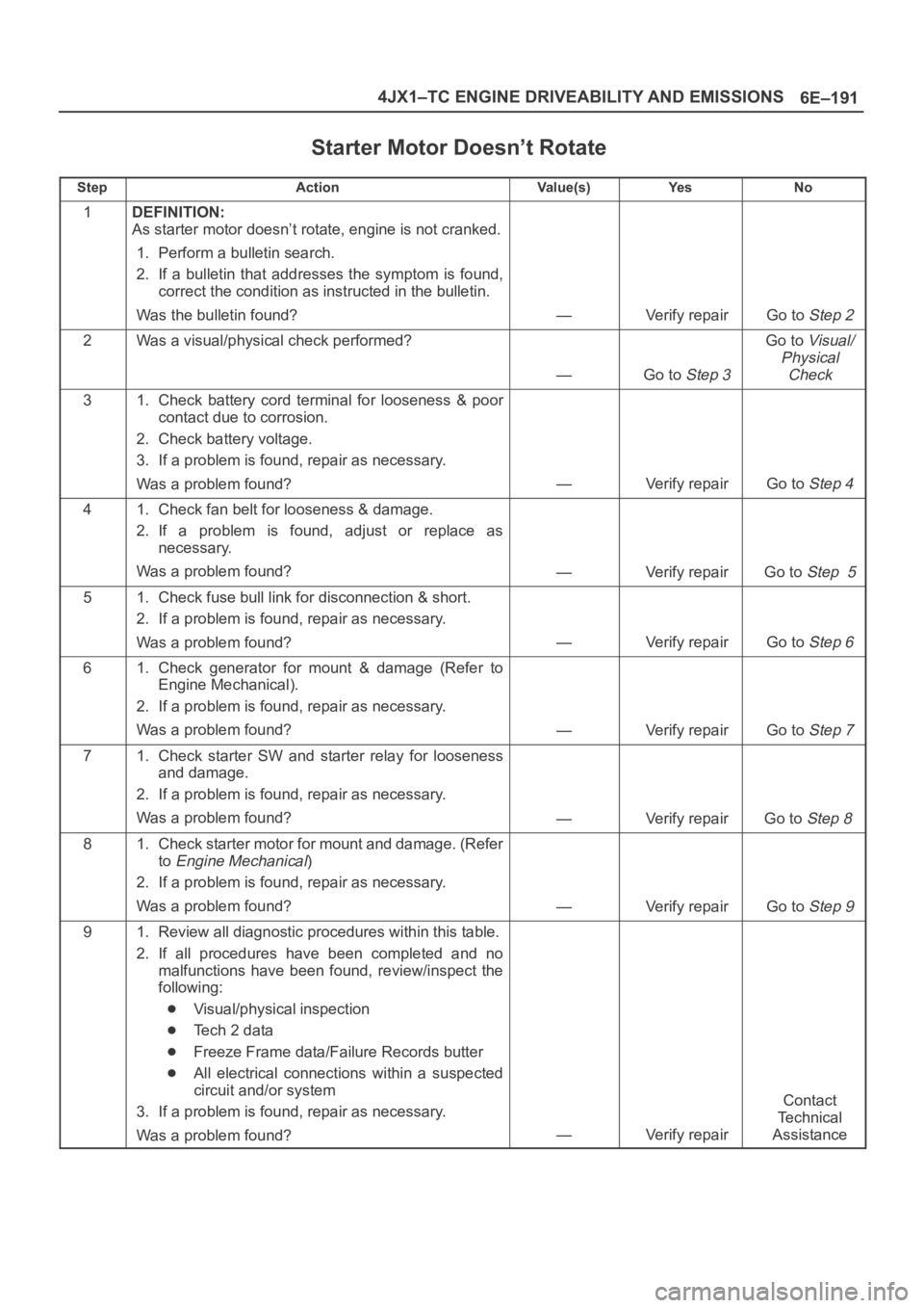
Starter Motor Doesn’t Rotate
StepActionVa l u e ( s )Ye sNo
1DEFINITION:
As starter motor doesn’t rotate, engine is not cranked.
1. Perform a bulletin search.
2. If a bulletin that addresses the symptom is found,
correct the condition as instructed in the bulletin.
Was the bulletin found?
—Verify repairGo to Step 2
2Was a visual/physical check performed?
—Go to Step 3
Go to Visual/
Physical
Check
31. Check battery cord terminal for looseness & poor
contact due to corrosion.
2. Check battery voltage.
3. If a problem is found, repair as necessary.
Was a problem found?
—Verify repairGo to Step 4
41. Check fan belt for looseness & damage.
2. If a problem is found, adjust or replace as
necessary.
Was a problem found?
—Verify repairGo to Step 5
51. Check fuse bull link for disconnection & short.
2. If a problem is found, repair as necessary.
Was a problem found?
—Verify repairGo to Step 6
61. Check generator for mount & damage (Refer to
Engine Mechanical).
2. If a problem is found, repair as necessary.
Was a problem found?
—Verify repairGo to Step 7
71. Check starter SW and starter relay for looseness
and damage.
2. If a problem is found, repair as necessary.
Was a problem found?
—Verify repairGo to Step 8
81. Check starter motor for mount and damage. (Refer
to
Engine Mechanical)
2. If a problem is found, repair as necessary.
Was a problem found?
—Verify repairGo to Step 9
91. Review all diagnostic procedures within this table.
2. If all procedures have been completed and no
malfunctions have been found, review/inspect the
following:
Visual/physical inspection
Te c h 2 d a t a
Freeze Frame data/Failure Records butter
All electrical connections within a suspected
circuit and/or system
3. If a problem is found, repair as necessary.
Was a problem found?
—Verify repair
Contact
Te c h n i c a l
Assistance
Page 2094 of 6000
6E–201 4JX1–TC ENGINE DRIVEABILITY AND EMISSIONS
On–Vehicle Service
Camshaft Position (CMP)
Sensor
Removal Procedure
1. Disconnect the negative battery cable.
2. Disconnect the electrical connector to the CMP
sensor.
035RW071
3. Remove the CMP sensor retaining bolt from the
cylinder head cover.
035RW075
Inspection Procedure
1. Inspect the sensor O-ring for cracks or leaks.
2. Replace the O-ring if it is worn or damaged.
3. Lubricate the new O-ring with engine oil.
4. Install the lubricated O-ring.
Installation Procedure
1. Install the CMP sensor in the cylinder head cover.
2. Install the CMP sensor retaining bolt.
Tighten
Tighten the retaining bolt to 9 Nꞏm (78 lb in.).
035RW075
3. Connect the electrical connector to the CMP sensor.
035RW071
4. Connect the negative battery cable.
Page 2095 of 6000
6E–202
4JX1–TC ENGINE DRIVEABILITY AND EMISSIONS
Crankshaft Position (CKP)
Sensor
Removal Procedure
1. Disconnect the negative battery cable.
2. Remove the under cover.
035RW091
3. Disconnect the electrical connector to the CKP
sensor.
4. Remove one bolt and the CKP sensor from the left
side of the engine block.
NOTE: Use caution to avoid any hot oil that might drip
out.
035RW090
Inspection Procedure
1. Inspect the sensor O-ring for cracks or leaks.
2. Replace the O-ring if it is worn or damaged.
3. Lubricate the new O-ring with engine oil.
4. Install the lubricated O-ring.
Installation Procedure
1. Install the CKP sensor in the engine block.
2. Install the CKP sensor mounting bolt.
Tighten
Tighten the mounting bolt to 9 Nꞏm (78 lb in.).
035RW090
3. Connect the electrical connector to the CKP sensor.
4. Install the under cover.
035RW091
5. Connect the negative battery cable.
Page 2096 of 6000

6E–203 4JX1–TC ENGINE DRIVEABILITY AND EMISSIONS
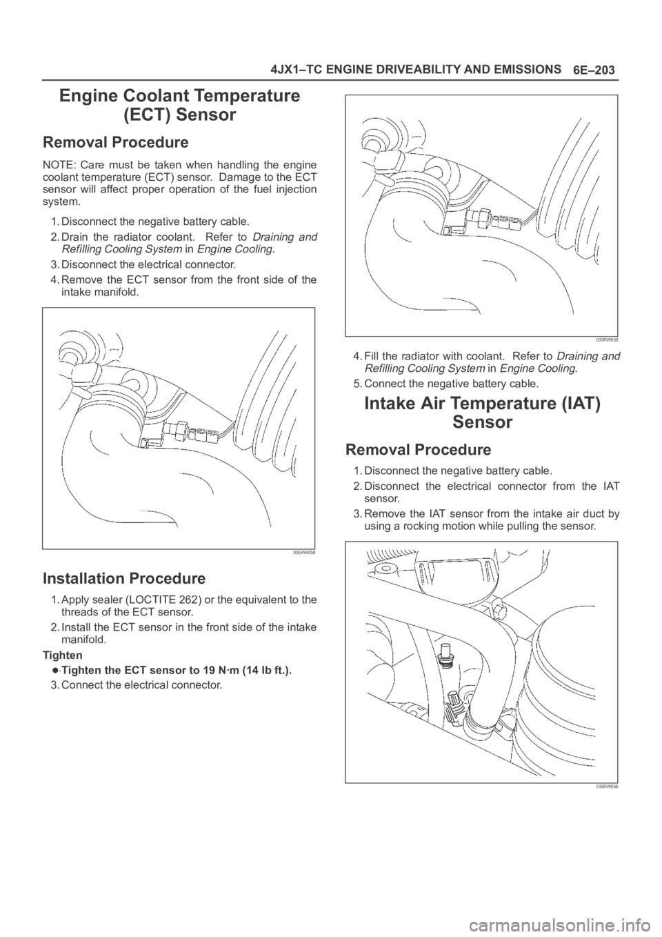
Engine Coolant Temperature
(ECT) Sensor
Removal Procedure
NOTE: Care must be taken when handling the engine
coolant temperature (ECT) sensor. Damage to the ECT
sensor will affect proper operation of the fuel injection
system.
1. Disconnect the negative battery cable.
2. Drain the radiator coolant. Refer to
Draining and
Refilling Cooling System
in Engine Cooling.
3. Disconnect the electrical connector.
4.Remove the ECT sensor from the front side of the
intake manifold.
035RW058
Installation Procedure
1. Apply sealer (LOCTITE 262) or the equivalent to the
threads of the ECT sensor.
2. Install the ECT sensor in the front side of the intake
manifold.
Tighten
Tighten the ECT sensor to 19 Nꞏm (14 lb ft.).
3. Connect the electrical connector.
035RW058
4. Fill the radiator with coolant. Refer to Draining and
Refilling Cooling System
in Engine Cooling.
5. Connect the negative battery cable.
Intake Air Temperature (IAT)
Sensor
Removal Procedure
1. Disconnect the negative battery cable.
2. Disconnect the electrical connector from the IAT
sensor.
3. Remove the IAT sensor from the intake air duct by
using a rocking motion while pulling the sensor.
035RW056
Page 2097 of 6000
6E–204
4JX1–TC ENGINE DRIVEABILITY AND EMISSIONS
Installation Procedure
1. Install the IAT sensor into the grommet in the intake
air duct.
035RW056
2. Correct the IAT electrical connector.
3. Connect the negative battery cable.
Manifold Absolute Pressure
(MAP) Sensor
Removal Procedure
1. Disconnect the negative battery cable.
2. Disconnect the EGR valve.
035RW054
3. Disconnect the MAP sensor connector from the MAP
sensor.
035RW053
4.Remove the bolts and the MAP sensor from the
intake manifold.
035RW057
Page 2098 of 6000
6E–205 4JX1–TC ENGINE DRIVEABILITY AND EMISSIONS
Installation Procedure
1. Install the MAP sensor and bolts on the intake
manifold.
Torque: 4 Nꞏm (35 lb in)
035RW057
2. Connect the MAP sensor connector.
035RW053
3. Connect the EGR valve.
035RW054
4. Connect the negative battery cable.
Oil Temperature (OT) Sensor
Removal Procedure
1. Disconnect the negative battery cable.
2. Remove the battery.
035RW095