1998 OPEL FRONTERA oil pressure
[x] Cancel search: oil pressurePage 5739 of 6000
7A–50
AUTOMATIC TRANSMISSION (4L30–E)
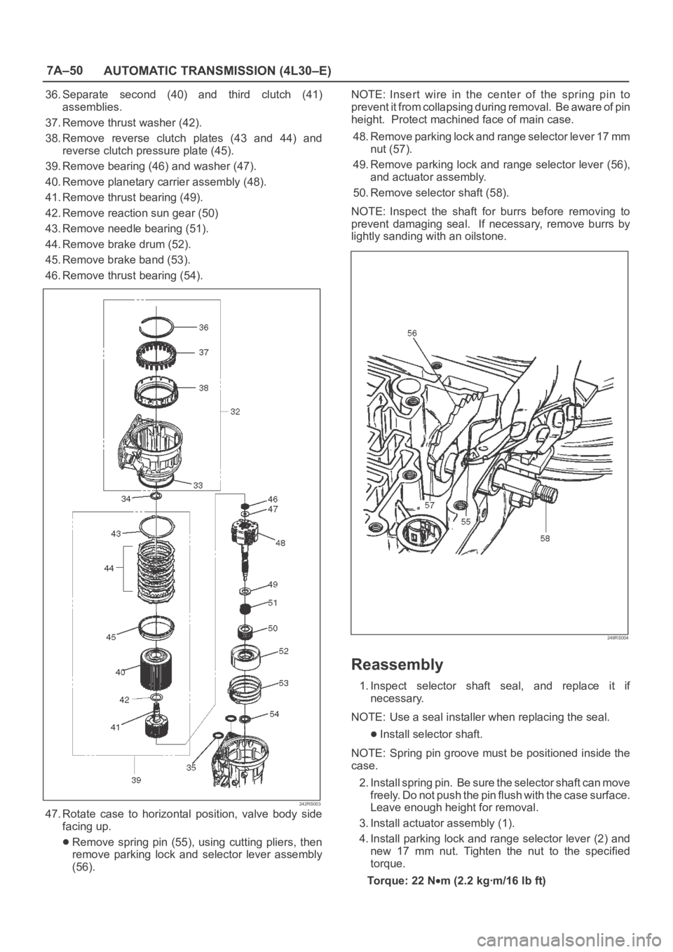
36. Separate second (40) and third clutch (41)
assemblies.
37. Remove thrust washer (42).
38. Remove reverse clutch plates (43 and 44) and
reverse clutch pressure plate (45).
39. Remove bearing (46) and washer (47).
40. Remove planetary carrier assembly (48).
41. Remove thrust bearing (49).
42. Remove reaction sun gear (50)
43. Remove needle bearing (51).
44. Remove brake drum (52).
45. Remove brake band (53).
46. Remove thrust bearing (54).
242RS003
47. Rotate case to horizontal position, valve body side
facing up.
Remove spring pin (55), using cutting pliers, then
remove parking lock and selector lever assembly
(56).NOTE: Insert wire in the center of the spring pin to
prevent it from collapsing during removal. Be aware of pin
height. Protect machined face of main case.
48. Remove parking lock and range selector lever 17 mm
nut (57).
49. Remove parking lock and range selector lever (56),
and actuator assembly.
50. Remove selector shaft (58).
NOTE: Inspect the shaft for burrs before removing to
prevent damaging seal. If necessary, remove burrs by
lightly sanding with an oilstone.
249RS004
Reassembly
1. Inspect selector shaft seal, and replace it if
necessary.
NOTE: Use a seal installer when replacing the seal.
Install selector shaft.
NOTE: Spring pin groove must be positioned inside the
case.
2. Install spring pin. Be sure the selector shaft can move
freely. Do not push the pin flush with the case surface.
Leave enough height for removal.
3. Install actuator assembly (1).
4. Install parking lock and range selector lever (2) and
new 17 mm nut. Tighten the nut to the specified
torque.
To r q u e : 2 2 N
m (2.2 kgꞏm/16 lb ft)
Page 5750 of 6000
7A–61 AUTOMATIC TRANSMISSION (4L30–E)
Oil Pump
Disassembled View
241RS014
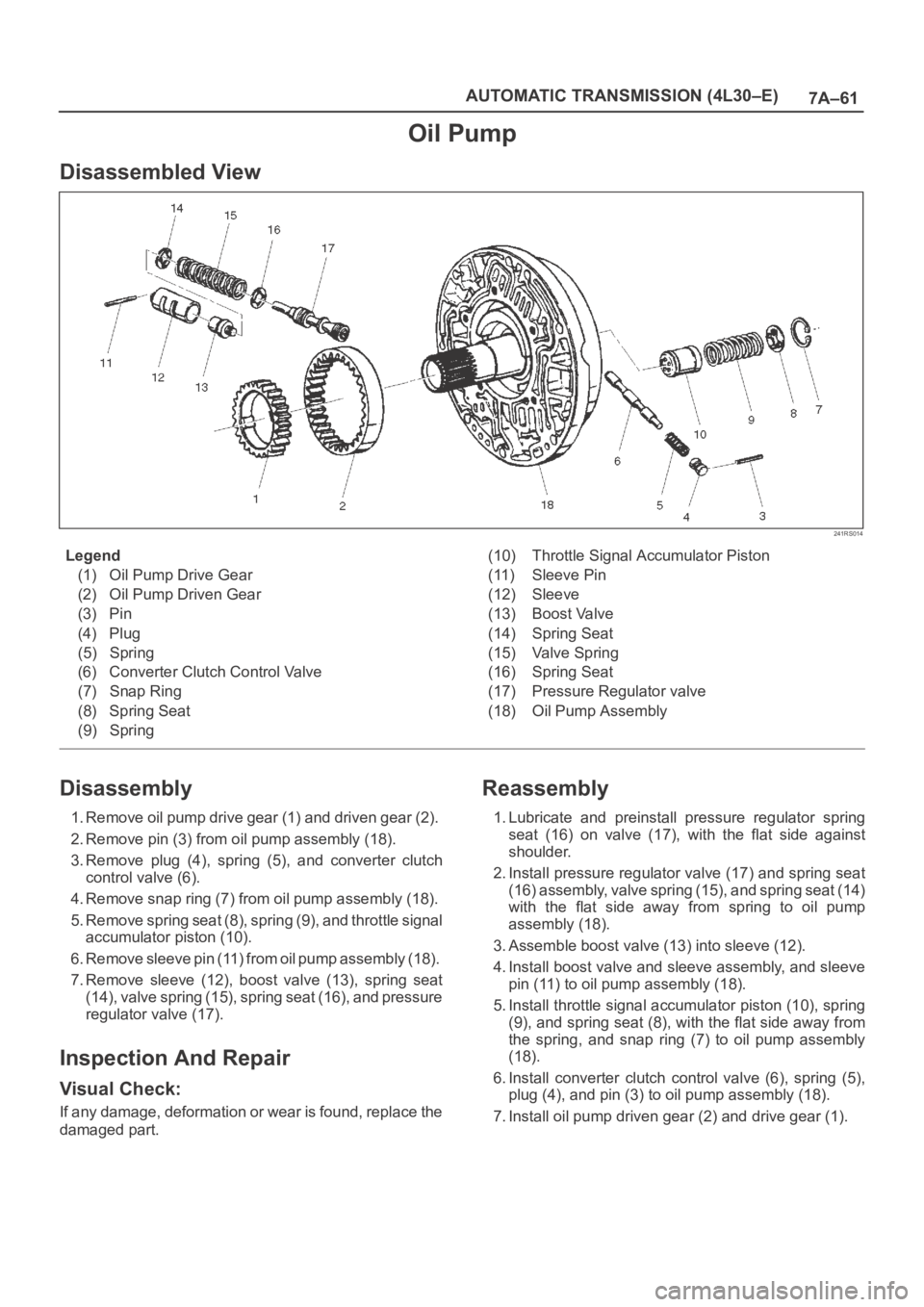
Legend
(1) Oil Pump Drive Gear
(2) Oil Pump Driven Gear
(3) Pin
(4) Plug
(5) Spring
(6) Converter Clutch Control Valve
(7) Snap Ring
(8) Spring Seat
(9) Spring(10) Throttle Signal Accumulator Piston
(11) Sleeve Pin
(12) Sleeve
(13) Boost Valve
(14) Spring Seat
(15) Valve Spring
(16) Spring Seat
(17) Pressure Regulator valve
(18) Oil Pump Assembly
Disassembly
1. Remove oil pump drive gear (1) and driven gear (2).
2. Remove pin (3) from oil pump assembly (18).
3. Remove plug (4), spring (5), and converter clutch
control valve (6).
4. Remove snap ring (7) from oil pump assembly (18).
5. Remove spring seat (8), spring (9), and throttle signal
accumulator piston (10).
6. Remove sleeve pin (11) from oil pump assembly (18).
7. Remove sleeve (12), boost valve (13), spring seat
(14), valve spring (15), spring seat (16), and pressure
regulator valve (17).
Inspection And Repair
Visual Check:
If any damage, deformation or wear is found, replace the
damaged part.
Reassembly
1. Lubricate and preinstall pressure regulator spring
seat (16) on valve (17), with the flat side against
shoulder.
2. Install pressure regulator valve (17) and spring seat
(16) assembly, valve spring (15), and spring seat (14)
with the flat side away from spring to oil pump
assembly (18).
3. Assemble boost valve (13) into sleeve (12).
4. Install boost valve and sleeve assembly, and sleeve
pin (11) to oil pump assembly (18).
5. Install throttle signal accumulator piston (10), spring
(9), and spring seat (8), with the flat side away from
the spring, and snap ring (7) to oil pump assembly
(18).
6. Install converter clutch control valve (6), spring (5),
plug (4), and pin (3) to oil pump assembly (18).
7. Install oil pump driven gear (2) and drive gear (1).
Page 5752 of 6000
7A–63 AUTOMATIC TRANSMISSION (4L30–E)
10. Remove retainer (13), 2–3 shift valve (14), and spring
(15).
11. Remove spring pin (16), plug (17), spring (18), and
low pressure control valve (19).
12. Remove spring pin (20), plug (21), and band control
screen assembly (22).
13. Remove spring pin (23), plug (24), 1–2 accumulator
valve (25), and 1–2 accumulator control valve (26).
14. Remove check ball (27) from valve body (28).
Inspection And Repair
Inspect for the following, and replace any damaged or
worn parts:
1. Damage or wear to each valve.
2. Damage in oil passeges.
3. Cracks or damage to valve body.
4. Valve operations.
5. Spring fatigue.
Reassembly
1. Install 1–2 accumulator control valve (26), 1–2
accumulator valve (25), plug (24), and spring pin (23).
2. Install band control screen assembly (22), plug (21),
and spring pin (20).
3. Install low pressure control valve (19), spring (18),
plug (17), and spring pin (16).
4. Install spring (15), 2–3 shift valve (14), retainer (13),
solenoid B (12), and spring pin (11).
5. Install spring (10), 1–2/3–4 shift valve (9), retainer (8),
solenoid A (7), and spring pin (6).
6. Install waved washer (5), band control solenoid (3),
and pin (4).
7. Install manual valve (2).
8. Install check ball (27) to valve body (28).9. Install gasket (valve body/transfer plate) and transfer
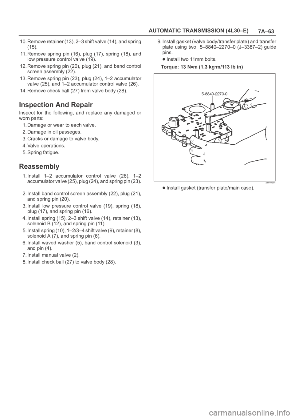
plate using two 5–8840–2270–0 (J–3387–2) guide
pins.
Install two 11mm bolts.
To r q u e : 1 3 N
m (1.3 kgꞏm/113 lb in)
244RW004
Install gasket (transfer plate/main case).
Page 5774 of 6000
7A–85 AUTOMATIC TRANSMISSION (4L30–E)
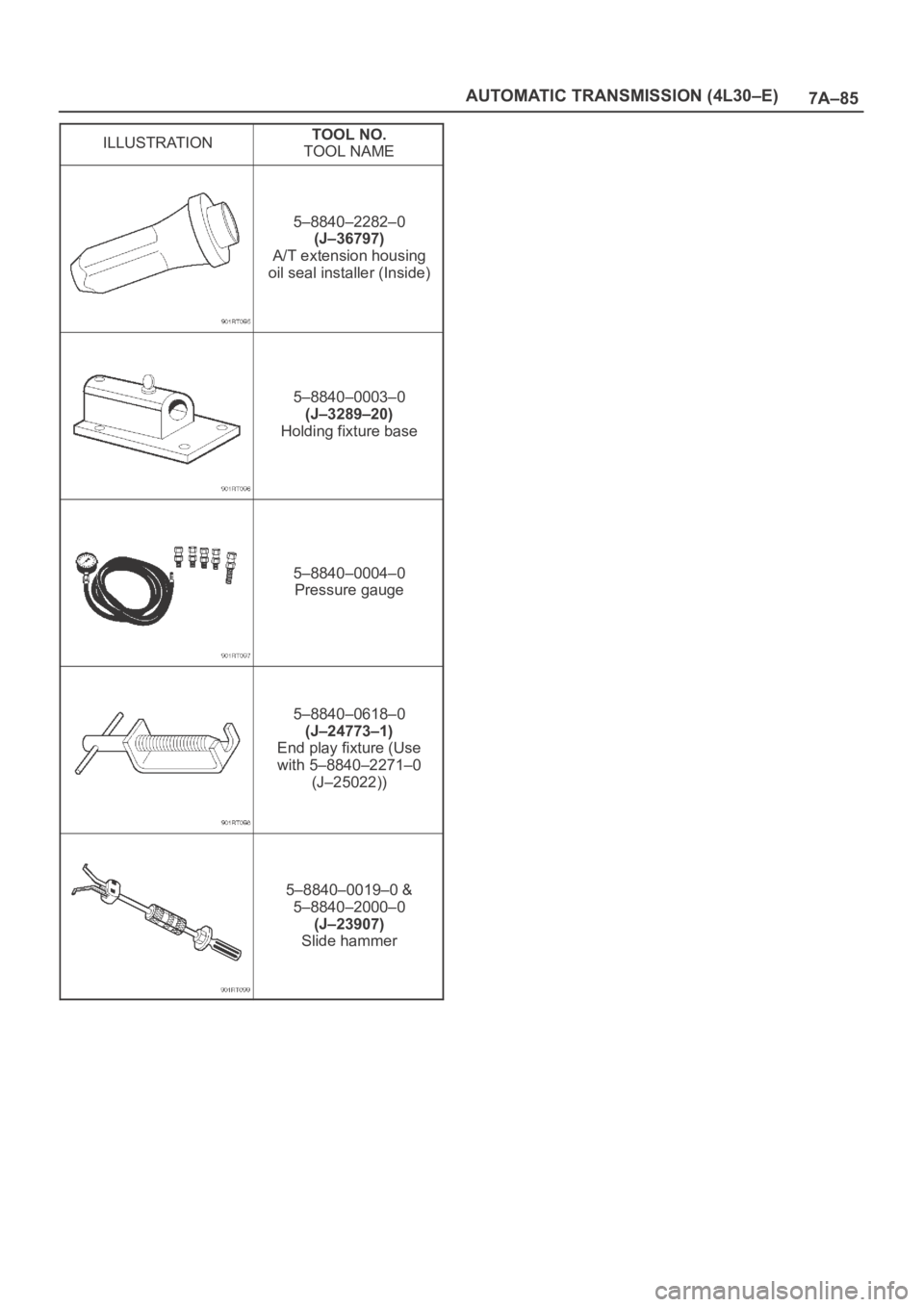
ILLUSTRATIONTOOL NO.
TOOL NAME
5–8840–2282–0
(J–36797)
A/T extension housing
oil seal installer (Inside)
5–8840–0003–0
(J–3289–20)
Holding fixture base
5–8840–0004–0
Pressure gauge
5–8840–0618–0
(J–24773–1)
End play fixture (Use
with 5–8840–2271–0
(J–25022))
5–8840–0019–0 &
5–8840–2000–0
(J–23907)
Slide hammer
Page 5776 of 6000
7A–87 AUTOMATIC TRANSMISSION (4L30–E)
(38) Seal, O–Ring
(39) Reservoir
(42) Gasket, Extension Case
(43) Extension Assembly
(44) Seal, O–Ring/Speed Sensor
(45) Sensor Assembly, Speed
(46) Screw, Speed Sensor
(50) Seal, Extension Assembly
(52) Screw, Extension/Main Case
(53) Spring, Parking Pawl Lock
(54) Pawl, Parking Lock
(55) Connector, Electrical/Main Case
(56) Actuator Assembly, Parking Lock
(57) Nut, Parking Lock Lever
(58) Link, Manual Valve
(59) Pin, Spring
(60) Lever, Parking Lock and Range Selector
(61) Shaft, Selector
(62) Seal, Selector Shaft
(63) Mode Switch Assembly
(64) Screw and Conical Washer Assembly
(65) Shield, Mode Switch
(67) Pan, Bottom/Adapter Case
(68) Gasket, Bottom Pan/Adapter Case
(69) Harness Assembly, Adapter Case
(70) Screw, Valve Body
(71) Valve Body Assembly, Adapter Case
(72) Gasket, Adapter Valve Body
(73) Plate, Adapter Valve Body/Transfer
(74) Pan, Bottom/Main Case(75) Gasket, Bottom Pan/Main Case
(76) Gasket, Oil Drain or Overfill Screw
(77) Screw, Oil Drain or Overfill
(78) Magnet, Chip Collector
(79) Filter Oil
(80) Harness Assembly, Main Case
(82) Roller and Spring Assembly, Manual Detent
(84) Valve Body Assembly, Main Case
(85) Ball, Check
(86) Gasket, Main V.B./Transfer Plate
(87) Plate, Main V.B./Transfer
(88) Gasket, Transfer/Main Case
(89) Screw, Transfer Plate on V.B.
(90) Screw, Servo Cover
(91) Cover, Servo Piston
(92) Gasket, Cover/Servo Piston
(93) Ring, Retaining Servo Piston
(94) Clip, Servo Piston
(95) Nut, Servo Screw
(96) Screw, Servo Piston
(97) Piston, Servo
(98) Seal, Ring/Servo Piston
(99) Spring, Cushion/Servo Piston
(100) Seat, Cushion Spring
(101) Sleeve, Servo Piston Adjust
(102) Rod, Apply/Servo Piston
(103) Spring, Return/Servo Piston
(104) Gasket, Adapter Case/Transfer Plate
(105) Powertrain Control Module
(106) Servo Piston Assembly
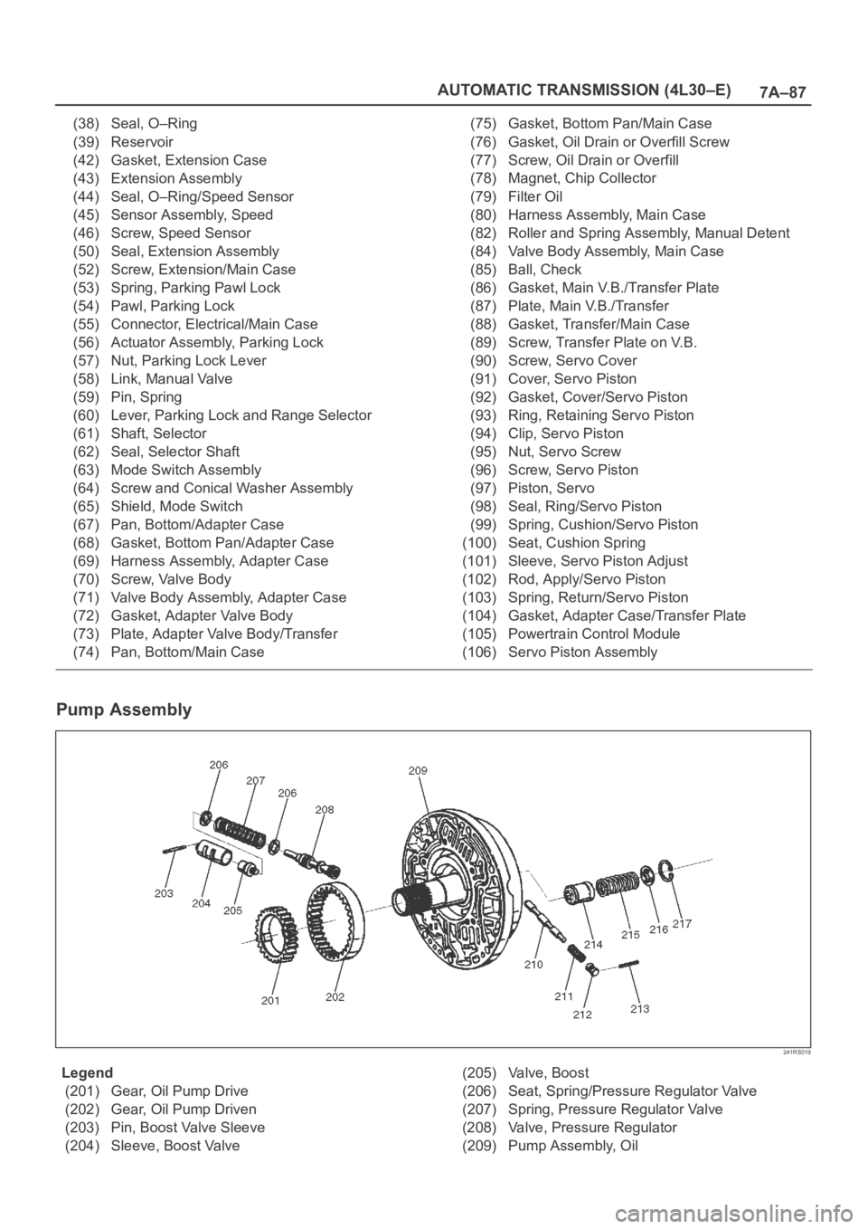
Pump Assembly
241RS019
Legend
(201) Gear, Oil Pump Drive
(202) Gear, Oil Pump Driven
(203) Pin, Boost Valve Sleeve
(204) Sleeve, Boost Valve(205) Valve, Boost
(206) Seat, Spring/Pressure Regulator Valve
(207) Spring, Pressure Regulator Valve
(208) Valve, Pressure Regulator
(209) Pump Assembly, Oil
Page 5788 of 6000

AUTOMATIC TRANSMISSION (AW30-40LE) 7A–7
CONTROL AND FUNCTIONS
Item Description
Shift and lock-up control • In D range, speed change point and Lock-up point can be changed by
setting pattern selection switch to "POWER", "NORMAL" or "WINTER"
mode.
• Gear shift position in the conditions made up of transmission shift positions
(D.2.L) combined with pattern selection switch (POWER, NORMAL, and
WINTER) can be controlled in accordance with vehicle speed and the
opening of throttle valve.
Overdrive cut control • If O/D OFF switch is set on in D range (O/D OFF lamp ON), gear shift to O/
D is not effected.
• Overdrive is released at O/D OFF switch on and high transmission oil
temperature (More than 130
C).
However, to prevent engine over revolution
•4
3 shifting at vehicle speed is less than 118 km/h.
•3
4 shifting at vehicle speed is more than 131 km/h.
Lock-up cut control • In D range, 3rd or O/D lock-up is conducted in "POWER" or "NORMAL"
mode.
• In 2, L range, lock-up is off in the whole area.
• Lock-up timing is controlled to reduce gear shift shock using kind of gear
shift (shift up, etc.) lock-up status at the time of gear shift judgement, gear
step and throttle opening after gear shift.
• Lock-up is released at brake on or high transmission oil temperature (More
than 130
C).
• Lock-up is prohibited when idling is defected by throttle position sensor.
Driving mode select control • The TCM selects a suitable driving mode from the nine kinds for the variety
driving condition.
i) Economy mode ii) Power mode iii) Winter mode iv) HOT1 mode v) HOT2
mode vi) L4 mode vii) Slope mode (Up slope 1, Up slope 2 and Down
slope mode)
• The priority of driving mode:
Economy < Power < Slope < L4 < Winter < HOT1 < HOT2
Squat control • When the TCM detects D signal on, the TCM controls 1–3–1 shift by
setting a timer, in order to improve the shift feel at N
D.
Line pressure control • The TCM output current which corresponds to throttle oil pressure to
pressure control solenoid based on throttle opening.
Indicate oil temperature warning
function• If the transmission oil temperature sensor senses that transmission oil
temperature is greater than 146
C, the TCM turn on A/T OIL TEMP
warning lamp. (The warning lamp is turned off, if oil temperature is less
than 126
C.)
L4 mode control • The TCM judges whether the transfer is engaged in high or low based on
the ratio rpm data from output speed sensor in the transmission and the
rpm data from speed meter sensor to select the shift map.
Up and down hill control • The TCM judges up and down hill, and change shift pattern based on
throttle opening and acceleration.
Correct oil temperature control • If the temperature exceeds a predetermined value, the TCM selects the
high oil temperature shift point for downshifting, thus preventing the oil
temperature from rising. (More than 130
C, D range)
Page 5790 of 6000

AUTOMATIC TRANSMISSION (AW30-40LE) 7A–9
MAJOR INPUT/OUTPUT COMPONENTS
Component Function
Input
Vehicle speed sensor (Speedometer) Detects the vehicle speed (Back-up sensor of output
revolution sensor).
Output revolution sensor (Transmission) Detects the vehicle speed.
Input revolution sensor (Transmission) Detects the input revolution (O/D direct clutch drum
revolution).
Engine revolution sensor Detects the engine revolution.
Throttle position sensor Detects the throttle opening rate.
Neutral start switch Detects the select lever position.
Pattern select switch Detects whether the driver has selected "NORMAL",
"POWER", or "WINTER" mode.
Overdrive off switch Detects whether the driver has selected O/D.
Brake lamp switch Detects whether the driver has pressed the brake pedal or
not.
Oil temperature sensor Detects the oil temperature.
Diagnostic star t switch Star ts self-diagnosis and displays a code for faulty part if
any.
Input/Output
Data link connector When connected with Tech2 or tester, can communicate
the data for function check, etc.
Output
Shift solenoid S1, S2 Selects shift point and gear position suited to the vehicle
running condition on the basis of TCM output.
Lock-up control solenoid SL Control the lock-up clutch suited to the vehicle running
condition on the basis of TCM output.
Pressure control solenoid STH Adjusts throttle pressure by energizing current of linear
pressure control solenoid to prevent the shift shock and to
obtain shift smoothly.
"CHECK TRANS" lamp When trouble has occurred to throttle position sensor,
vehicle speed sensor, or solenoid, "CHECK TRANS" lamp
is blinked to warn the driver. If also displays the trouble
code.
A/T OIL TEMP warning lamp Lights when ATF oil temperature rises. (Turned on at
greater than 146
C . Turned off at less than 126C.
Power mode lamp Informs the driver whether the vehicle is in power mode or
not.
Winter mode lamp Informs the driver whether the vehicle is in winter mode or
not.
Computer
Transmission Control Module (TCM) Based on the signal from each switch and sensors, judges
necessary shift point and lock-up operation, and send
signal to each solenoid.
Page 5794 of 6000
AUTOMATIC TRANSMISSION (AW30-40LE) 7A–13
DIAGNOSIS
BASIC TROUBLESHOOTING
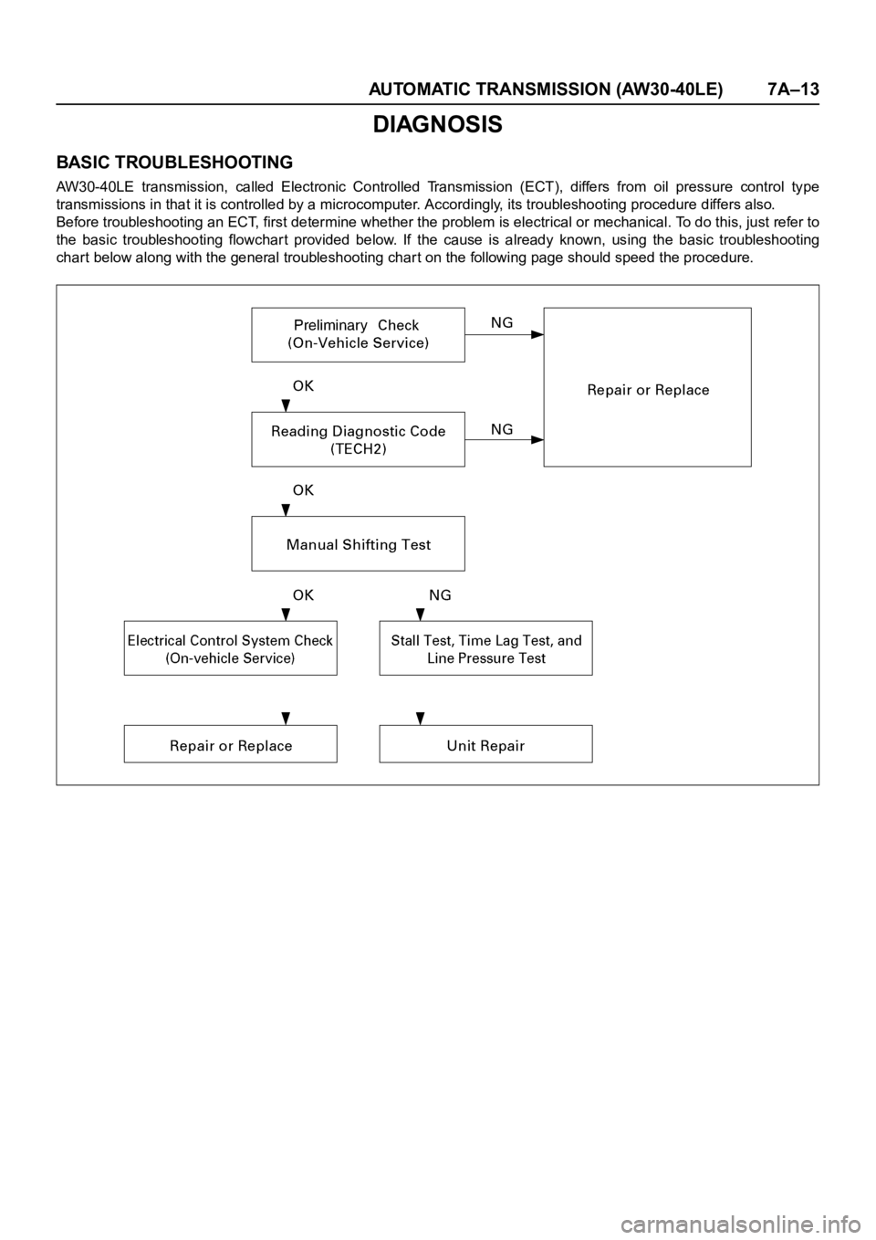
AW30-40LE transmission, called Electronic Controlled Transmission (ECT), differs from oil pressure control type
transmissions in that it is controlled by a microcomputer. Accordingly, its troubleshooting procedure differs also.
Before troubleshooting an ECT, first determine whether the problem is electrical or mechanical. To do this, just refer to
the basic troubleshooting flowchart provided below. If the cause is already known, using the basic troubleshooting
chart below along with the general troubleshooting char t on the following page should speed the procedure.