Page 1736 of 6000

ENGINE MECHANICAL 6A – 3
SERVICE INFORMATION
MAIN DATA AND SPECIFICATION
Engine type Diesel, four cycle water cooled inline
Camshaft type DOHC
Number of cylinders 4
Bore x stroke (mm) 95.4 x 104.9
Total piston displacement (cc) 2999
Compression ratio (to 1) 19.0
For Europe : 18.5
Engine weight (dry) N (kg/lb) 2492 (254/560) (A/T)
For Europe : 2422 (247/545) (A/T)
2649 (270/593) (M/T)
For Europe : 2697 (275/606) (M/T)
Engine idling speed (Reference) RPM 720
Compression pressure kpa (kg/cm
2/psi)-rpm 3040 (31/441)-200
Firing order 1–3–4–2
VALVE SYSTEM
Intake valves open at: B.T.D.C. 3°
close at: A.B.D.C. 57.6°
Exhaust valves open at: B.B.D.C. 56.5°
close at: A.T.D.C. 5°
Valve clearance (at cold) mm (in)
intake: 0.15 (0.006)
exhaust: 0.25 (0.01)
Oil filter Full flow and bypass combined type
Oil capacity (Original factory fill or rebuilt engine) 9.0 liters (7.9 US quarts)
Oil capacity (Service change)
with filter change 6.0 liters (6.3 US quarts)
without filter change 5.0 liters (5.3 US quarts)
Oil cooler Water cooled type
Inter cooler Air cooled type
Turbocharger method
Control method Wastegate control
Lubrication Pressurized control
Cooling method Coolant cooled
Crankshaft
As tufftriding (Nitrizing treatment) is applied to increase
crankshaft strength, crankpins and journals should not
be reground.
Piston Cooling
An oiling jet device for piston cooling is provided in the
lubricating oil circuit from the cylinder block oil gallery
via a check valve.
Take care not to damage any oiling jet when removing
and installing piston and connecting assembly.
Fuel Injection System
The injection system is oil rail type.
Quick On Start 4 System
QOS4 preheating system which features a quick-on
glow plug with thermometer control of the glowing time
and the afterglow time function, is applied.
Page 1743 of 6000

6A – 10 ENGINE MECHANICAL
8. Check the engine oil level and replenish to the
specified level if required.
9. Start the engine and check for oil leakage from the
main oil filter.
FUEL SYSTEM
Fuel filter
Replacement Procedure
1. Loosen the used fuel filter by turning it
counterclockwise with the filter wrench.
Filter Wrench : 5-8840-0203-0
2. Clean the filter cover fitting faces.
This will allow the new fuel filter to seat properly.
3. Apply a light coat of engine oil to the O-ring.
4. Turn the fuel filter until the sealing face comes in
contact with the O-ring.
5. Turn the fuel filter with a filter wrench 2/3 of a turn
until sealed.
Filter Wrench: 5-8840-0203-0Legend
(1) Priming pump
6. Operate the priming pump until the air is discharged
completely from fuel system.
NOTE: The use of an Isuzu genuine fuel filter is
strongly recommended.
COOLING SYSTEM
Coolant Level
Check the coolant level and replenish the radiator
reserve tank as necessary.
If the coolant level falls below the “‘MIN” line, carefully
check the cooling system for leakage. Then add
enough coolant to bring the level up to the “MAX” line.
NOTE: Do not overfill the reserve tank.
012RW112
012RW078
1
012RW111
012RW080
Page 1744 of 6000

ENGINE MECHANICAL 6A – 11
Remove the radiator filler cap only when absolutely
necessary.
Always check the coolant level when the engine is cold.
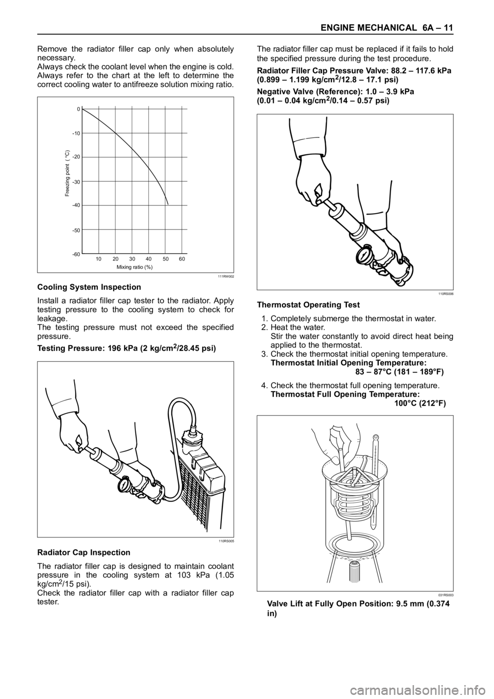
Always refer to the chart at the left to determine the
correct cooling water to antifreeze solution mixing ratio.
Cooling System Inspection
Install a radiator filler cap tester to the radiator. Apply
testing pressure to the cooling system to check for
leakage.
The testing pressure must not exceed the specified
pressure.
Testing Pressure: 196 kPa (2 kg/cm
2/28.45 psi)
Radiator Cap Inspection
The radiator filler cap is designed to maintain coolant
pressure in the cooling system at 103 kPa (1.05
kg/cm
2/15 psi).
Check the radiator filler cap with a radiator filler cap
tester.The radiator filler cap must be replaced if it fails to hold
the specified pressure during the test procedure.
Radiator Filler Cap Pressure Valve: 88.2 – 117.6 kPa
(0.899 – 1.199 kg/cm
2/12.8 – 17.1 psi)
Negative Valve (Reference): 1.0 – 3.9 kPa
(0.01 – 0.04 kg/cm
2/0.14 – 0.57 psi)
Thermostat Operating Test
1. Completely submerge the thermostat in water.
2. Heat the water.
Stir the water constantly to avoid direct heat being
applied to the thermostat.
3. Check the thermostat initial opening temperature.
Thermostat Initial Opening Temperature:
83 – 87°C (181 – 189°F)
4. Check the thermostat full opening temperature.
Thermostat Full Opening Temperature:
100°C (212°F)
Valve Lift at Fully Open Position: 9.5 mm (0.374
in)0
-10
-20
-30
-40
-50
-60
10 20 30
Mixing ratio (%)
Freezing point (
C)
40 50 60
111RW002
110RS005
110RS006
031RS003
Page 1745 of 6000
6A – 12 ENGINE MECHANICAL
Drive Belt Adjustment
Check the drive belt tension
Depress the drive belt mid-portion with a 98 N (10 kg/
22 lb) force.
Drive Belt Deflection: 10 mm (0.39 in)
Check the drive belt for cracking and other damage.
Legend
(1) Crankshaft pulley
(2) Generator pulley
(3) Cooling fan pulley
(4) A/C compressor pulley
(5) Belt tensioner pulley
Cooling Fan Pulley Drive Belt
Fan belt tension is adjusted by moving the generator.
Depress the drive belt mid-portion with a 98 N (10 kg/
22 lb) force.Legend
(1) Crankshaft pulley
(2) Generator pulley
(3) Cooling fan pulley
Compressor Pulley Drive Belt
Move the tensioner pulley as required to adjust the
compressor drive belt tension.
Depress the drive belt mid-portion with a 98 N (10 kg/
22 lb) force.
Legend
(1) Crankshaft pulley
(2) Generator pulley
(3) Cooling fan pulley
(4) A/C compressor pulley
(5) Belt tensioner pulley
5
3
24
1
012RW110
3
2
1
012RW084
5
3
24
1
012RW110
Page 1752 of 6000
ENGINE MECHANICAL 6A – 19
Injector
Nꞏm (kgꞏm/lbꞏft)
E06R200022
With
spacer type
Without
spacer type
20Nꞏm(2.0kgꞏm/14 Ib ft)
7Nꞏm(0.7kgꞏm/61 Ib in)
Recheck tightening torque
after tighten the oil rail
Apply engine oil on the
thread of stud bolts
20Nꞏm(2.0kgꞏm/14 Ib ft)
Tighten 30Nꞏm(3.1kgꞏm/22 Ib ft)
Then loosen it again tighten with
24Nꞏm(2.4kgꞏm/17 Ib ft)
Apply engine oil
both side
Page 1796 of 6000

ENGINE MECHANICAL 6A – 63
Valve Guide Replacement
1. Using the special tool, drive out the valve guide
from the combustion chamber side.
Valve guide replacer: 9-8523-1212-0
2. Apply engine oil to the outside of the valve guide.
Using the special tool, drive in a new valve guide
from cylinder head upper face side, and check the
valve guide height.
Valve guide replacer: 9-8523-1212-0
Height: 8.0 mm (0.315 in)
NOTE: If the valve guide has been removed, both the
valve and the valve guide must be replaced as a set.
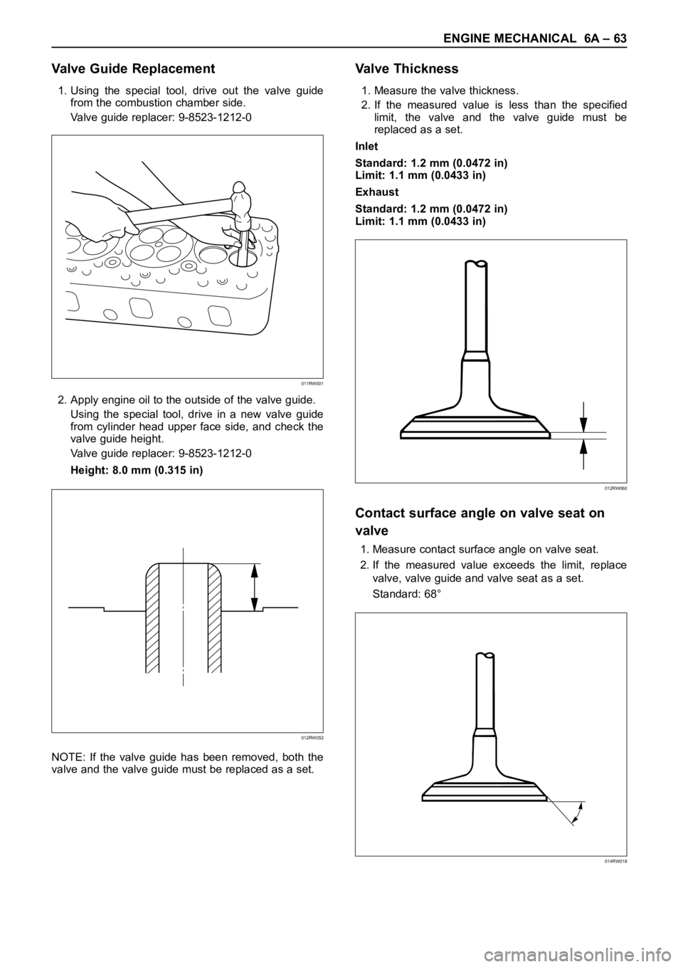
Va l v e T h i c k n e s s
1. Measure the valve thickness.
2. If the measured value is less than the specified
limit, the valve and the valve guide must be
replaced as a set.
Inlet
Standard: 1.2 mm (0.0472 in)
Limit: 1.1 mm (0.0433 in)
Exhaust
Standard: 1.2 mm (0.0472 in)
Limit: 1.1 mm (0.0433 in)
Contact surface angle on valve seat on
valve
1. Measure contact surface angle on valve seat.
2. If the measured value exceeds the limit, replace
valve, valve guide and valve seat as a set.
Standard: 68°
011RW001
012RW052
012RW060
014RW018
Page 1797 of 6000

6A – 64 ENGINE MECHANICAL
Valve Depression
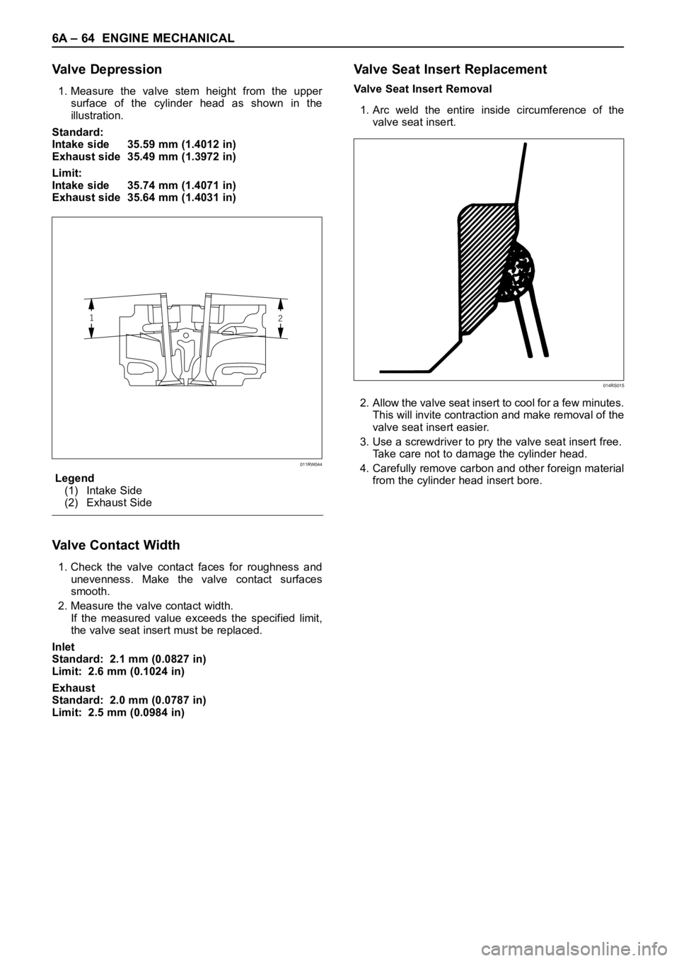
1. Measure the valve stem height from the upper
surface of the cylinder head as shown in the
illustration.
Standard:
Intake side 35.59 mm (1.4012 in)
Exhaust side 35.49 mm (1.3972 in)
Limit:
Intake side 35.74 mm (1.4071 in)
Exhaust side 35.64 mm (1.4031 in)
Legend
(1) Intake Side
(2) Exhaust Side
Valve Contact Width
1. Check the valve contact faces for roughness and
unevenness. Make the valve contact surfaces
smooth.
2. Measure the valve contact width.
If the measured value exceeds the specified limit,
the valve seat insert must be replaced.
Inlet
Standard: 2.1 mm (0.0827 in)
Limit: 2.6 mm (0.1024 in)
Exhaust
Standard: 2.0 mm (0.0787 in)
Limit: 2.5 mm (0.0984 in)
Valve Seat Insert Replacement
Valve Seat Insert Removal
1. Arc weld the entire inside circumference of the
valve seat insert.
2. Allow the valve seat insert to cool for a few minutes.
This will invite contraction and make removal of the
valve seat insert easier.
3. Use a screwdriver to pry the valve seat insert free.
Take care not to damage the cylinder head.
4. Carefully remove carbon and other foreign material
from the cylinder head insert bore.
12
011RW044
014RS015
Page 1798 of 6000

ENGINE MECHANICAL 6A – 65
Valve Seat Insert Installation
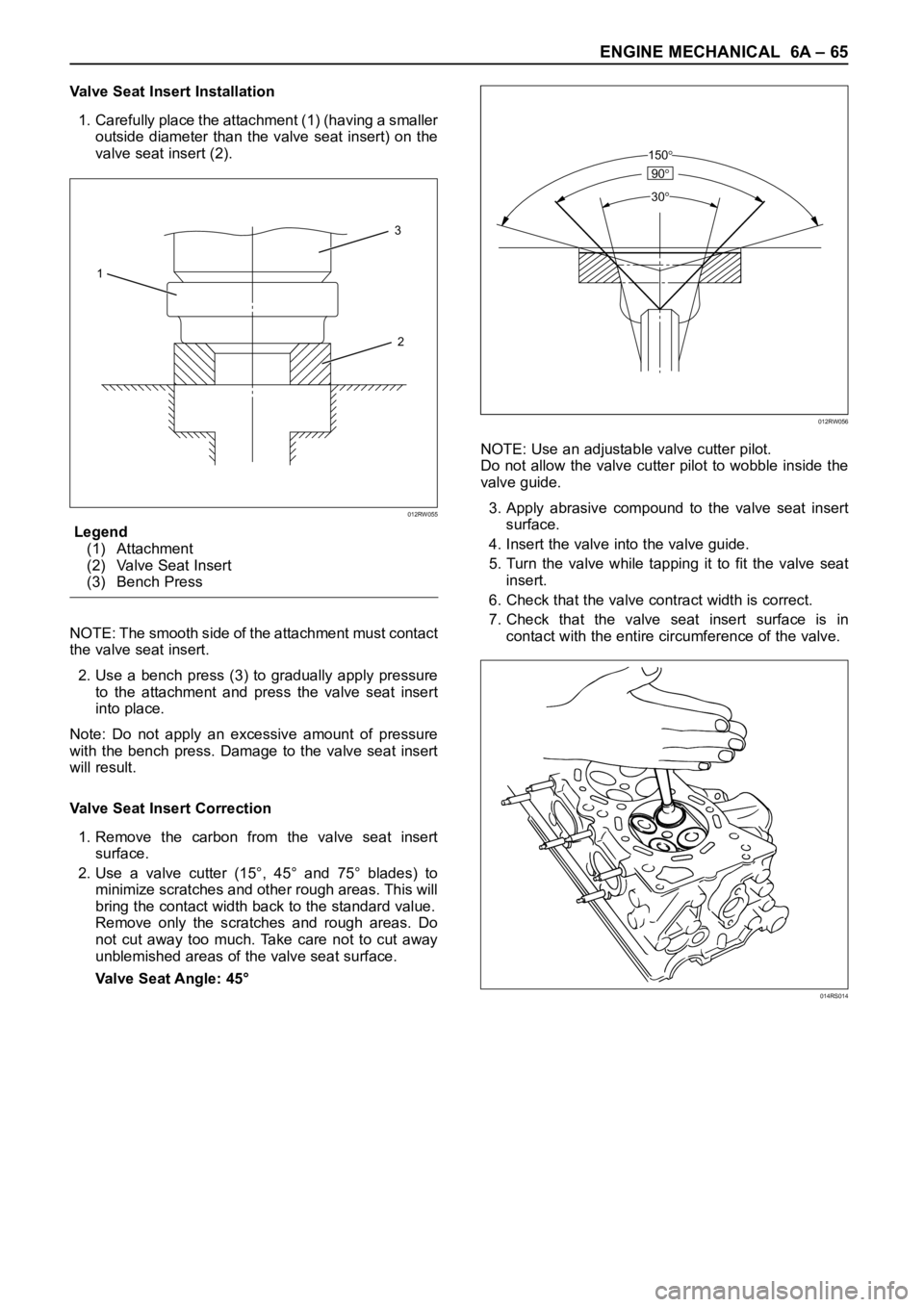
1. Carefully place the attachment (1) (having a smaller
outside diameter than the valve seat insert) on the
valve seat insert (2).
Legend
(1) Attachment
(2) Valve Seat Insert
(3) Bench Press
NOTE: The smooth side of the attachment must contact
the valve seat insert.
2. Use a bench press (3) to gradually apply pressure
to the attachment and press the valve seat insert
into place.
Note: Do not apply an excessive amount of pressure
with the bench press. Damage to the valve seat insert
will result.
Valve Seat Insert Correction
1. Remove the carbon from the valve seat insert
surface.
2. Use a valve cutter (15°, 45° and 75° blades) to
minimize scratches and other rough areas. This will
bring the contact width back to the standard value.
Remove only the scratches and rough areas. Do
not cut away too much. Take care not to cut away
unblemished areas of the valve seat surface.
Valve Seat Angle: 45°NOTE: Use an adjustable valve cutter pilot.
Do not allow the valve cutter pilot to wobble inside the
valve guide.
3. Apply abrasive compound to the valve seat insert
surface.
4. Insert the valve into the valve guide.
5. Turn the valve while tapping it to fit the valve seat
insert.
6. Check that the valve contract width is correct.
7. Check that the valve seat insert surface is in
contact with the entire circumference of the valve.
3
2 1
012RW055
150
90
30
012RW056
014RS014