1998 OPEL FRONTERA hood open
[x] Cancel search: hood openPage 3245 of 6000
8F–50BODY STRUCTURE
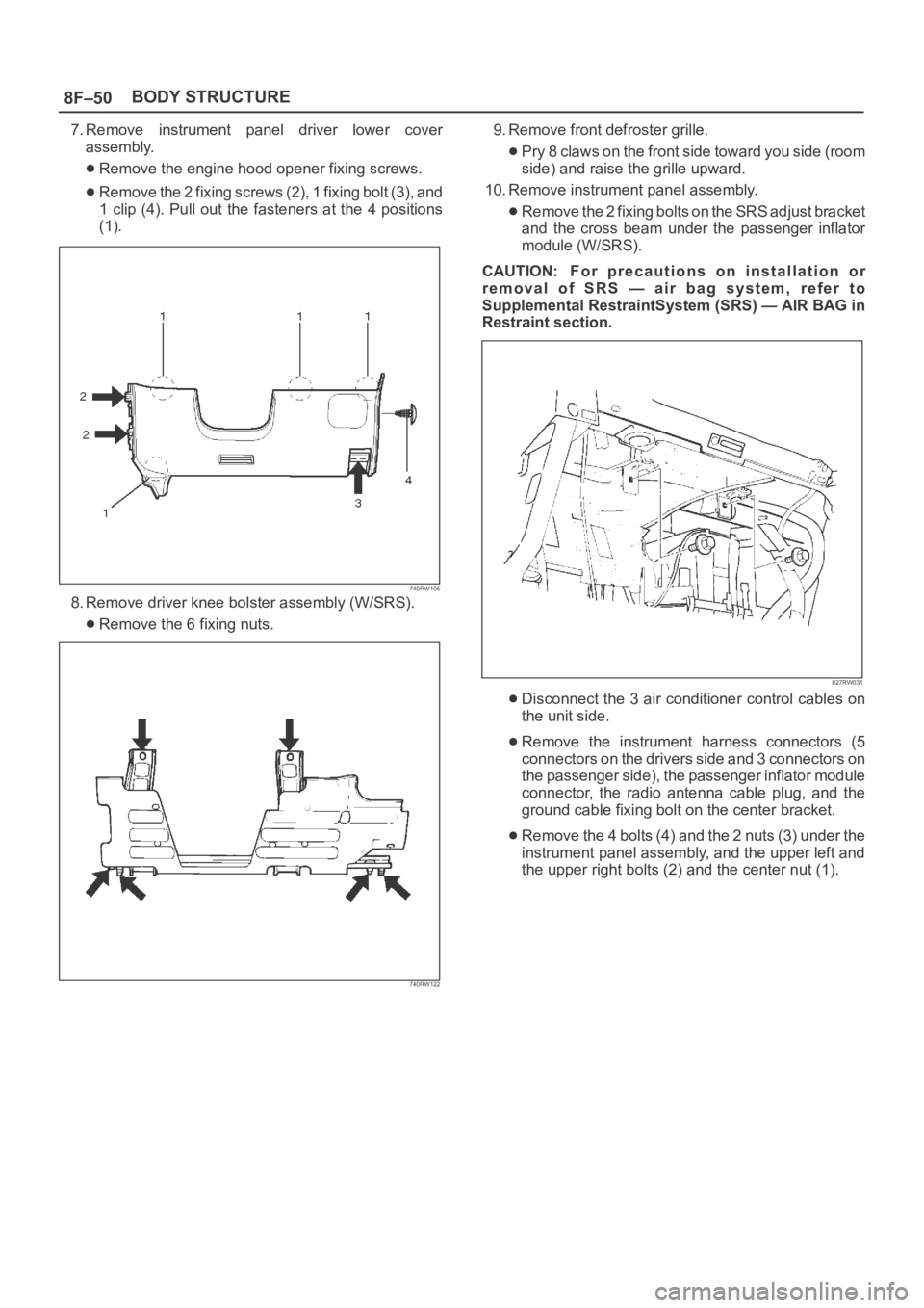
7. Remove instrument panel driver lower cover
assembly.
Remove the engine hood opener fixing screws.
Remove the 2 fixing screws (2), 1 fixing bolt (3), and
1 clip (4). Pull out the fasteners at the 4 positions
(1).
740RW105
8. Remove driver knee bolster assembly (W/SRS).
Remove the 6 fixing nuts.
740RW122
9. Remove front defroster grille.
Pry 8 claws on the front side toward you side (room
side) and raise the grille upward.
10. Remove instrument panel assembly.
Remove the 2 fixing bolts on the SRS adjust bracket
and the cross beam under the passenger inflator
module (W/SRS).
CAUTION: For precautions on installation or
removal of SRS — air bag system, refer to
Supplemental RestraintSystem (SRS) — AIR BAG in
Restraint section.
827RW031
Disconnect the 3 air conditioner control cables on
the unit side.
Remove the instrument harness connectors (5
connectors on the drivers side and 3 connectors on
the passenger side), the passenger inflator module
connector, the radio antenna cable plug, and the
ground cable fixing bolt on the center bracket.
Remove the 4 bolts (4) and the 2 nuts (3) under the
instrument panel assembly, and the upper left and
the upper right bolts (2) and the center nut (1).
Page 3248 of 6000
8F–53 BODY STRUCTURE
Installation
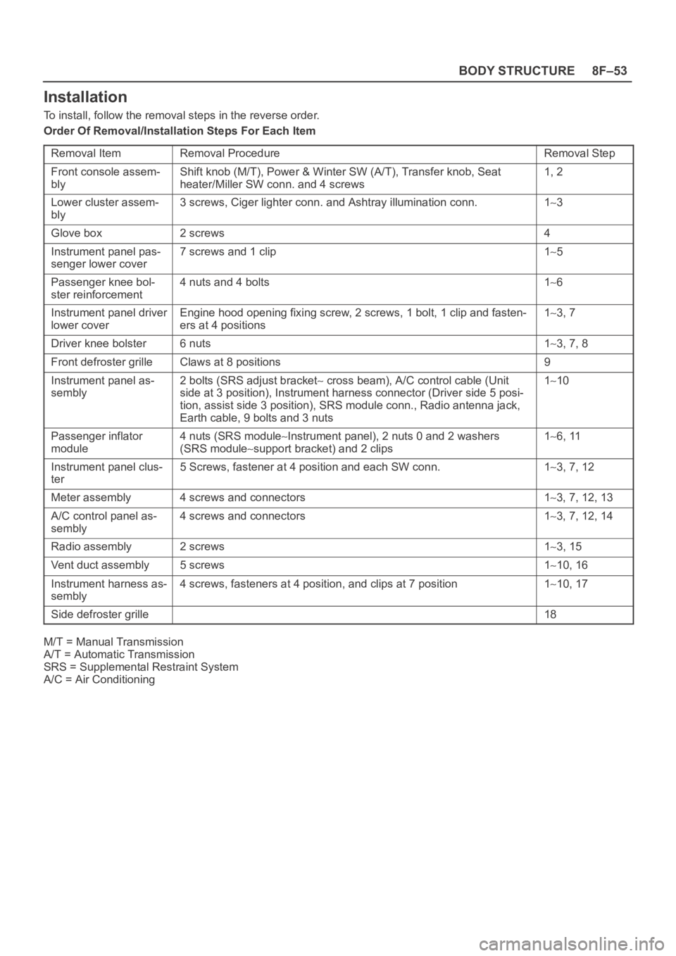
To install, follow the removal steps in the reverse order.
Order Of Removal/Installation Steps For Each Item
Removal Item
Removal ProcedureRemoval Step
Front console assem-
blyShift knob (M/T), Power & Winter SW (A/T), Transfer knob, Seat
heater/Miller SW conn. and 4 screws1, 2
Lower cluster assem-
bly3 screws, Ciger lighter conn. and Ashtray illumination conn.13
Glove box2 screws4
Instrument panel pas-
senger lower cover7 screws and 1 clip15
Passenger knee bol-
ster reinforcement4 nuts and 4 bolts16
Instrument panel driver
lower coverEngine hood opening fixing screw, 2 screws, 1 bolt, 1 clip and fasten-
ers at 4 positions13, 7
Driver knee bolster6 nuts13, 7, 8
Front defroster grilleClaws at 8 positions9
Instrument panel as-
sembly2 bolts (SRS adjust bracket cross beam), A/C control cable (Unit
side at 3 position), Instrument harness connector (Driver side 5 posi-
tion, assist side 3 position), SRS module conn., Radio antenna jack,
Earth cable, 9 bolts and 3 nuts110
Passenger inflator
module4 nuts (SRS moduleInstrument panel), 2 nuts 0 and 2 washers
(SRS module
support bracket) and 2 clips
16, 11
Instrument panel clus-
ter5 Screws, fastener at 4 position and each SW conn.13, 7, 12
Meter assembly4 screws and connectors13, 7, 12, 13
A/C control panel as-
sembly4 screws and connectors13, 7, 12, 14
Radio assembly2 screws13, 15
Vent duct assembly5 screws110, 16
Instrument harness as-
sembly4 screws, fasteners at 4 position, and clips at 7 position110, 17
Side defroster grille18
M/T = Manual Transmission
A/T = Automatic Transmission
SRS = Supplemental Restraint System
A/C = Air Conditioning
Page 3477 of 6000
SUPPLEMENTAL RESTRAINT SYSTEM 9J–40
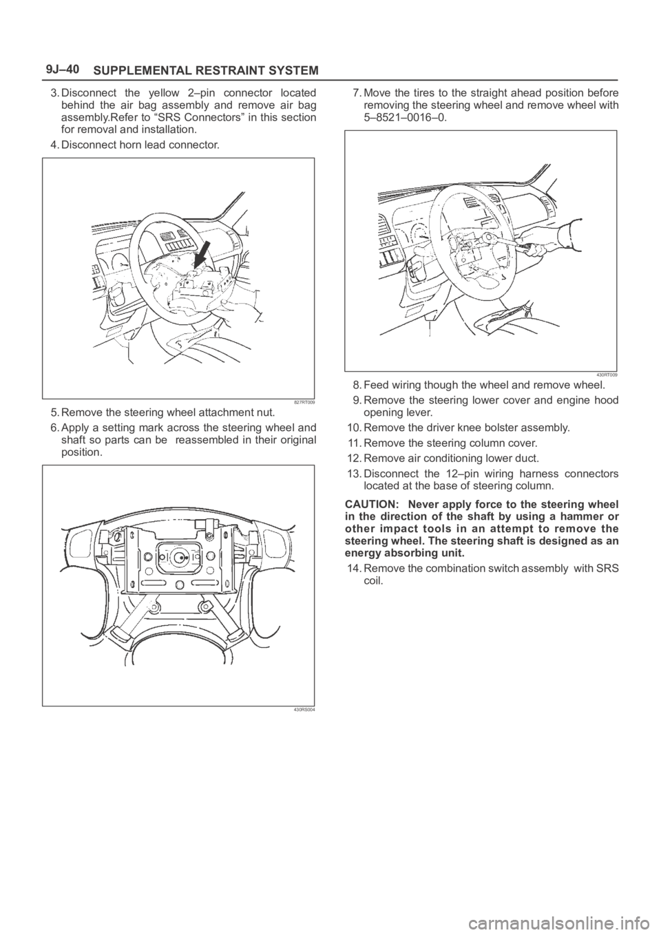
3. Disconnect the yellow 2–pin connector located
behind the air bag assembly and remove air bag
assembly.Refer to “SRS Connectors” in this section
for removal and installation.
4. Disconnect horn lead connector.
827RT009
5. Remove the steering wheel attachment nut.
6. Apply a setting mark across the steering wheel and
shaft so parts can be reassembled in their original
position.
430RS004
7. Move the tires to the straight ahead position before
removing the steering wheel and remove wheel with
5–8521–0016–0.
430RT009
8. Feed wiring though the wheel and remove wheel.
9. Remove the steering lower cover and engine hood
opening lever.
10. Remove the driver knee bolster assembly.
11. Remove the steering column cover.
12. Remove air conditioning lower duct.
13. Disconnect the 12–pin wiring harness connectors
located at the base of steering column.
CAUTION: Never apply force to the steering wheel
in the direction of the shaft by using a hammer or
other impact tools in an attempt to remove the
steering wheel. The steering shaft is designed as an
energy absorbing unit.
14. Remove the combination switch assembly with SRS
coil.
Page 3478 of 6000
SUPPLEMENTAL RESTRAINT SYSTEM9J–41
Installation
1. Install the combination switch assembly with SRS
coil.
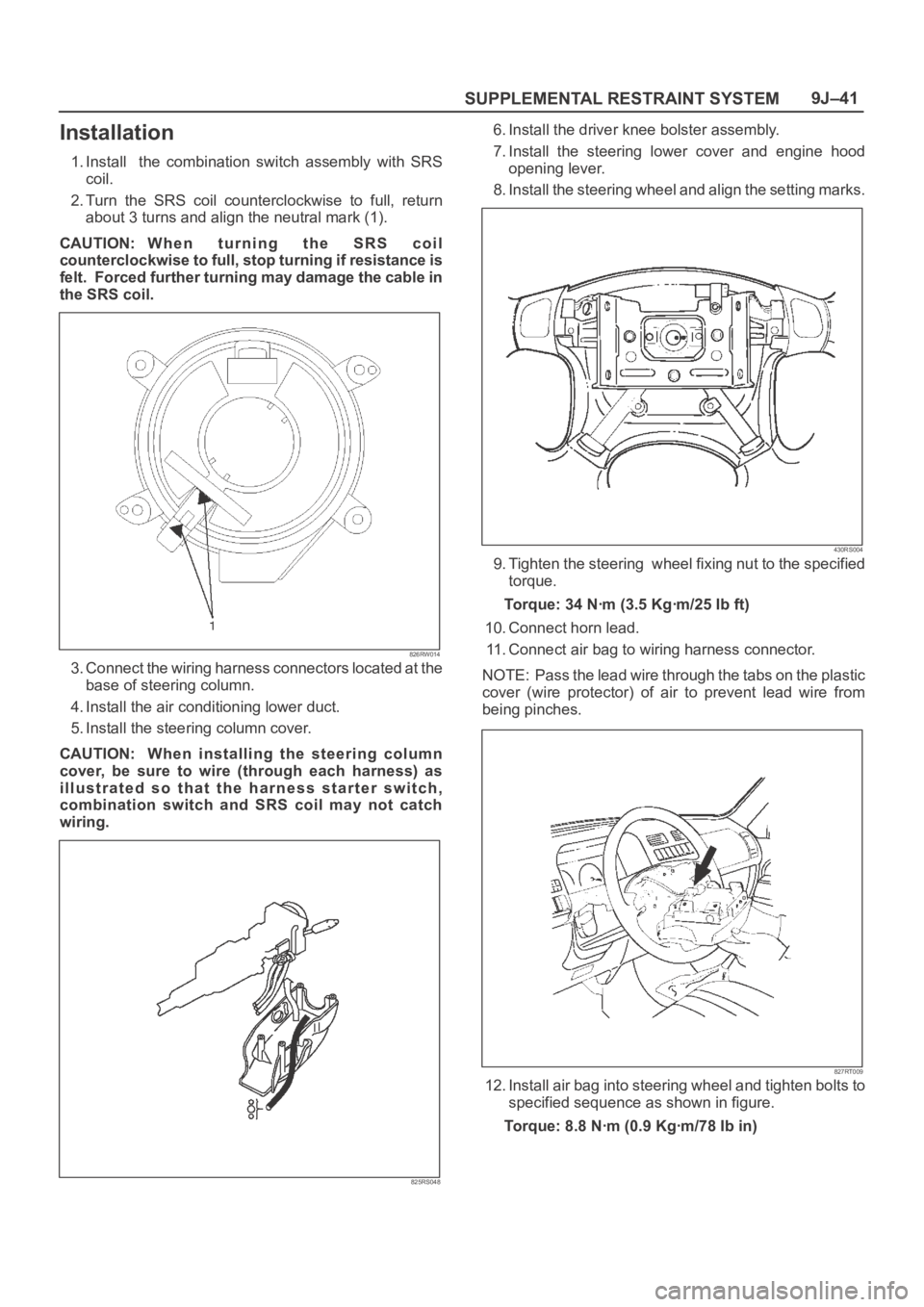
2. Turn the SRS coil counterclockwise to full, return
about 3 turns and align the neutral mark (1).
CAUTION: W h e n t u r n i n g t h e S R S c o i l
counterclockwise to full, stop turning if resistance is
felt. Forced further turning may damage the cable in
the SRS coil.
826RW014
3. Connect the wiring harness connectors located at the
base of steering column.
4. Install the air conditioning lower duct.
5. Install the steering column cover.
CAUTION: When installing the steering column
cover, be sure to wire (through each harness) as
illustrated so that the harness starter switch,
combination switch and SRS coil may not catch
wiring.
825RS048
6. Install the driver knee bolster assembly.
7. Install the steering lower cover and engine hood
opening lever.
8. Install the steering wheel and align the setting marks.
430RS004
9. Tighten the steering wheel fixing nut to the specified
torque.
Torque: 34 Nꞏm (3.5 Kgꞏm/25 Ib ft)
10. Connect horn lead.
11. Connect air bag to wiring harness connector.
NOTE: Pass the lead wire through the tabs on the plastic
cover (wire protector) of air to prevent lead wire from
being pinches.
827RT009
12. Install air bag into steering wheel and tighten bolts to
specified sequence as shown in figure.
Torque: 8.8 Nꞏm (0.9 Kgꞏm/78 Ib in)
Page 3482 of 6000
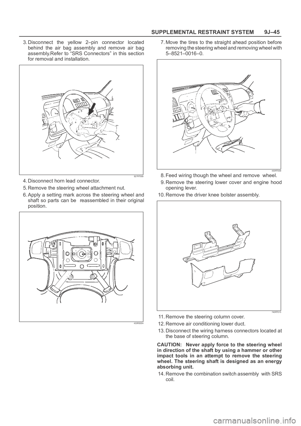
SUPPLEMENTAL RESTRAINT SYSTEM9J–45
3. Disconnect the yellow 2–pin connector located
behind the air bag assembly and remove air bag
assembly.Refer to “SRS Connectors” in this section
for removal and installation.
827RT009
4. Disconnect horn lead connector.
5. Remove the steering wheel attachment nut.
6. Apply a setting mark across the steering wheel and
shaft so parts can be reassembled in their original
position.
430RS004
7. Move the tires to the straight ahead position before
removing the steering wheel and removing wheel with
5–8521–0016–0.
430RT009
8. Feed wiring though the wheel and remove wheel.
9. Remove the steering lower cover and engine hood
opening lever.
10. Remove the driver knee bolster assembly.
740RT015
11. Remove the steering column cover.
12. Remove air conditioning lower duct.
13. Disconnect the wiring harness connectors located at
the base of steering column.
CAUTION: Never apply force to the steering wheel
in direction of the shaft by using a hammer or other
impact tools in an attempt to remove the steering
wheel. The steering shaft is designed as an energy
absorbing unit.
14. Remove the combination switch assembly with SRS
coil.
Page 3485 of 6000
SUPPLEMENTAL RESTRAINT SYSTEM 9J–48
Passenger Air Bag Assembly
Service Precautions
WARNING: SAFETY PRECAUTIONS MUST BE
FOLLOWED WHEN HANDLING A DEPLOYED AIR
BAG ASSEMBLY. AFTER DEPLOYMENT, THE AIR
BAG ASSEMBLY SURFACE MAY CONTAIN A SMALL
AMOUNT OF SODIUM HYDROXIDE, A BY–PRODUCT
OF THE DEPLOYMENT REACTION, THAT IS
IRRITATING TO THE SKIN AND EYES. MOST OF THE
POWER ON THE AIR BAG ASSEMBLY IS
HARMLESS. AS A PRECAUTION, WEAR GLOVES
AND SAFETY GLASSES WHEN HANDLING A
DEPLOYED AIR BAG ASSEMBLY, AND WASH YOUR
HANDS WITH MILD SOAP AND WATER
AFTERWARDS.
WARNING: WHEN CARRYING A LIVE AIR BAG
ASSEMBLY, MAKE SURE THE BAG AND TRIM
COVER ARE POINTED AWAY FROM YOU. NEVER
CARRY AIR BAG ASSEMBLY BY THE WIRES OR
CONNECTOR ON THE UNDERSIDE OF MODULE. IN
THE CASE OF AN ACCIDENTAL DEPLOYMENT, THE
BAG WILL THEN DEPLOY WITH MINIMAL CHANCE
OF INJURY. WHEN PLACING ALIVE AIR BAG
ASSEMBLY ON A BENCH OR OTHER SURFACE,
ALWAYS FACE BAG AND RIM COVER UP, AWAY
FROM THE SURFACE. NEVER REST A STEERING
COLUMN ASSEMBLY ON THE STEERING WHEEL
WITH THE AIR BAG ASSEMBLY FACE DOWN AND
COLUMN VERTICAL. THIS IS NECESSARY SO THAT
A FREE SPACE IS PROVIDED TO ALLOW THE AIR
BAG ASSEMBLY TO EXPAND IN THE UNLIKELY
EVENT OF ACCIDENTAL DEPLOYMENT.
OTHERWISE, PERSONAL INJURY COULD RESULT.
NOTE: IN THE EVENT DEPLOYMENT HAS
OCCURRED, INSPECT COIL ASSEMBLY WIRE FOR
ANY SIGNS OF SCORCHING, MELTING OR ANY
OTHER DAMAGE DUE TO EXCESSIVE HEAT. IF THE
COIL HAS BEEN DAMAGED, REPLACE IT.
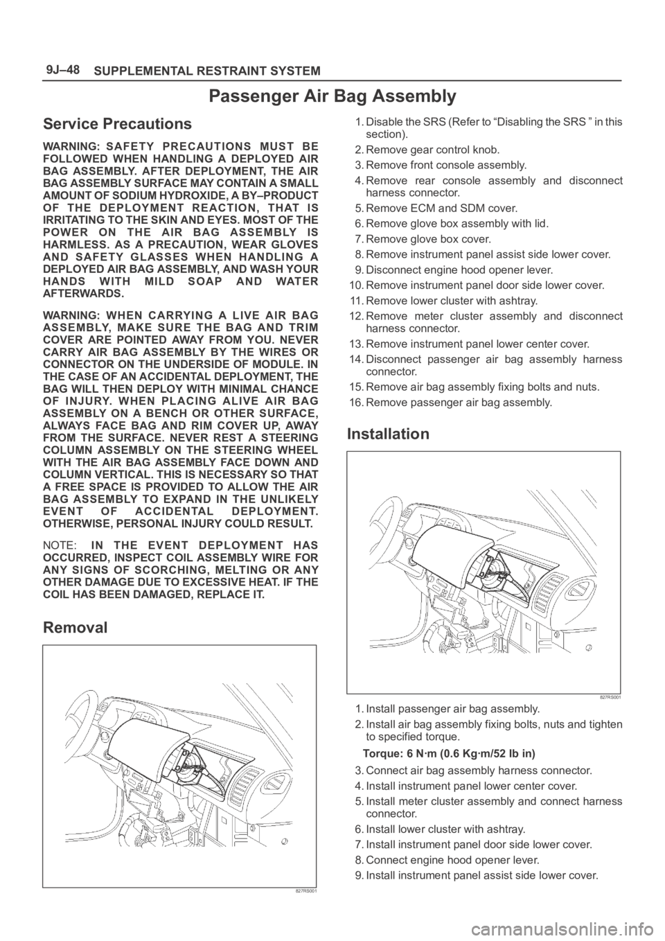
Removal
827RS001
1. Disable the SRS (Refer to “Disabling the SRS ” in this
section).
2. Remove gear control knob.
3. Remove front console assembly.
4. Remove rear console assembly and disconnect
harness connector.
5. Remove ECM and SDM cover.
6. Remove glove box assembly with lid.
7. Remove glove box cover.
8. Remove instrument panel assist side lower cover.
9. Disconnect engine hood opener lever.
10. Remove instrument panel door side lower cover.
11. Remove lower cluster with ashtray.
12. Remove meter cluster assembly and disconnect
harness connector.
13. Remove instrument panel lower center cover.
14. Disconnect passenger air bag assembly harness
connector.
15. Remove air bag assembly fixing bolts and nuts.
16. Remove passenger air bag assembly.
Installation
827RS001
1. Install passenger air bag assembly.
2. Install air bag assembly fixing bolts, nuts and tighten
to specified torque.
Torque: 6 Nꞏm (0.6 Kgꞏm/52 Ib in)
3. Connect air bag assembly harness connector.
4. Install instrument panel lower center cover.
5. Install meter cluster assembly and connect harness
connector.
6. Install lower cluster with ashtray.
7. Install instrument panel door side lower cover.
8. Connect engine hood opener lever.
9. Install instrument panel assist side lower cover.
Page 3784 of 6000

1. Perform oil return operation.
2. Discharge and recover the refrigerant and remove
the compressor.
3. Drain the compressor oil and measure the extracted
oil.
4. Check the compressor oil for contamination.
5. Adjust the oil level as required.
6. Evacuate, charge and perform the oil return
operation.
7. Check the system operation.
Contamination of Compressor Oil
Unlike engine oil, no cleaning agent is added to the
compressor oil. Even if the compressor runs for a long
period of time (approximately one season), the oil never
becomes contaminated as long as there is nothing
wrong with the compressor or its method of use.
Inspect the extracted oil for any of the following
conditions:
The capacity of the oil has increased.
The oil has changed to red.
Foreign substances, metal powder, etc., are present
in the oil.
If any of these conditions exists, the compressor
oil is contaminated. Whenever contaminated
compressor oil is discovered, the receiver/drier
must be replaced.
Oil Return Operation
There is close affinity between the oil and the
refrigerant. During normal operation, part of the oil
recirculates with the refrigerant in the system. When
checking the amount of oil in the system, or replacing
any component of the system, the compressor must be
run in advance for oil return operation. The procedure
is as follows:
1. Open all the doors and the engine hood.
2. Start the engine and air conditioning switch to "ON"
and set the fan control knob at its highest position.
3. Run the compressor for more than 20 minutes
between 800 and 1,000 rpm in order to operate the
system.
4. Stop the engine.
Replacement of Component Parts
When replacing the system component parts, supply
the following amount of oil to the component parts to be
installed.
Compressor Leak Testing (External and
Internal)
Bench-Check Procedure
1. Install test plate J-39893 on rear head of compressor.
2. Using Refrigerant Recovery System, attach center
hose of manifold gage set on charging station to a
refrigerant drum standing in an upright drum.
3. Connect charging station high and low pressure
lines to corresponding fittings on test plate J-39893.
Suction port (low-side) of compressor has large
internal opening. Discharge port (high-side) has
smaller internal opening into compressor and
deeper recess.
4. Open low pressure control, high pressure control
and refrigerant control on charging station to allow
refrigerant vapor to flow into compressor.
5. Using a leak detector, check for leaks at pressure
relief valve, rear head switch location, compressor
front and rear head seals, center cylinder seal,
through bolt head gaskets and compressor shaft
seal. After checking, shut off low pressure control
and high-pressure control on charging station.
6. If an external leak is present, perform the necessary
corrective measures and recheck for leaks to make
certain the leak has been connected.
7. Recover the refrigerant.
8. Disconnect both hoses from the test plate J-39893.
9. Add 90 ml (3 oz.) new PAG lubricant to the
compressor assembly. Rotate the complete
compressor assembly (not the crankshaft or drive
plate hub) slowly several turns to distribute oil to all
cylinder and piston areas.
10. Install a M9
1.25 threaded nut on the compressor
crankshaft if the drive plate and clutch assembly are
not installed.
11. Using a box-end wrench or socket and handle,
rotate the compressor crankshaft or clutch drive
plate on the crankshaft several turns to insure
piston assembly to cylinder wall lubrication.
12. Using Refrigerant Recovery System, connect the
charging station high-pressure line to the test plate
J-39893 high-side connector.
13. Using Refrigerant Recovery System, connect the
charging station low-pressure line to the low
pressure port of the test plate J-39893. Oil will drain
out of the compressor suction port if the compressor
is positioned with the suction port downward. (Component parts to be (Amount of Oil)
installed)
Evaporator 50 cc (1.7 fl. oz.)
Condenser 30 cc (1.0 fl. oz.)
Receiver/dryer 30 cc (1.0 fl. oz.)
Refrigerant line (one 10 cc (0.3 fl. oz.)
piece)
(Amount of oil drained (Charging amount of oil
from used compressor) to new compressor)
more than 90 cc same as drained amount
(3.0 fl.oz)
less than 90 cc (3.0 fl.oz) 90 cc (3.0 fl.oz)
Page 4729 of 6000
6E–72
ENGINE DRIVEABILITY AND EMISSIONS
Te c h 2
ParameterRefer To Typical Data
Va l u e s
(2500 RPM) Typical Data
Values (IDLE) Units
Displayed Data List
HO2S Bank 2
Sen.1 (millivolts)O2 Sensor
DataMillivolts50-950 changing
quickly50-950 changing
quicklyGeneral Description and
Operation, Fuel Control
HO2S
HO2S Bank 1
Sen.1
(ready/not
ready)O2 Sensor
DataReady
Ye s / N oReady
Ye sReady
Ye sGeneral Description and
Operation, Fuel Control
HO2S; DTC: P0135
HO2S Bank 2
Sen.1
(ready/not
ready)O2 Sensor
DataReady
Ye s / N oReady
Ye sReady
Ye sGeneral Description and
Operation, Fuel Control
HO2S
HO2S Warm-Up
Time Bank 1
Sen.1O2 Sensor
DataSeconds25-4525-45General Description and
Operation, Fuel Control
HO2S
HO2S Warm-Up
Time Bank 2
Sen.1O2 Sensor
DataSeconds25-4525-45General Description and
Operation, Fuel Control
HO2S
IAT (Intake Air
Te m p )EngineDegrees C,
Degrees F0-100C,
depends on
underhood0-80C, depends
on underhoodGeneral Description and
Operation, Intake Air
Temperature (IAT) Sensor
Ignition VoltageEngineVo l t s12.8-14.112.8-14.1General Description and
Operation, Electronic
Ignition System
Inj. Pulse Bank
1EngineMillisecond
s2.0-4.02.5-4.0General Description, Fuel
Metering, Fuel Injector
Inj. Pulse Bank
2EngineMillisecond
s2.0-4.02.5-4.0General Description, Fuel
Metering, Fuel Injector
KS Noise
Channel (Knock
Sensor)EngineVo l t s0.10-0.400.50-1.75General Description and
Operation, Knock Sensor
Purpose and Operation;
DTCs: P0352, P0327
Loop StatusEngineOpen/Clos
edClosedClosedGeneral Description and
Operation, Fuel Metering
System; DTCs:
P0125-P0155
MAF (Mass Air
Flow)EngineGrams per
second2.85-6.659.5-16.5General Description and
Operation, MAF; DTCs:
P101, P0102, P0103
MAP kPa
(Manifold
Absolute
Pressure)EngineKilopascals
——
General Description and
Operation, Manifold
Absolute Pressure (MAP)
Sensor; DTCs: P0106,
P0107, P0108
MILEngineOn/OffOffOffOn-Board Diagnostic
System Check
Power
EnrichmentEngineInactive/Ac
tiveInactiveInactiveGeneral Description and
Operation, Acceleration
Mode
Spark
(Advance)EngineDegrees
Before Top
Dead
Center15-2234-44General Description and
Operation, Electronic
Ignition System