1998 OPEL FRONTERA heating
[x] Cancel search: heatingPage 1890 of 6000

ENGINE ELECTRICAL 6D – 23
QOS4 PREHEATING SYSTEM
GENERAL DESCRIPTION
QOS4 preheating system features a quick-on glow plug
with thermometer control of the glowing time and the
afterglow time function.
The system consists of the ECM, indicator lamp, ECT
sensor, vehicle speed sensor, relay and temperature
self-control type glow plugs.With the employment of the ECT sensor, the glow time
changes according to the engine coolant temperature,
thus allowing optimum starting conditions to be
obtained.
The after glow time function is controlled by ECM.
NOTE:
Refer to DTC P0380 and P0381 of 6E section.
SYSTEM DIAGRAM
+
-KEY
50A
ECM
50A
GLOW
50A
2
WHT/
RED
0.5
BLK/
BLU
ECM J1-15 3
WHT/
RED
3
RED/
BLKMAIN
80A
8BLK/RED
Glow
Relay
GLOW PLUG 4
BATTHeater & A/C
Relay
060RW132
Page 1891 of 6000

6D – 24 ENGINE ELECTRICAL
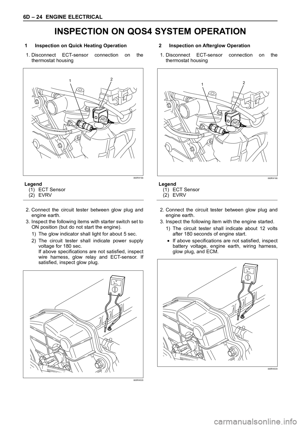
1 Inspection on Quick Heating Operation
1. Disconnect ECT-sensor connection on the
thermostat housing
Legend
(1) ECT Sensor
(2) EVRV
2. Connect the circuit tester between glow plug and
engine earth.
3. Inspect the following items with starter switch set to
ON position (but do not start the engine).
1) The glow indicator shall light for about 5 sec.
2) The circuit tester shall indicate power supply
voltage for 180 sec.
If above specifications are not satisfied, inspect
wire harness, glow relay and ECT-sensor. If
satisfied, inspect glow plug.2 Inspection on Afterglow Operation
1. Disconnect ECT-sensor connection on the
thermostat housing
Legend
(1) ECT Sensor
(2) EVRV
2. Connect the circuit tester between glow plug and
engine earth.
3. Inspect the following item with the engine started.
1) The circuit tester shall indicate about 12 volts
after 180 seconds of engine start.
If above specifications are not satisfied, inspect
battery voltage, engine earth, wiring harness,
glow plug, and ECM.
12
060RW166
065RW035
12
060RW166
065RW035
INSPECTION ON QOS4 SYSTEM OPERATION
Page 2124 of 6000

ENGINE EXHAUST 6F – 1
ENGINE EXHAUST
CONTENTS
CAUTION: Exhaust system components must have
enough clearance from the underbody to prevent
overheating of the floor pan and possible damage to the passenger compartment, insulation and trim
materials.
General Description . . . . . . . . . . . . . . . . . . 6F–2
Hangers . . . . . . . . . . . . . . . . . . . . . . . . . 6F–2
Gasket . . . . . . . . . . . . . . . . . . . . . . . . . . 6F–2
On-Vehicle Service . . . . . . . . . . . . . . . . . . . 6F–3
Front Exhaust Pipe . . . . . . . . . . . . . . . . . 6F–3Center Exhaust Pipe . . . . . . . . . . . . . . . . 6F–5
Exhaust Silencer . . . . . . . . . . . . . . . . . . . 6F–6
Rear Exhaust Pipe . . . . . . . . . . . . . . . . . 6F–7
Page 2125 of 6000

6F – 2 ENGINE EXHAUST
GENERAL DESCRIPTION
150RW070
When inspecting or replacing exhaust system
components, make sure there is adequate clearance
from all points on the underbody to prevent overheating
of the floor pan and possible damage to the passenger
compartment insulation and trim materials.
Check complete exhaust system and nearby body
areas and rear compartment lid for broken, damaged,
missing or mispositioned parts, open seams, holes
loose connections or other deterioration which could
permit exhaust fumes to seep into the rear
compartment or passenger compartment. Dust or water
in the rear compartment may be an indication of a
problem in one of these areas. Any faulty areas should
be corrected immediately.HANGERS
Various types of hangers are used to support exhaust
system(s). These include conventional rubber straps,
rubber rings, and rubber blocks.
The installation of exhaust system supports is very
important, as improperly installed supports can cause
annoying vibrations which can be difficult to diagnose.
GASKET
The gasket must be replaced whenever a new exhaust
pipe, muffler or exhaust throttle is installed.
Page 3449 of 6000

SUPPLEMENTAL RESTRAINT SYSTEM 9J–12
Deployed Air Bag Assembly (Driver Side)
“You should wear gloves and glasses. After the air bag
assembly has been deployed, the surface of the air bag
may contain solid particulate. This solid particulate
c o n s i s t s p r i m a r i l y o f b y p r oducts of the chemical reaction,
Potassium Chloride and copper metal dust. Compounds
of Potassium Borate, Strontium Chloride, Copper
Chloride, and Ammonium Chloride may be found in
amounts of about 1% (each) of the total particulate.”
Deployed Pretensioner Seat Belt.
You should wear gloves and safety glasses. After the
pretensioner seat belt has been deployed, the surface of
the pretensioner seat belt cylinder may heating up.
Air Bag Assembly and/or Pretensioner
Seat Belt Scrapping Procedure.
During the cause of vehicle’s useful life, certain situations
may arise which will necessitate the disposal of a live air
bag and/or pretensioner seat belt. (This information
covers proper procedures for disposing of a live air bag
assembly and/or pretensioner seat belt.)
Before a live air bag assembly can be dispose off, it must
be deployed.
A live air bag assembly and/or pretensioner seat belt
must not be disposed of though normal refuse channels.
WARNING: FAILURE TO FOLLOW PROPER
SUPPLEMENTAL RESTRAINT SYSTEM (SRS) AIR
BAG ASSEMBLY DISPOSAL PROCEDURES CAN
RESULT IN AIR BAG DEPLOYMENT WHICH MAY
CAUSE PERSONAL INJURY. AN UNDPLOYED AIR
BAG ASSEMBLY MUST NOT BE DISPOSED OF
THROUGH NORMAL REFUSE CHANNELS. THE
UNDEPLOYED AIR BAG ASSEMBLY CONTAINS
SUBSTANCES THAT CAN CAUSE SEVERE ILLNESS
OR PERSONAL INJURY IF THE SEALED CONTAINER
IS DAMAGED DURING DISPOSAL. DISPOSAL IN
ANY MANNER INCONSISTENT WITH PROPER
PROCEDURES MAY BE A VIOLATION OF LOCAL
LAW.
In situations which require deployment of a live air bag
assembly, deployment may be accomplished inside or
outside the vehicle. The method employed depends
upon the final disposition of the particular vehicle, as
noted in “Deployment Outside Vehicle” and “Deployment
Inside Vehicle” in this section.
Cautions About Air Bag Deployment And
Disposal
Failure to follow proper procedures could result in
erroneous air bag deployment which may cause personal
injury be sure to follow proper procedures.
1. Turn off (Lock) the ignition switch and disconnect the
minus terminal of the battery, then start the work 15 or
more sec later. (Air bag is designed to work by the
back-up power source even if the battery power
source is cut off at vehicle collision).
2. Be sure not to disassemble the air bag.
3. Do not give an impact to the air bag and bring the air
bag close to magnet. (The air bag could deploy
unexpectedly).4. Place the air bag with its trim cover up.
5. Do not let the air bag deploy directly on the floor. (The
air bag may be blown off 2
3 m (6.5 or 10 feet)).
6. Be sure to install the air bag firmly to a deployment
tool (fixing tool).
7. Set a battery 10 m (33 feet) or more away from the air
bag.
8. Before disconnecting air bag harness, ground the
worker by touching the vehicle outer panel with bare
hand.
9. When connecting or disconnecting the harness, do
not work just in front of the air bag.
10. As deployment gives rise to big sound, warn the
people around against it. Further, try to reduce the
sound by covering the steering wheel or tires, and
shut the vehicle windows in case of deployment
inside the vehicle.
11. As deployment generates smoke, select a well
ventilated place. (In case of deployment indoors,
avoid deployment just under a fire alarm, smoke
sensor, and fluorescent lamps).
12. Be careful not to inhale the smoke after deployment.
13. If part of the vehicle glass is damaged, cover the
vehicle with a car cover to prevent the glass from
braking at the time of deployment.
14. Do not touch the air bag immediately after
deployment, since it remains hot for 30 minutes.
15. Do not water the air bag immediately after
deployment.
16. Wear safety glasses and gloves throughout the work
and wash the glasses and gloves after the work.
17. Do not reuse the removed air bag for another vehicle.
(Deployment characteristic is different with vehicle
types).
Deployment Outside Vehicle (Driver Air
Bag Assembly)
Deployment outside the vehicle is proper when the
vehicle is to be returned to service. This includes, for
example, situations in which the vehicle will be returned to
useful service after a functionally or cosmetically deficient
air bag assembly is replaced. Deployment and disposal
of a malfunctioning air bag assembly is, of course, subject
to any required retention period.
For deployment of a live (undeployed) air bag assembly
outside the vehicle, the deployment procedure must be
followed exactly. Always wear safety glasses during this
deployment procedure until a deployed air bag assembly
is scrapped or until an undeployed air bag assembly is
shipped. Before performing the procedures you should
be familiar with servicing the SRS and with proper
handling of the air bag assembly. Procedures should be
read fully before they are performed.
The following procedure requires use of 5–8840–2468–0
SRS deployment harness with appropriate pigtail
adapter. Do not attempt procedure without
5–8840–2468–0 adapter.
WARNING: FAILURE TO FOLLOW PROCEDURES IN
THE ORDER LISTED MAY RESULT IN PERSONAL
INJURY. NEVER CONNECT DEPLOYMENT
Page 3561 of 6000

PAGE BACK PAGE NEXT
THIS MALUAL INCLUDES THE FOLLOWING SECTIONS:
SECTION No. CONTRNTS
1A HEATING AND VENTILATION
1B AIR CONDITIONING
1D COMPRESSOR OVERHAUL
HOME
1A
1B
1D
Page 3721 of 6000

Occurrence of a trouble
Refer to the check list for
the inspection.Locate the failed location.
Check the failed part.
Correction
Correction
Correction
Troubleshooting by the
self-diagnosis function.Reference the "Check
Procedure by Failed
Location" for the inspection.
Reference the "Check
Procedure by Failed
Location" for the inspection.Correction
Check the cooling / heating
cycles.
End OK OK OK OKNG
NG
NG
NG
NG OK
Check if the automatic
heater / air conditioner
control unit indicator LED
is turned on.Check the power supply and
circuit on the automatic
heater / air conditioner control
unit.
Troubleshooting not relying
on the self-diagnosis
function(troubleshooting
by failure type).
F01RX009
Page 4507 of 6000

6A–11
ENGINE MECHANICAL
Condition CorrectionPossible cause
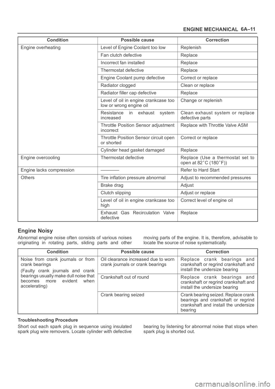
Engine overheatingLevel of Engine Coolant too lowReplenish
Fan clutch defectiveReplace
Incorrect fan installedReplace
Thermostat defectiveReplace
Engine Coolant pump defectiveCorrect or replace
Radiator cloggedClean or replace
Radiator filler cap defectiveReplace
Level of oil in engine crankcase too
low or wrong engine oilChange or replenish
Resistance in exhaust system
increasedClean exhaust system or replace
defective parts
Throttle Position Sensor adjustment
incorrectReplace with Throttle Valve ASM
Throttle Position Sensor circuit open
or shortedCorrect or replace
Cylinder head gasket damagedReplace
Engine overcoolingThermostat defectiveReplace (Use a thermostat set to
open at 82
C (180F))
Engine lacks compression————Refer to Hard Start
OthersTire inflation pressure abnormalAdjust to recommended pressures
Brake dragAdjust
Clutch slippingAdjust or replace
Level of oil in engine crankcase too
highCorrect level of engine oil
Exhaust Gas Recirculation Valve
defectiveReplace
Engine Noisy
Abnormal engine noise often consists of various noises
originating in rotating parts, sliding parts and othermoving parts of the engine. It is, therefore, advisable to
locate the source of noise systematically.
Condition
Possible causeCorrection
Noise from crank journals or from
crank bearings
(Faulty crank journals and crankOil clearance increased due to worn
crank journals or crank bearingsReplace crank bearings and
crankshaft or regrind crankshaft and
install the undersize bearing
yj
bearings usually make dull noise that
becomes more evident when
accelerating)Crankshaft out of roundReplace crank bearings and
crankshaft or regrind crankshaft and
install the undersize bearing
Crank bearing seizedCrank bearing seized. Replace crank
bearings and crankshaft or regrind
crankshaft and install the undersize
bearing
Troubleshooting Procedure
Short out each spark plug in sequence using insulated
spark plug wire removers. Locate cylinder with defectivebearing by listening for abnormal noise that stops when
spark plug is shorted out.