1998 OPEL FRONTERA fuel
[x] Cancel search: fuelPage 974 of 6000

6A–18
ENGINE MECHANICAL
Cylinder Head Cover LH
Removal
1. Disconnect battery ground cable.
2. Drain engine coolant from faucet bottom of radiator.
3. Remove engine cover from the dowels on the
common chamber.
F06RW018
4. Remove air cleaner duct assembly (3) and air cleaner
element (4).
130RW001
Legend
(1) Positive Crankcase Ventilation Hose Connector
(2) Intake Air Temperature Sensor
(3) Air Cleaner Duct Assembly
(4) Air Cleaner Element
(5) Mass Air Flow Sensor
NOTE: Disconnect the mass air flow (MAF) sensor
connector, intake air temperature (IAT) sensor connector,
and positive crankcase ventilation (PCV) hose before
hand the air cleaner duct assembly is removed.5. Disconnect following wiring connectors and bonding
cable:
Manifold Absolute Pressure (MAP) sensor
Vacuum Switching Valve (VSV) for Induction Air
Control Valve (IACV) actuator
Ignition coils for left bank
Fuel injectors for left bank
Idle air control (IAC) valve
Throttle position sensor (TPS)
Bonding cable
Others as necessitated
6. Disconnect following vacuum hoses:
Brake master VAC
Canister
VSV for IACV actuator
Duty solenoid valve
PCV
7. Disconnect radiator upper and lower hoses
8. Remove engine harness from the cylinder head
cover.
9. Remove the upper fan guide.
10. Remove cooling fan and clutch assembly.
11. Remove drive belt by pushing down the auto
tensioner using spanner as illustrated.
F06RW019
Page 977 of 6000
6A–21
ENGINE MECHANICAL
Cylinder Head Cover RH
Removal
1. Disconnect battery ground cable.
2. Remove battery from the vehicle.
3. Drain engine coolant from faucet bottom of radiator.
4. Remove engine cover from the dowels on the
common chamber.
F06RW018
5. Remove air cleaner duct assembly (3) and air cleaner
element (4).
130RW001
Legend
(1) Positive Crankcase Ventilation Hose Connector
(2) Intake Air Temperature Sensor
(3) Air Cleaner Duct Assembly
(4) Air Cleaner Element
(5) Mass Air Flow Sensor
NOTE: Disconnect the mass air flow (MAF) sensor
connector, intake air temperature (IAT) sensor connector,
and positive crankcase ventilation (PCV) hose before
hand the air cleaner duct assembly is removed.
6. Disconnect following wiring connectors and bonding
cable:
Exhaust Gas Recirculation (EGR) valve
Fuel injectors for right bank
Ignition coils for right bank
Bonding cable
Othres as necessitated
7. Disconnect radiator upper and lower hoses.
8. Remove engine harness from the cylinder head
cover.
9. Remove the upper fan guide.
10. Remove cooling fan and clutch assembly.
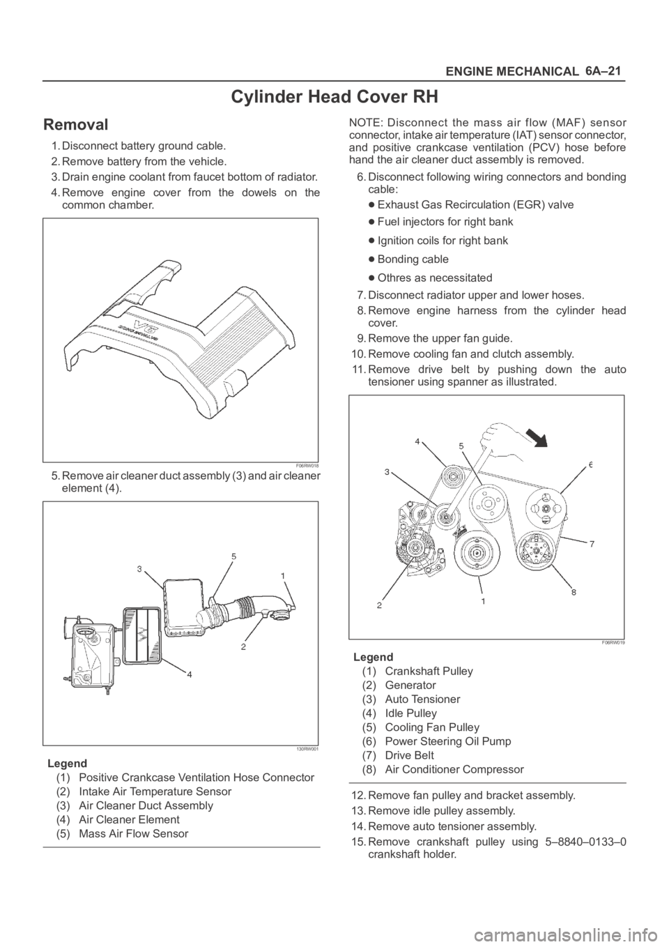
11. Remove drive belt by pushing down the auto
tensioner using spanner as illustrated.
F06RW019
Legend
(1) Crankshaft Pulley
(2) Generator
(3) Auto Tensioner
(4) Idle Pulley
(5) Cooling Fan Pulley
(6) Power Steering Oil Pump
(7) Drive Belt
(8) Air Conditioner Compressor
12. Remove fan pulley and bracket assembly.
13. Remove idle pulley assembly.
14. Remove auto tensioner assembly.
15. Remove crankshaft pulley using 5–8840–0133–0
crankshaft holder.
Page 980 of 6000
6A–24
ENGINE MECHANICAL
Common Chamber
Removal
1. Disconnect battery ground cable.
2. Remove air cleaner duct assembly.
130RW001
Legend
(1) Positive Crankcase Ventilation Hose Connector
(2) Intake Air Temperature Sensor
(3) Air Cleaner Duct Assembly
(4) Air Cleaner Element
(5) Air Flow Sensor
3. Disconnect accelerator pedal cable from throttle body
and cable bracket.
4. Disconnect vacuum booster hose from common
chamber.
5. Disconnect connector from manifold absolute
pressure sensor, idle air control valve, throttle
position sensor, solenoid valve, electric vacuum
sensing valve, and EGR valve.
6. Disconnect vacuum hose on canister VSV and
positive crankcase ventilation hose, fuel rail
assembly with pressure control valve bracket.
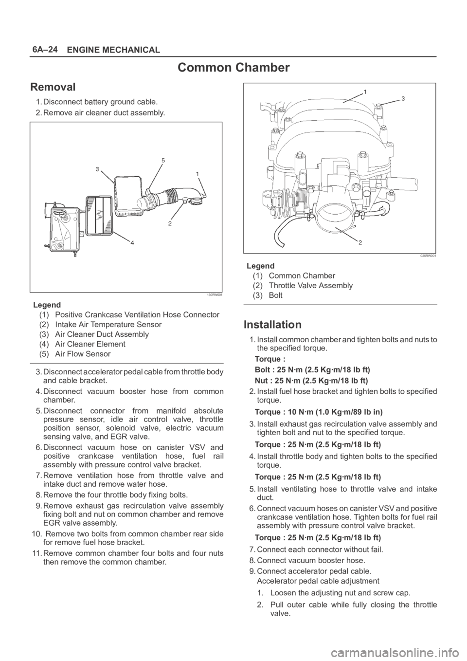
7. Remove ventilation hose from throttle valve and
intake duct and remove water hose.
8. Remove the four throttle body fixing bolts.
9. Remove exhaust gas recirculation valve assembly
fixing bolt and nut on common chamber and remove
EGR valve assembly.
10. Remove two bolts from common chamber rear side
for remove fuel hose bracket.
11. Remove common chamber four bolts and four nuts
then remove the common chamber.
025RW001
Legend
(1) Common Chamber
(2) Throttle Valve Assembly
(3) Bolt
Installation
1. Install common chamber and tighten bolts and nuts to
the specified torque.
To r q u e :
Bolt : 25 Nꞏm (2.5 Kgꞏm/18 lb ft)
Nut : 25 Nꞏm (2.5 Kgꞏm/18 lb ft)
2. Install fuel hose bracket and tighten bolts to specified
torque.
Torque : 10 Nꞏm (1.0 Kgꞏm/89 lb in)
3. Install exhaust gas recirculation valve assembly and
tighten bolt and nut to the specified torque.
Torque : 25 Nꞏm (2.5 Kgꞏm/18 lb ft)
4. Install throttle body and tighten bolts to the specified
torque.
Torque : 25 Nꞏm (2.5 Kgꞏm/18 lb ft)
5. Install ventilating hose to throttle valve and intake
duct.
6. Connect vacuum hoses on canister VSV and positive
crankcase ventilation hose. Tighten bolts for fuel rail
assembly with pressure control valve bracket.
Torque : 25 Nꞏm (2.5 Kgꞏm/18 lb ft)
7. Connect each connector without fail.
8. Connect vacuum booster hose.
9. Connect accelerator pedal cable.
Accelerator pedal cable adjustment
1. Loosen the adjusting nut and screw cap.
2. Pull outer cable while fully closing the throttle
valve.
Page 1004 of 6000
6A–48
ENGINE MECHANICAL
Engine Assembly
Removal
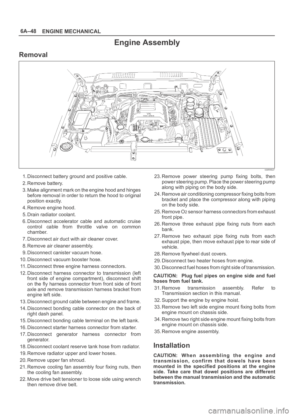
035RW027
1. Disconnect battery ground and positive cable.
2. Remove battery.
3. Make alignment mark on the engine hood and hinges
before removal in order to return the hood to original
position exactly.
4. Remove engine hood.
5. Drain radiator coolant.
6. Disconnect accelerator cable and automatic cruise
control cable from throttle valve on common
chamber.
7. Disconnect air duct with air cleaner cover.
8. Remove air cleaner assembly.
9. Disconnect canister vacuum hose.
10. Disconnect vacuum booster hose.
11. Disconnect three engine harness connectors.
12. Disconnect harness connector to transmission (left
front side of engine compartment), disconnect shift
on the fly harness connector from front side of front
axle and remove transmission harness bracket from
engine left side.
13. Disconnect ground cable between engine and frame.
14. Disconnect bonding cable connector on the back of
right dash panel.
15. Disconnect bonding cable terminal on the left bank.
16. Disconnect starter harness connector from starter.
17. Disconnect generator harness connector from
generator.
18. Disconnect coolant reserve tank hose from radiator.
19. Remove radiator upper and lower hoses.
20. Remove upper fan shroud.
21. Remove cooling fan assembly four fixing nuts, then
the cooling fan assembly.
22. Move drive belt tensioner to loose side using wrench
then remove drive belt.23. Remove power steering pump fixing bolts, then
power steering pump. Place the power steering pump
along with piping on the body side.
24. Remove air conditioning compressor fixing bolts from
bracket and place the compressor along with piping
on the body side.
25. Remove O
2 sensor harness connectors from exhaust
front pipe.
26. Remove three exhaust pipe fixing nuts from each
bank.
27. Remove two exhaust pipe fixing nuts from each
exhaust pipe, then move exhaust pipe to rear side of
vehicle.
28. Remove flywheel dust covers.
29. Disconnect two heater hoses from engine.
30. Disconnect fuel hoses from right side of transmission.
CAUTION: Plug fuel pipes on engine side and fuel
hoses from fuel tank.
31. Remove transmission assembly. Refer to
Transmission section in this manual.
32. Support the engine by engine hoist.
33. Remove two left side engine mount fixing bolts from
engine mount on chassis side.
34. Remove two right side engine mount fixing bolts from
engine mount on chassis side.
35. Remove engine assembly.
Installation
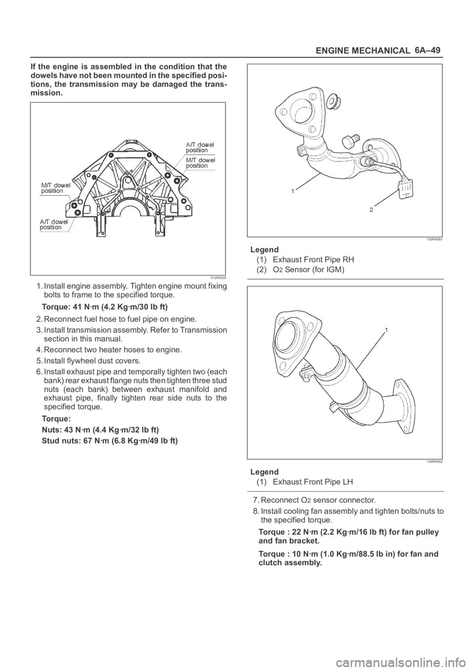
CAUTION: W h e n a s s e m b l i n g t h e e n g i n e a n d
transmission, confirm that dowels have been
mounted in the specified positions at the engine
side. Take care that dowel positions are different
between the manual transmission and the automatic
transmission.
Page 1005 of 6000
6A–49
ENGINE MECHANICAL
If the engine is assembled in the condition that the
dowels have not been mounted in the specified posi-
tions, the transmission may be damaged the trans-
mission.
012RS009
1. Install engine assembly. Tighten engine mount fixing
bolts to frame to the specified torque.
Torque: 41 Nꞏm (4.2 Kgꞏm/30 lb ft)
2. Reconnect fuel hose to fuel pipe on engine.
3. Install transmission assembly. Refer to Transmission
section in this manual.
4. Reconnect two heater hoses to engine.
5. Install flywheel dust covers.
6. Install exhaust pipe and temporally tighten two (each
bank) rear exhaust flange nuts then tighten three stud
nuts (each bank) between exhaust manifold and
exhaust pipe, finally tighten rear side nuts to the
specified torque.
Torque:
Nuts: 43 Nꞏm (4.4 Kgꞏm/32 lb ft)
Stud nuts: 67 Nꞏm (6.8 Kgꞏm/49 lb ft)
150RW061
Legend
(1) Exhaust Front Pipe RH
(2) O
2 Sensor (for IGM)
150RW062
Legend
(1) Exhaust Front Pipe LH
7. Reconnect O2 sensor connector.
8. Install cooling fan assembly and tighten bolts/nuts to
the specified torque.
Torque : 22 Nꞏm (2.2 Kgꞏm/16 lb ft) for fan pulley
and fan bracket.
Torque : 10 Nꞏm (1.0 Kgꞏm/88.5 lb in) for fan and
clutch assembly.
Page 1068 of 6000
6C–1
ENGINE FUEL
ENGINE
ENGINE FUEL
CONTENTS
Service Precaution 6C–1. . . . . . . . . . . . . . . . . . . . . .
General Description 6C–2. . . . . . . . . . . . . . . . . . . . .
Fuel Metering 6C–3. . . . . . . . . . . . . . . . . . . . . . . . . . .
Fuel Filter 6C–4. . . . . . . . . . . . . . . . . . . . . . . . . . . . . .
Fuel Filter and Associated Parts 6C–4. . . . . . . . .
Removal 6C–4. . . . . . . . . . . . . . . . . . . . . . . . . . . . .
Inspection 6C–4. . . . . . . . . . . . . . . . . . . . . . . . . . . .
Installation 6C–5. . . . . . . . . . . . . . . . . . . . . . . . . . . .
Inspection 6C–5. . . . . . . . . . . . . . . . . . . . . . . . . . . .
In–Tank Fuel Filter 6C–5. . . . . . . . . . . . . . . . . . . . .
Fuel Pump Flow Test 6C–5. . . . . . . . . . . . . . . . . . .
Fuel Pump 6C–6. . . . . . . . . . . . . . . . . . . . . . . . . . . . .
Fuel Pump and Associated Parts 6C–6. . . . . . . .
Removal 6C–6. . . . . . . . . . . . . . . . . . . . . . . . . . . . .
Installation 6C–6. . . . . . . . . . . . . . . . . . . . . . . . . . . .
Fuel Pump Relay 6C–7. . . . . . . . . . . . . . . . . . . . . . . .
General Description 6C–7. . . . . . . . . . . . . . . . . . . . .
Fuel Tank 6C–7. . . . . . . . . . . . . . . . . . . . . . . . . . . . . . Fuel Tank and Associated Parts 6C–7. . . . . . . . .
Removal 6C–7. . . . . . . . . . . . . . . . . . . . . . . . . . . . .
Installation 6C–8. . . . . . . . . . . . . . . . . . . . . . . . . . . .
Fuel Tube / Quick – Connect Fittings 6C–8. . . . . . .
Precautions 6C–8. . . . . . . . . . . . . . . . . . . . . . . . . . .
Cautions During Work 6C–8. . . . . . . . . . . . . . . . . .
Removal 6C–8. . . . . . . . . . . . . . . . . . . . . . . . . . . . .
Reuse of Quick–Connector 6C–10. . . . . . . . . . . . . . .
Assembling Advice 6C–10. . . . . . . . . . . . . . . . . . . . . .
Fuel Gauge Unit 6C–11. . . . . . . . . . . . . . . . . . . . . . . .
Fuel Gauge Unit and Associated Parts 6C–11. . .
Removal 6C–11. . . . . . . . . . . . . . . . . . . . . . . . . . . . .
Installation 6C–11. . . . . . . . . . . . . . . . . . . . . . . . . . . .
Fuel Filler Cap 6C–12. . . . . . . . . . . . . . . . . . . . . . . . . .
General Description 6C–12. . . . . . . . . . . . . . . . . . . . .
Inspection 6C–12. . . . . . . . . . . . . . . . . . . . . . . . . . . .
Main Data and Specifications 6C–12. . . . . . . . . . . . .
Service Precaution
WARNING: IF SO EQUIPPED WITH A
SUPPLEMENTAL RESTRAINT SYSTEM (SRS),
REFER TO THE SRS COMPONENT AND WIRING
LOCATION VIEW IN ORDER TO DETERMINE
WHETHER YOU ARE PERFORMING SERVICE ON OR
NEAR THE SRS COMPONENTS OR THE SRS
WIRING. WHEN YOU ARE PERFORMING SERVICE
ON OR NEAR THE SRS COMPONENTS OR THE SRS
WIRING, REFER TO THE SRS SERVICE
INFORMATION. FAILURE TO FOLLOW WARNINGS
COULD RESULT IN POSSIBLE AIR BAG
DEPLOYMENT, PERSONAL INJURY, OR
OTHERWISE UNNEEDED SRS SYSTEM REPAIRS.
CAUTION: Always use the correct fastener in the
proper location. When you replace a fastener, use
ONLY the exact part number for that application.
ISUZU will call out those fasteners that require a
replacement after removal. ISUZU will also call out
the fasteners that require thread lockers or thread
sealant. UNLESS OTHERWISE SPECIFIED, do not
use supplemental coatings (Paints, greases, or other
corrosion inhibitors) on threaded fasteners or
fastener joint interfaces. Generally, such coatings
adversely affect the fastener torque and the joint
clamping force, and may damage the fastener. When
you install fasteners, use the correct tightening
sequence and specifications. Following these
instructions can help you avoid damage to parts and
systems.
Page 1069 of 6000
6C–2
ENGINE FUEL
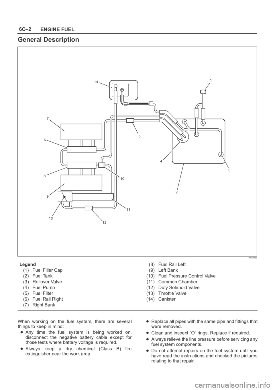
General Description
140RW030
Legend
(1) Fuel Filler Cap
(2) Fuel Tank
(3) Rollover Valve
(4) Fuel Pump
(5) Fuel Filter
(6) Fuel Rail Right
(7) Right Bank(8) Fuel Rail Left
(9) Left Bank
(10) Fuel Pressure Control Valve
(11) Common Chamber
(12) Duty Solenoid Valve
(13) Throttle Valve
(14) Canister
When working on the fuel system, there are several
things to keep in mind:
Any time the fuel system is being worked on,
disconnect the negative battery cable except for
those tests where battery voltage is required.
Always keep a dry chemical (Class B) fire
extinguisher near the work area.
Replace all pipes with the same pipe and fittings that
were removed.
Clean and inspect “O” rings. Replace if required.
Always relieve the line pressure before servicing any
fuel system components.
Do not attempt repairs on the fuel system until you
have read the instructions and checked the pictures
relating to that repair.
Page 1070 of 6000
6C–3
ENGINE FUEL
Adhere to all Notices and Cautions.
All gasoline engines are designed to use only unleaded
gasoline. Unleaded gasoline must be used for proper
emission control system operation.
Its use will also minimize spark plug fouling and extend
engine oil life. Using leaded gasoline can damage the
emission control system and could result in loss of
emission warranty coverage.
All cars are equipped with an Evaporative Emission
Control System. The purpose of the system is to minimize
the escape of fuel vapors to the atmosphere.
Fuel Metering
The Engine Control Module (ECM) is in complete control
of this fuel delivery system during normal driving
conditions.
The intake manifold function, like that of a diesel, is used
only to let air into the engine. The fuel is injected by
separate injectors that are mounted over the intake
manifold.
The Manifold Absolute Pressure (MAP) sensor measures
the changes in the intake manifold pressure which result
from engine load and speed changes, which the MAP
sensor converts to a voltage output.
This sensor generates the voltage to change
corresponding to the flow of the air drawn into the engine.
The changing voltage is transformed into an electric
signal and provided to the ECM.
With receipt of the signals sent from the MAP sensor,
Intake Air Temperature sensor and others, the ECM
determines an appropriate fuel injection pulse width
feeding such information to the fuel injector valves to
effect an appropriate air/fuel ratio.
The Multiport Fuel Injection system utilizes an injection
system where the injectors turn on at every crankshaft
re vol u tion . Th e EC M con tro ls t he in je cto r on tim e so t ha t
the correct amount of fuel is metered depending on
driving conditions.
Two interchangeable “O” rings are used on the injector
that must be replaced when the injectors are removed.
The fuel rail is attached to the top of the intake manifold
and supplies fuel to all the injectors.
Fuel is recirculated through the rail continually while the
engine is running. This removes air and vapors from the
fuel as well as keeping the fuel cool during hot weather
operation.
The fuel pressure control valve that is mounted on the fuel
rail maintains a pressure differential across the injectors
under all operating conditions. It is accomplished by
controlling the amount of fuel that is recirculated back to
the fuel tank based on engine demand.
See Section “Driveability and Emission” for more
information and diagnosis.