1998 OPEL FRONTERA display
[x] Cancel search: displayPage 2060 of 6000
6E–167 4JX1–TC ENGINE DRIVEABILITY AND EMISSIONS
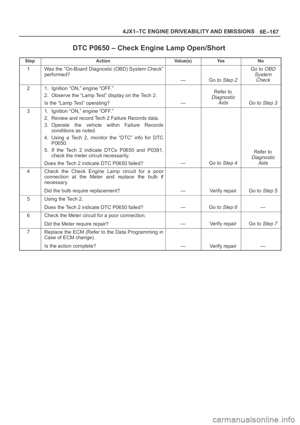
DTC P0650 – Check Engine Lamp Open/Short
StepActionVa l u e ( s )Ye sNo
1Was the “On-Board Diagnostic (OBD) System Check”
performed?
—Go to Step 2
Go to OBD
System
Check
21. Ignition “ON,” engine “OFF.”
2. Observe the “Lamp Test” display on the Tech 2.
Is the “Lamp Test” operating?
—
Refer to
Diagnostic
Aids
Go to Step 3
31. Ignition “ON,” engine “OFF.”
2. Review and record Tech 2 Failure Records data.
3. Operate the vehicle within Failure Records
conditions as noted.
4. Using a Tech 2, monitor the “DTC” info for DTC
P0650.
5. If the Tech 2 indicate DTCs P0650 and P0381,
check the meter circuit necessarily.
Does the Tech 2 indicate DTC P0650 failed?
—Go to Step 4
Refer to
Diagnostic
Aids
4Check the Check Engine Lamp circuit for a poor
connection at the Meter and replace the bulb if
necessary.
Did the bulb require replacement?
—Verify repairGo to Step 5
5Using the Tech 2.
Does the Tech 2 indicate DTC P0650 failed?
—Go to Step 6—
6Check the Meter circuit for a poor connection.
Did the Meter require repair?
—Verify repairGo to Step 7
7Replace the ECM (Refer to the Data Programming in
Case of ECM change).
Is the action complete?
—Verify repair—
Page 2064 of 6000
6E–171 4JX1–TC ENGINE DRIVEABILITY AND EMISSIONS
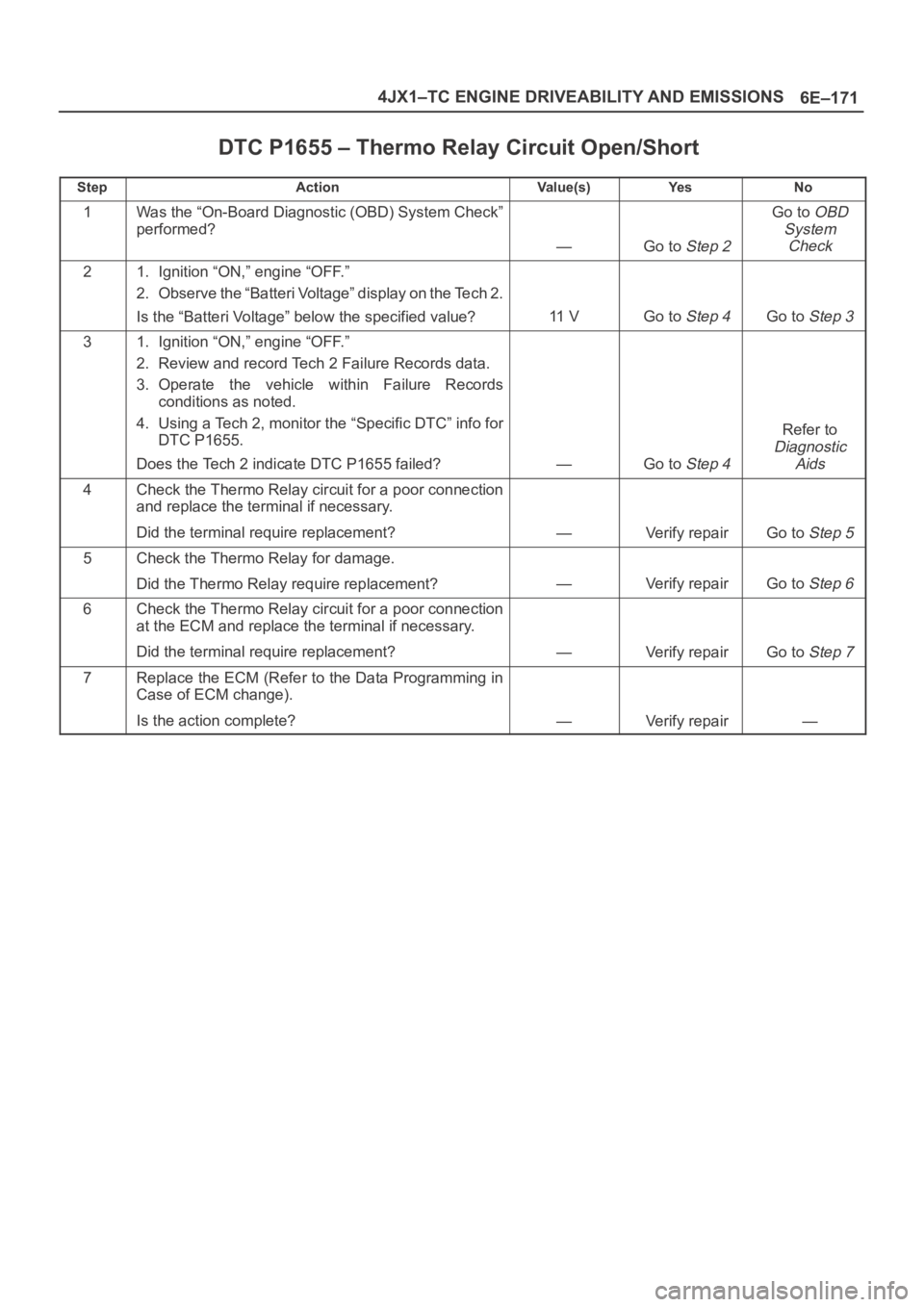
DTC P1655 – Thermo Relay Circuit Open/Short
StepActionVa l u e ( s )Ye sNo
1Was the “On-Board Diagnostic (OBD) System Check”
performed?
—Go to Step 2
Go to OBD
System
Check
21. Ignition “ON,” engine “OFF.”
2. Observe the “Batteri Voltage” display on the Tech 2.
Is the “Batteri Voltage” below the specified value?
11 VGo to Step 4Go to Step 3
31. Ignition “ON,” engine “OFF.”
2. Review and record Tech 2 Failure Records data.
3. Operate the vehicle within Failure Records
conditions as noted.
4. Using a Tech 2, monitor the “Specific DTC” info for
DTC P1655.
Does the Tech 2 indicate DTC P1655 failed?
—Go to Step 4
Refer to
Diagnostic
Aids
4Check the Thermo Relay circuit for a poor connection
and replace the terminal if necessary.
Did the terminal require replacement?
—Verify repairGo to Step 5
5Check the Thermo Relay for damage.
Did the Thermo Relay require replacement?
—Verify repairGo to Step 6
6Check the Thermo Relay circuit for a poor connection
at the ECM and replace the terminal if necessary.
Did the terminal require replacement?
—Verify repairGo to Step 7
7Replace the ECM (Refer to the Data Programming in
Case of ECM change).
Is the action complete?
—Verify repair—
Page 2067 of 6000
6E–174
4JX1–TC ENGINE DRIVEABILITY AND EMISSIONS
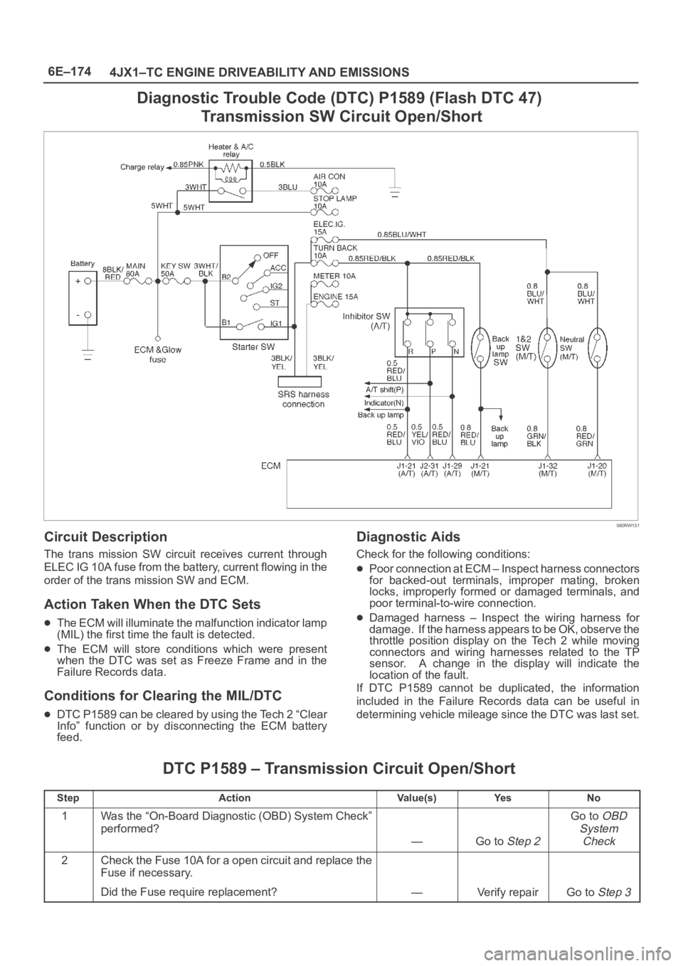
Diagnostic Trouble Code (DTC) P1589 (Flash DTC 47)
Transmission SW Circuit Open/Short
060RW131
Circuit Description
The trans mission SW circuit receives current through
ELEC IG 10A fuse from the battery, current flowing in the
order of the trans mission SW and ECM.
Action Taken When the DTC Sets
The ECM will illuminate the malfunction indicator lamp
(MIL) the first time the fault is detected.
The ECM will store conditions which were present
when the DTC was set as Freeze Frame and in the
Failure Records data.
Conditions for Clearing the MIL/DTC
DTC P1589 can be cleared by using the Tech 2 “Clear
Info” function or by disconnecting the ECM battery
feed.
Diagnostic Aids
Check for the following conditions:
Poor connection at ECM – Inspect harness connectors
for backed-out terminals, improper mating, broken
locks, improperly formed or damaged terminals, and
poor terminal-to-wire connection.
Damaged harness – Inspect the wiring harness for
damage. If the harness appears to be OK, observe the
throttle position display on the Tech 2 while moving
connectors and wiring harnesses related to the TP
sensor. A change in the display will indicate the
location of the fault.
If DTC P1589 cannot be duplicated, the information
included in the Failure Records data can be useful in
determining vehicle mileage since the DTC was last set.
DTC P1589 – Transmission Circuit Open/Short
StepActionVa l u e ( s )Ye sNo
1Was the “On-Board Diagnostic (OBD) System Check”
performed?
—Go to Step 2
Go to OBD
System
Check
2Check the Fuse 10A for a open circuit and replace the
Fuse if necessary.
Did the Fuse require replacement?
—Verify repairGo to Step 3
Page 2070 of 6000
6E–177 4JX1–TC ENGINE DRIVEABILITY AND EMISSIONS
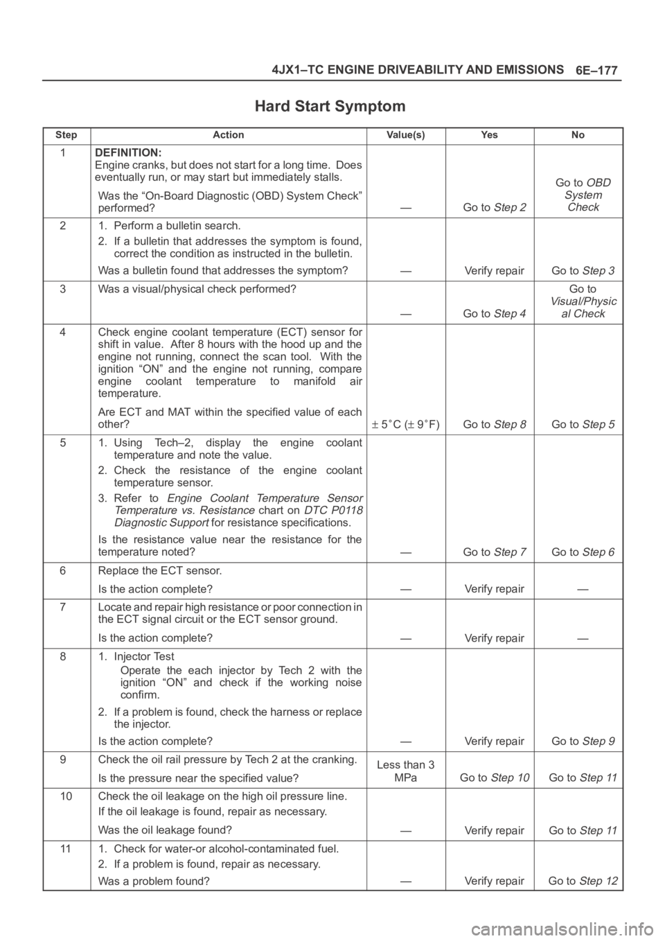
Hard Start Symptom
StepActionVa l u e ( s )Ye sNo
1DEFINITION:
Engine cranks, but does not start for a long time. Does
eventually run, or may start but immediately stalls.
Was the “On-Board Diagnostic (OBD) System Check”
performed?
—Go to Step 2
Go to OBD
System
Check
21. Perform a bulletin search.
2. If a bulletin that addresses the symptom is found,
correct the condition as instructed in the bulletin.
Was a bulletin found that addresses the symptom?
—Verify repairGo to Step 3
3Was a visual/physical check performed?
—Go to Step 4
Go to
Visual/Physic
al Check
4Check engine coolant temperature (ECT) sensor for
shift in value. After 8 hours with the hood up and the
engine not running, connect the scan tool. With the
ignition “ON” and the engine not running, compare
engine coolant temperature to manifold air
temperature.
Are ECT and MAT within the specified value of each
other?
5C ( 9F)Go to Step 8Go to Step 5
51. Using Tech–2, display the engine coolant
temperature and note the value.
2. Check the resistance of the engine coolant
temperature sensor.
3. Refer to
Engine Coolant Temperature Sensor
Temperature vs. Resistance
chart on DTC P0118
Diagnostic Support
for resistance specifications.
Is the resistance value near the resistance for the
temperature noted?
—Go to Step 7Go to Step 6
6Replace the ECT sensor.
Is the action complete?
—Verify repair—
7Locate and repair high resistance or poor connection in
the ECT signal circuit or the ECT sensor ground.
Is the action complete?
—Verify repair—
81. Injector Test
Operate the each injector by Tech 2 with the
ignition “ON” and check if the working noise
confirm.
2. If a problem is found, check the harness or replace
the injector.
Is the action complete?
—Verify repairGo to Step 9
9Check the oil rail pressure by Tech 2 at the cranking.
Is the pressure near the specified value?Less than 3
MPa
Go to Step 10Go to Step 11
10Check the oil leakage on the high oil pressure line.
If the oil leakage is found, repair as necessary.
Was the oil leakage found?
—Verify repairGo to Step 11
111. Check for water-or alcohol-contaminated fuel.
2. If a problem is found, repair as necessary.
Was a problem found?
—Verify repairGo to Step 12
Page 2079 of 6000
6E–186
4JX1–TC ENGINE DRIVEABILITY AND EMISSIONS
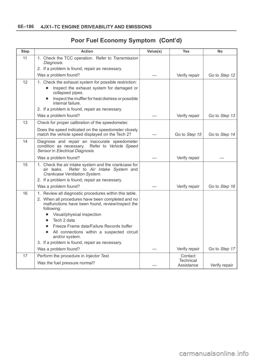
Poor Fuel Economy Symptom
StepNo Ye s Va l u e ( s ) Action
111. Check the TCC operation. Refer to Transmission
Diagnosis
.
2. If a problem is found, repair as necessary.
Was a problem found?
—Verify repairGo to Step 12
121. Check the exhaust system for possible restriction:
Inspect the exhaust system for damaged or
collapsed pipes.
Inspect the muffler for heat distress or possible
internal failure.
2. If a problem is found, repair as necessary.
Was a problem found?
—Verify repairGo to Step 13
13Check for proper calibration of the speedometer.
Does the speed indicated on the speedometer closely
match the vehicle speed displayed on the Tech 2?
—Go to Step 15Go to Step 14
14Diagnose and repair an inaccurate speedometer
condition as necessary. Refer to
Vehicle Speed
Sensor
in Electrical Diagnosis.
Was a problem found?
—Verify repair—
151. Check the air intake system and the crankcase for
air leaks. Refer to
Air Intake System and
Crankcase Ventilation System.
2. If a problem is found, repair as necessary.
Was a problem found?
—Verify repairGo to Step 16
161. Review all diagnostic procedures within this table.
2. When all procedures have been completed and no
malfunctions have been found, review/inspect the
following:
Visual/physical inspection
Te c h 2 d a t a
Freeze Frame data/Failure Records buffer
All connections within a suspected circuit
and/or system.
3. If a problem is found, repair as necessary.
Was a problem found?
—Verify repairGo to Step 17
17Perform the procedure in Injector Test.
Was the fuel pressure normal?
—
Contact
Te c h n i c a l
Assistance
Verify repair
Page 2118 of 6000
6E–225 4JX1–TC ENGINE DRIVEABILITY AND EMISSIONS
General Description
(ECM and Sensors)
57X Reference ECM Input
The engine control module (ECM) uses this signal from
the crankshaft position (CKP) sensor to calculate engine
RPM and crankshaft position at all engine speeds. The
ECM also uses the pulses on this circuit to initiate injector
pulses. If the ECM receives no pulses on this circuit, DTC
P0337 will set. The engine will not start and run without
using the 57X reference signal.
A/C Request Signal
This signal tells the ECM when the A/C mode is selected
at the A/C control head.
Refer to
A/C Clutch Circuit Diagnosis for A/C wiring
diagrams and diagnosis for the A/C electrical system.
Crankshaft Position (CKP) Sensor
The crankshaft position (CKP) sensor provides a signal
used by the engine control module (ECM) to calculate the
ignition sequence. The CKP sensor initiates the 57X
reference pulses which the ECM uses to calculate RPM
and crankshaft position.
Refer to
Electronic Ignition System for additional
information.
Camshaft Position (CMP) Sensor and
Signal
The camshaft position (CMP) sensor sends a CMP signal
to the ECM. The ECM uses this signal as a “cylinder
distinction” to trigger the injectors in the power order. If the
ECM detects an incorrect CMP signal while the engine is
running, DTC P0341 will set, and the ECM triggers the
injectors in the power order.
Refer to
DTC P0341.
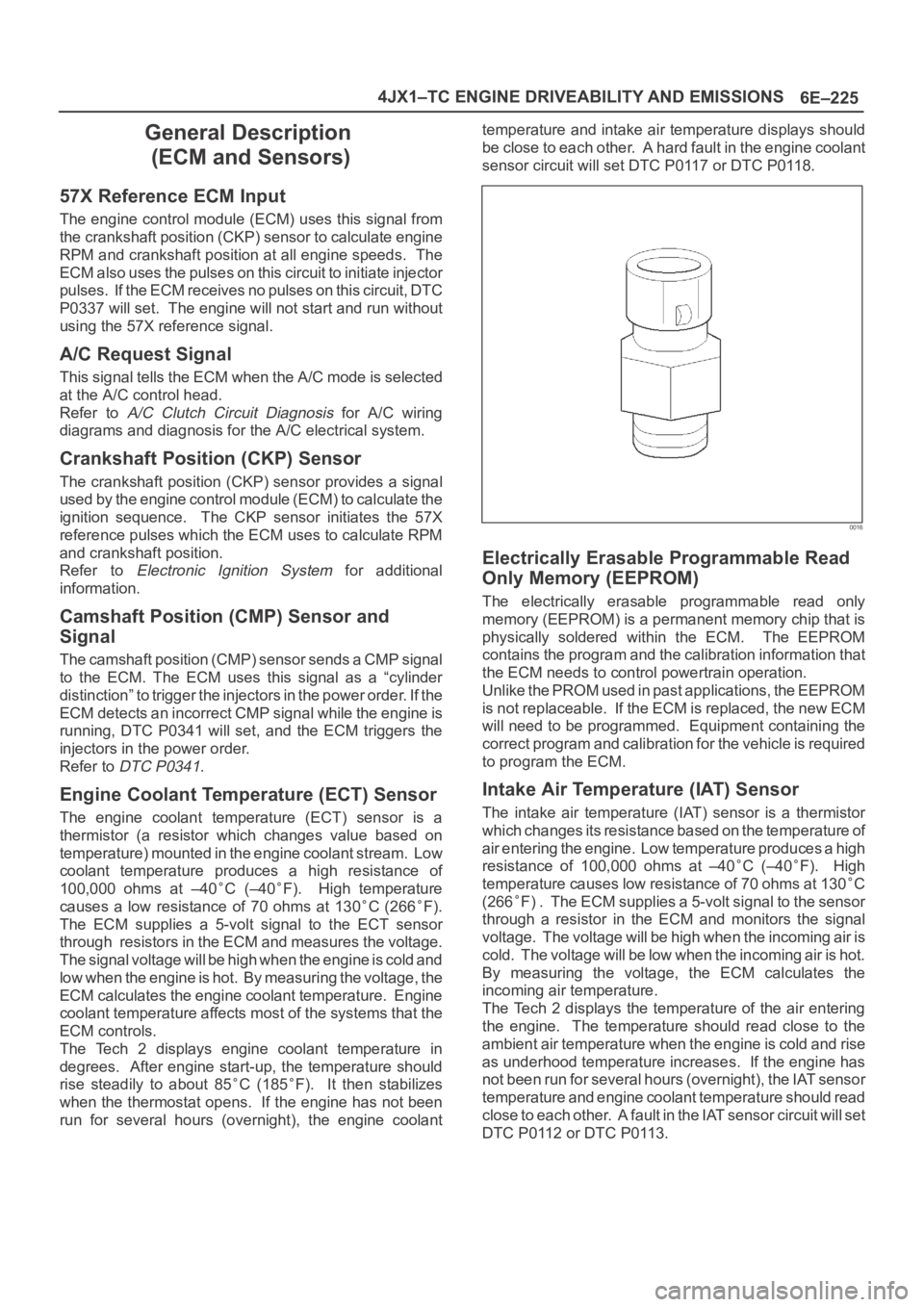
Engine Coolant Temperature (ECT) Sensor
The engine coolant temperature (ECT) sensor is a
thermistor (a resistor which changes value based on
temperature) mounted in the engine coolant stream. Low
coolant temperature produces a high resistance of
100,000 ohms at –40
C (–40F). High temperature
causes a low resistance of 70 ohms at 130
C (266F).
The ECM supplies a 5-volt signal to the ECT sensor
through resistors in the ECM and measures the voltage.
The signal voltage will be high when the engine is cold and
low when the engine is hot. By measuring the voltage, the
ECM calculates the engine coolant temperature. Engine
coolant temperature affects most of the systems that the
ECM controls.
The Tech 2 displays engine coolant temperature in
degrees. After engine start-up, the temperature should
rise steadily to about 85
C (185F). It then stabilizes
when the thermostat opens. If the engine has not been
run for several hours (overnight), the engine coolanttemperature and intake air temperature displays should
be close to each other. A hard fault in the engine coolant
sensor circuit will set DTC P0117 or DTC P0118.
0016
Electrically Erasable Programmable Read
Only Memory (EEPROM)
The electrically erasable programmable read only
memory (EEPROM) is a permanent memory chip that is
physically soldered within the ECM. The EEPROM
contains the program and the calibration information that
the ECM needs to control powertrain operation.
Unlike the PROM used in past applications, the EEPROM
is not replaceable. If the ECM is replaced, the new ECM
will need to be programmed. Equipment containing the
correct program and calibration for the vehicle is required
to program the ECM.
Intake Air Temperature (IAT) Sensor
The intake air temperature (IAT) sensor is a thermistor
which changes its resistance based on the temperature of
air entering the engine. Low temperature produces a high
resistance of 100,000 ohms at –40
C (–40F). High
temperature causes low resistance of 70 ohms at 130
C
(266
F) . The ECM supplies a 5-volt signal to the sensor
through a resistor in the ECM and monitors the signal
voltage. The voltage will be high when the incoming air is
cold. The voltage will be low when the incoming air is hot.
By measuring the voltage, the ECM calculates the
incoming air temperature.
The Tech 2 displays the temperature of the air entering
the engine. The temperature should read close to the
ambient air temperature when the engine is cold and rise
as underhood temperature increases. If the engine has
not been run for several hours (overnight), the IAT sensor
temperature and engine coolant temperature should read
close to each other. A fault in the IAT sensor circuit will set
DTC P0112 or DTC P0113.
Page 2251 of 6000
7A1–6
TRANSMISSION CONTROL SYSTEM (4L30–E)
Shift Control
The transmission gear is shifted according to the shift
pattern selected by the driver. In shifting gears, the gear
ratio is controlled by the ON/ OFF signal using the shift
solenoid A and the shift solenoid B.
Band Apply Control
The band apply is controlled when in the 3–2 downshift
(engine overrun prevention) and the garage shift (shock
control).
The band apply solenoid is controlled by the signal from
the Pulse Width Modulation (PWM) to regulate the flow of
the oil.
Torque Converter Clutch Control
The clutch ON/OFF is controlled by moving the converter
clutch valve through shifting Torque Converter Clutch
(TCC) solenoid using the ON/OFF signal.
Line Pressure Control
The throttle signal allows the current signal to be sent to
the force motor. After receiving the current signal, the
force motor activates the pressure regulator valve to
regulate the line pressure.
On–Board Diagnostic System
Several malfunction displays can be stored in the
Powertrain Control Module (PCM) memory, and read out
of it afterward.The serial data lines, which are required for the testing of
the final assembly and the coupling to other electronic
modules, can be regulated by this function.
Fail Safe Mechanism
If there is a problem in the transmission system, the PCM
will go into a “backup” mode.
The vehicle can still be driven, but the driver must use the
select lever to shift gears.
Torque Management Control
The transmission control side sends the absolute spark
advance signal to the engine control side while the
transmission is being shifted. This controls the engine
spark timing in compliance with the vehicle running
condition to reduce the shocks caused by the change of
speed.
ATF Warning Control
The oil temperature sensor detects the ATF oil
temperature to control the oil temperature warning, TCC,
and the winter mode.
ABS Control (If equipped)
When the select lever is at “L” or “R” range, a signal is sent
to the ABS controller as one of the ABS control
conditions.
Page 2260 of 6000
TRANSMISSION CONTROL SYSTEM (4L30–E)7A1–15
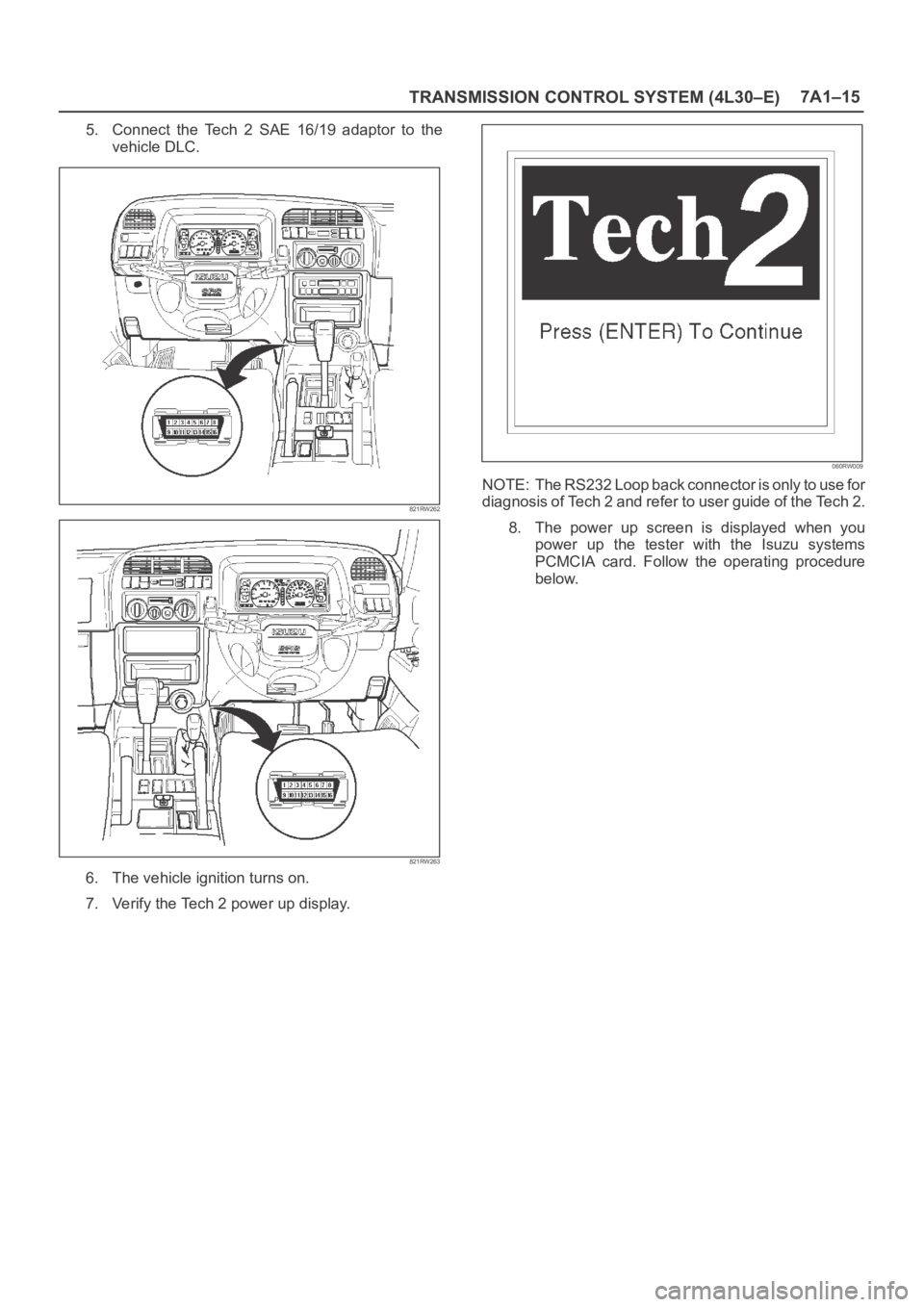
5. Connect the Tech 2 SAE 16/19 adaptor to the
vehicle DLC.
821RW262
821RW263
6. The vehicle ignition turns on.
7. Verify the Tech 2 power up display.
060RW009
NOTE: The RS232 Loop back connector is only to use for
diagnosis of Tech 2 and refer to user guide of the Tech 2.
8. The power up screen is displayed when you
power up the tester with the Isuzu systems
PCMCIA card. Follow the operating procedure
below.