1998 OPEL FRONTERA coolant temperature
[x] Cancel search: coolant temperaturePage 4898 of 6000
6E–241 ENGINE DRIVEABILITY AND EMISSIONS
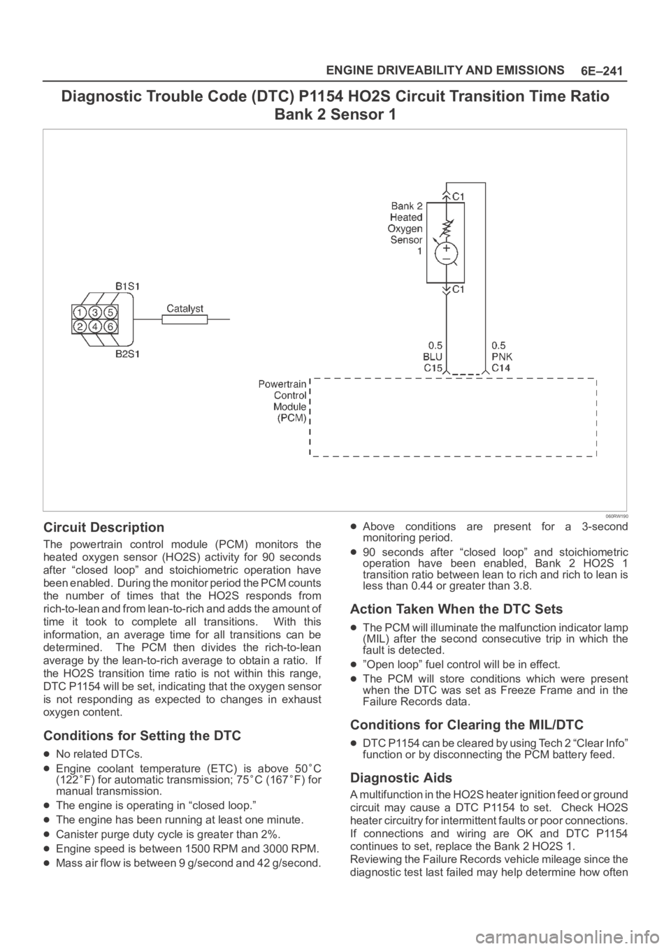
Diagnostic Trouble Code (DTC) P1154 HO2S Circuit Transition Time Ratio
Bank 2 Sensor 1
060RW190
Circuit Description
The powertrain control module (PCM) monitors the
heated oxygen sensor (HO2S) activity for 90 seconds
after “closed loop” and stoichiometric operation have
been enabled. During the monitor period the PCM counts
the number of times that the HO2S responds from
rich-to-lean and from lean-to-rich and adds the amount of
time it took to complete all transitions. With this
information, an average time for all transitions can be
determined. The PCM then divides the rich-to-lean
average by the lean-to-rich average to obtain a ratio. If
the HO2S transition time ratio is not within this range,
DTC P1154 will be set, indicating that the oxygen sensor
is not responding as expected to changes in exhaust
oxygen content.
Conditions for Setting the DTC
No related DTCs.
Engine coolant temperature (ETC) is above 50C
(122F) for automatic transmission; 75C (167F) for
manual transmission.
The engine is operating in “closed loop.”
The engine has been running at least one minute.
Canister purge duty cycle is greater than 2%.
Engine speed is between 1500 RPM and 3000 RPM.
Mass air flow is between 9 g/second and 42 g/second.
Above conditions are present for a 3-second
monitoring period.
90 seconds after “closed loop” and stoichiometric
operation have been enabled, Bank 2 HO2S 1
transition ratio between lean to rich and rich to lean is
less than 0.44 or greater than 3.8.
Action Taken When the DTC Sets
The PCM will illuminate the malfunction indicator lamp
(MIL) after the second consecutive trip in which the
fault is detected.
”Open loop” fuel control will be in effect.
The PCM will store conditions which were present
when the DTC was set as Freeze Frame and in the
Failure Records data.
Conditions for Clearing the MIL/DTC
DTC P1154 can be cleared by using Tech 2 “Clear Info”
function or by disconnecting the PCM battery feed.
Diagnostic Aids
A multifunction in the HO2S heater ignition feed or ground
circuit may cause a DTC P1154 to set. Check HO2S
heater circuitry for intermittent faults or poor connections.
If connections and wiring are OK and DTC P1154
continues to set, replace the Bank 2 HO2S 1.
Reviewing the Failure Records vehicle mileage since the
diagnostic test last failed may help determine how often
Page 4902 of 6000
6E–245 ENGINE DRIVEABILITY AND EMISSIONS
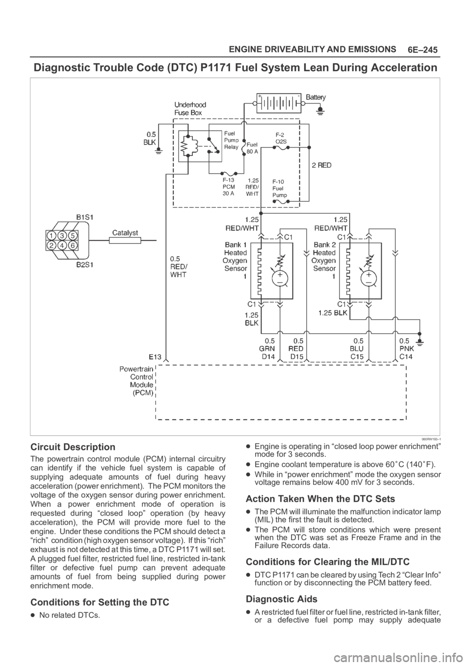
Diagnostic Trouble Code (DTC) P1171 Fuel System Lean During Acceleration
060RW193–1
Circuit Description
The powertrain control module (PCM) internal circuitry
can identify if the vehicle fuel system is capable of
supplying adequate amounts of fuel during heavy
acceleration (power enrichment). The PCM monitors the
voltage of the oxygen sensor during power enrichment.
When a power enrichment mode of operation is
requested during “closed loop” operation (by heavy
acceleration), the PCM will provide more fuel to the
engine. Under these conditions the PCM should detect a
“rich” condition (high oxygen sensor voltage). If this “rich”
exhaust is not detected at this time, a DTC P1171 will set.
A plugged fuel filter, restricted fuel line, restricted in-tank
filter or defective fuel pump can prevent adequate
amounts of fuel from being supplied during power
enrichment mode.
Conditions for Setting the DTC
No related DTCs.
Engine is operating in “closed loop power enrichment”
mode for 3 seconds.
Engine coolant temperature is above 60C (140F).
While in “power enrichment” mode the oxygen sensor
voltage remains below 400 mV for 3 seconds.
Action Taken When the DTC Sets
The PCM will illuminate the malfunction indicator lamp
(MIL) the first the fault is detected.
The PCM will store conditions which were present
when the DTC was set as Freeze Frame and in the
Failure Records data.
Conditions for Clearing the MIL/DTC
DTC P1171 can be cleared by using Tech 2 “Clear Info”
function or by disconnecting the PCM battery feed.
Diagnostic Aids
A restricted fuel filter or fuel line, restricted in-tank filter,
or a defective fuel pomp may supply adequate
Page 4908 of 6000
6E–251 ENGINE DRIVEABILITY AND EMISSIONS
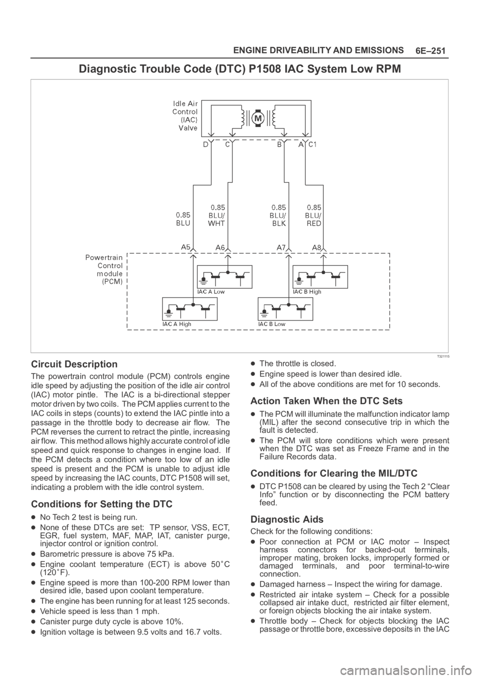
Diagnostic Trouble Code (DTC) P1508 IAC System Low RPM
T321115
Circuit Description
The powertrain control module (PCM) controls engine
idle speed by adjusting the position of the idle air control
(IAC) motor pintle. The IAC is a bi-directional stepper
motor driven by two coils. The PCM applies current to the
IAC coils in steps (counts) to extend the IAC pintle into a
passage in the throttle body to decrease air flow. The
PCM reverses the current to retract the pintle, increasing
air flow. This method allows highly accurate control of idle
speed and quick response to changes in engine load. If
the PCM detects a condition where too low of an idle
speed is present and the PCM is unable to adjust idle
speed by increasing the IAC counts, DTC P1508 will set,
indicating a problem with the idle control system.
Conditions for Setting the DTC
No Tech 2 test is being run.
None of these DTCs are set: TP sensor, VSS, ECT,
EGR, fuel system, MAF, MAP, IAT, canister purge,
injector control or ignition control.
Barometric pressure is above 75 kPa.
Engine coolant temperature (ECT) is above 50C
(120
F).
Engine speed is more than 100-200 RPM lower than
desired idle, based upon coolant temperature.
The engine has been running for at least 125 seconds.
Vehicle speed is less than 1 mph.
Canister purge duty cycle is above 10%.
Ignition voltage is between 9.5 volts and 16.7 volts.
The throttle is closed.
Engine speed is lower than desired idle.
All of the above conditions are met for 10 seconds.
Action Taken When the DTC Sets
The PCM will illuminate the malfunction indicator lamp
(MIL) after the second consecutive trip in which the
fault is detected.
The PCM will store conditions which were present
when the DTC was set as Freeze Frame and in the
Failure Records data.
Conditions for Clearing the MIL/DTC
DTC P1508 can be cleared by using the Tech 2 “Clear
Info” function or by disconnecting the PCM battery
feed.
Diagnostic Aids
Check for the following conditions:
Poor connection at PCM or IAC motor – Inspect
harness connectors for backed-out terminals,
improper mating, broken locks, improperly formed or
damaged terminals, and poor terminal-to-wire
connection.
Damaged harness – Inspect the wiring for damage.
Restricted air intake system – Check for a possible
collapsed air intake duct, restricted air filter element,
or foreign objects blocking the air intake system.
Throttle body – Check for objects blocking the IAC
passage or throttle bore, excessive deposits in the IAC
Page 4911 of 6000
6E–254
ENGINE DRIVEABILITY AND EMISSIONS
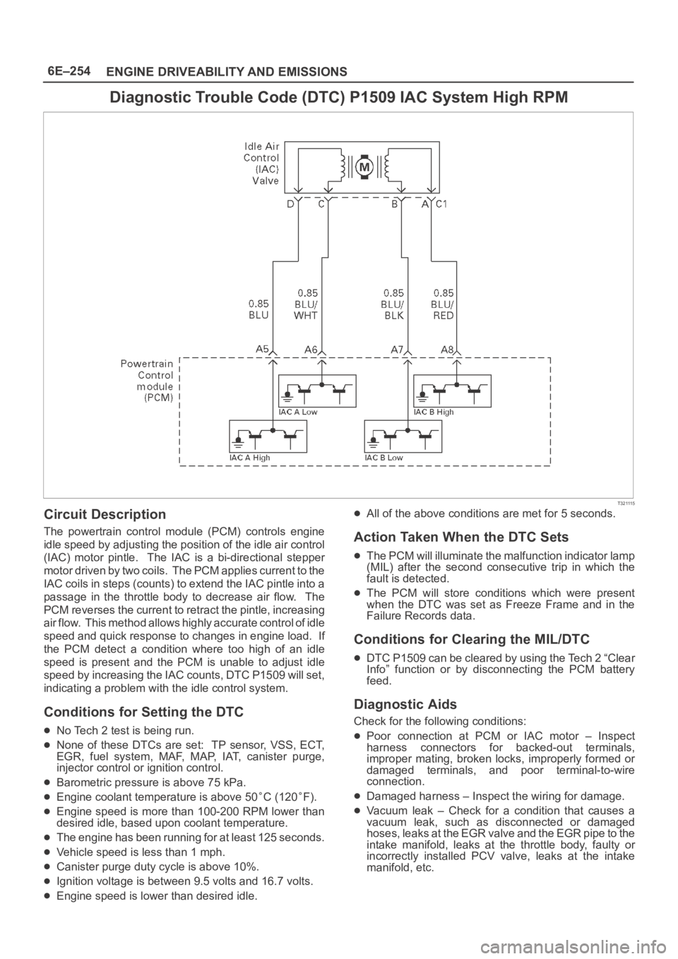
Diagnostic Trouble Code (DTC) P1509 IAC System High RPM
T321115
Circuit Description
The powertrain control module (PCM) controls engine
idle speed by adjusting the position of the idle air control
(IAC) motor pintle. The IAC is a bi-directional stepper
motor driven by two coils. The PCM applies current to the
IAC coils in steps (counts) to extend the IAC pintle into a
passage in the throttle body to decrease air flow. The
PCM reverses the current to retract the pintle, increasing
air flow. This method allows highly accurate control of idle
speed and quick response to changes in engine load. If
the PCM detect a condition where too high of an idle
speed is present and the PCM is unable to adjust idle
speed by increasing the IAC counts, DTC P1509 will set,
indicating a problem with the idle control system.
Conditions for Setting the DTC
No Tech 2 test is being run.
None of these DTCs are set: TP sensor, VSS, ECT,
EGR, fuel system, MAF, MAP, IAT, canister purge,
injector control or ignition control.
Barometric pressure is above 75 kPa.
Engine coolant temperature is above 50C (120F).
Engine speed is more than 100-200 RPM lower than
desired idle, based upon coolant temperature.
The engine has been running for at least 125 seconds.
Vehicle speed is less than 1 mph.
Canister purge duty cycle is above 10%.
Ignition voltage is between 9.5 volts and 16.7 volts.
Engine speed is lower than desired idle.
All of the above conditions are met for 5 seconds.
Action Taken When the DTC Sets
The PCM will illuminate the malfunction indicator lamp
(MIL) after the second consecutive trip in which the
fault is detected.
The PCM will store conditions which were present
when the DTC was set as Freeze Frame and in the
Failure Records data.
Conditions for Clearing the MIL/DTC
DTC P1509 can be cleared by using the Tech 2 “Clear
Info” function or by disconnecting the PCM battery
feed.
Diagnostic Aids
Check for the following conditions:
Poor connection at PCM or IAC motor – Inspect
harness connectors for backed-out terminals,
improper mating, broken locks, improperly formed or
damaged terminals, and poor terminal-to-wire
connection.
Damaged harness – Inspect the wiring for damage.
Vacuum leak – Check for a condition that causes a
vacuum leak, such as disconnected or damaged
h o s e s , l e a k s a t t h e E G R v a l v e a n d t h e E G R p i p e t o t h e
intake manifold, leaks at the throttle body, faulty or
incorrectly installed PCV valve, leaks at the intake
manifold, etc.
Page 4920 of 6000
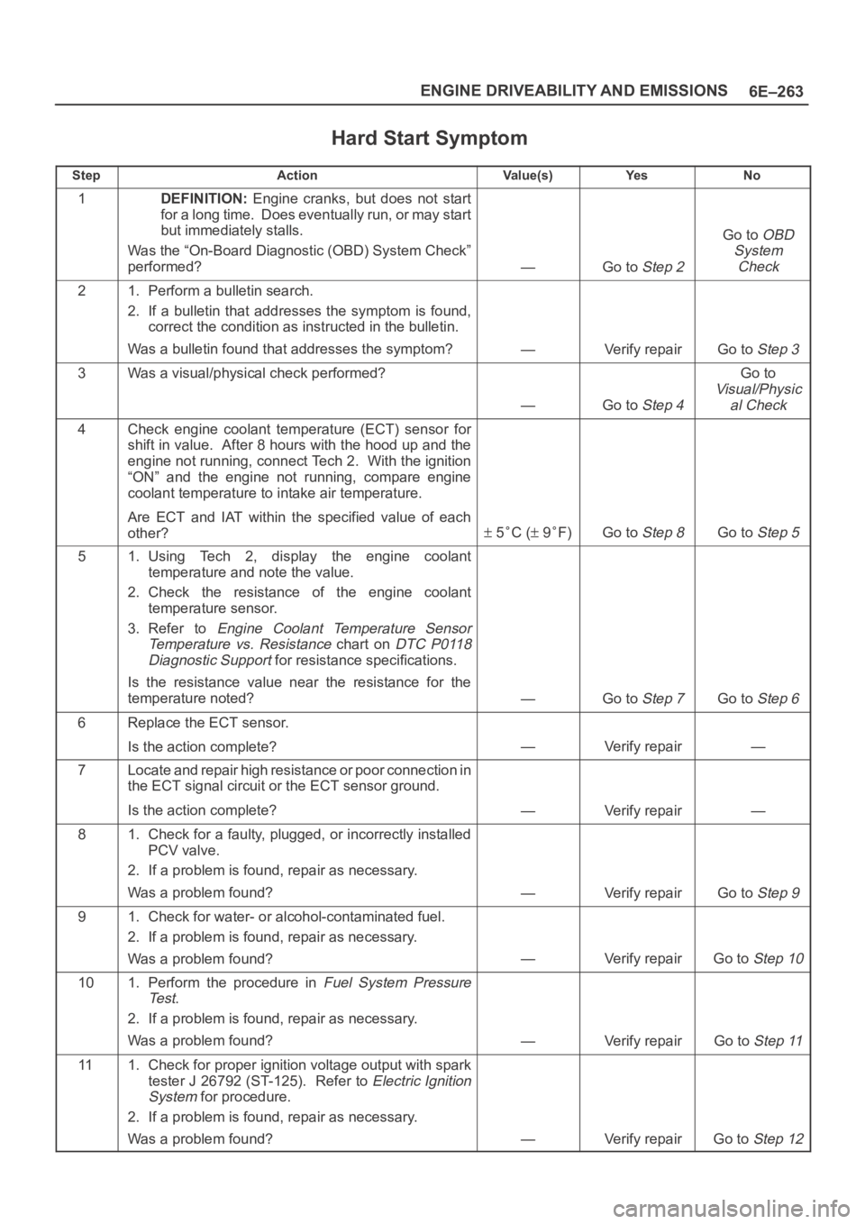
6E–263 ENGINE DRIVEABILITY AND EMISSIONS
Hard Start Symptom
StepActionVa l u e ( s )Ye sNo
1DEFINITION: Engine cranks, but does not start
for a long time. Does eventually run, or may start
but immediately stalls.
Was the “On-Board Diagnostic (OBD) System Check”
performed?
—Go to Step 2
Go to OBD
System
Check
21. Perform a bulletin search.
2. If a bulletin that addresses the symptom is found,
correct the condition as instructed in the bulletin.
Was a bulletin found that addresses the symptom?
—Verify repairGo to Step 3
3Was a visual/physical check performed?
—Go to Step 4
Go to
Visual/Physic
al Check
4Check engine coolant temperature (ECT) sensor for
shift in value. After 8 hours with the hood up and the
engine not running, connect Tech 2. With the ignition
“ON” and the engine not running, compare engine
coolant temperature to intake air temperature.
Are ECT and IAT within the specified value of each
other?
5C ( 9F)Go to Step 8Go to Step 5
51. Using Tech 2, display the engine coolant
temperature and note the value.
2. Check the resistance of the engine coolant
temperature sensor.
3. Refer to
Engine Coolant Temperature Sensor
Temperature vs. Resistance
chart on DTC P0118
Diagnostic Support
for resistance specifications.
Is the resistance value near the resistance for the
temperature noted?
—Go to Step 7Go to Step 6
6Replace the ECT sensor.
Is the action complete?
—Verify repair—
7Locate and repair high resistance or poor connection in
the ECT signal circuit or the ECT sensor ground.
Is the action complete?
—Verify repair—
81. Check for a faulty, plugged, or incorrectly installed
PCV valve.
2. If a problem is found, repair as necessary.
Was a problem found?
—Verify repairGo to Step 9
91. Check for water- or alcohol-contaminated fuel.
2. If a problem is found, repair as necessary.
Was a problem found?
—Verify repairGo to Step 10
101. Perform the procedure in Fuel System Pressure
Te s t
.
2. If a problem is found, repair as necessary.
Was a problem found?
—Verify repairGo to Step 11
111. Check for proper ignition voltage output with spark
tester J 26792 (ST-125). Refer to
Electric Ignition
System
for procedure.
2. If a problem is found, repair as necessary.
Was a problem found?
—Verify repairGo to Step 12
Page 4949 of 6000
6E–292
ENGINE DRIVEABILITY AND EMISSIONS
Crankshaft Position (CKP)
Sensor
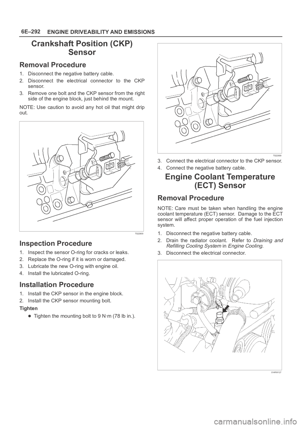
Removal Procedure
1. Disconnect the negative battery cable.
2. Disconnect the electrical connector to the CKP
sensor.
3. Remove one bolt and the CKP sensor from the right
side of the engine block, just behind the mount.
NOTE: Use caution to avoid any hot oil that might drip
out.
TS22909
Inspection Procedure
1. Inspect the sensor O-ring for cracks or leaks.
2. Replace the O-ring if it is worn or damaged.
3. Lubricate the new O-ring with engine oil.
4. Install the lubricated O-ring.
Installation Procedure
1. Install the CKP sensor in the engine block.
2. Install the CKP sensor mounting bolt.
Tighten
Tighten the mounting bolt to 9 Nꞏm (78 lb in.).
TS22909
3. Connect the electrical connector to the CKP sensor.
4. Connect the negative battery cable.
Engine Coolant Temperature
(ECT) Sensor
Removal Procedure
NOTE: Care must be taken when handling the engine
coolant temperature (ECT) sensor. Damage to the ECT
sensor will affect proper operation of the fuel injection
system.
1. Disconnect the negative battery cable.
2. Drain the radiator coolant. Refer to
Draining and
Refilling Cooling System
in Engine Cooling.
3. Disconnect the electrical connector.
014RW127
Page 4980 of 6000
6E–323 ENGINE DRIVEABILITY AND EMISSIONS
11. Connect the fuel filler fuse at the tank.
12. Connect the air breather hose at the tank.
TS23796
13. Fill the fuel tank with fuel.
14. Tighten the fuel filler cap.
15. Connect the negative battery cable.
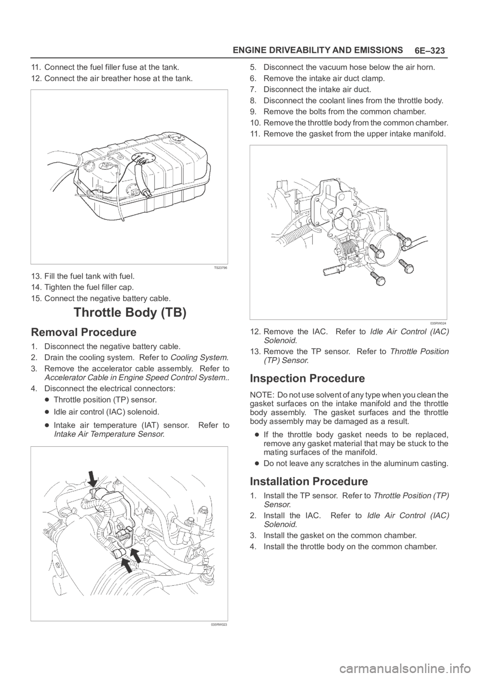
Throttle Body (TB)
Removal Procedure
1. Disconnect the negative battery cable.
2. Drain the cooling system. Refer to
Cooling System.
3. Remove the accelerator cable assembly. Refer to
Accelerator Cable in Engine Speed Control System..
4. Disconnect the electrical connectors:
Throttle position (TP) sensor.
Idle air control (IAC) solenoid.
Intake air temperature (IAT) sensor. Refer to
Intake Air Temperature Sensor.
035RW023
5. Disconnect the vacuum hose below the air horn.
6. Remove the intake air duct clamp.
7. Disconnect the intake air duct.
8. Disconnect the coolant lines from the throttle body.
9. Remove the bolts from the common chamber.
10. Remove the throttle body from the common chamber.
11. Remove the gasket from the upper intake manifold.
035RW024
12. Remove the IAC. Refer to Idle Air Control (IAC)
Solenoid
.
13. Remove the TP sensor. Refer to
Throttle Position
(TP) Sensor
.
Inspection Procedure
NOTE: Do not use solvent of any type when you clean the
gasket surfaces on the intake manifold and the throttle
body assembly. The gasket surfaces and the throttle
body assembly may be damaged as a result.
If the throttle body gasket needs to be replaced,
remove any gasket material that may be stuck to the
mating surfaces of the manifold.
Do not leave any scratches in the aluminum casting.
Installation Procedure
1. Install the TP sensor. Refer to Throttle Position (TP)
Sensor
.
2. Install the IAC. Refer to
Idle Air Control (IAC)
Solenoid
.
3. Install the gasket on the common chamber.
4. Install the throttle body on the common chamber.
Page 4981 of 6000
6E–324
ENGINE DRIVEABILITY AND EMISSIONS
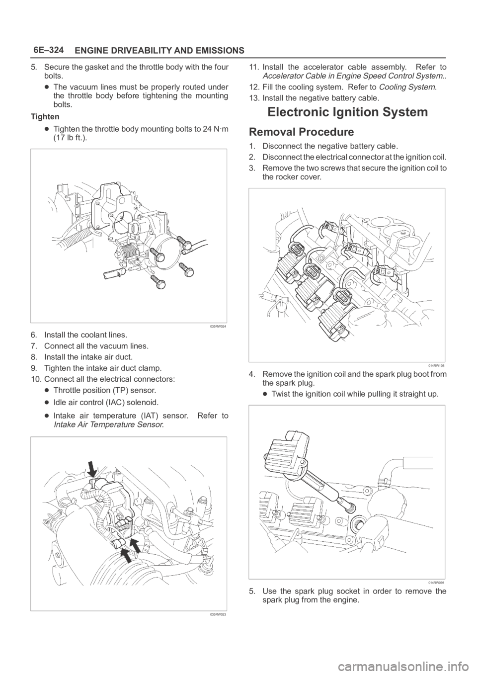
5. Secure the gasket and the throttle body with the four
bolts.
The vacuum lines must be properly routed under
the throttle body before tightening the mounting
bolts.
Tighten
Tighten the throttle body mounting bolts to 24 Nꞏm
(17 lb ft.).
035RW024
6. Install the coolant lines.
7. Connect all the vacuum lines.
8. Install the intake air duct.
9. Tighten the intake air duct clamp.
10. Connect all the electrical connectors:
Throttle position (TP) sensor.
Idle air control (IAC) solenoid.
Intake air temperature (IAT) sensor. Refer to
Intake Air Temperature Sensor.
035RW023
11. Install the accelerator cable assembly. Refer to
Accelerator Cable in Engine Speed Control System..
12. Fill the cooling system. Refer to
Cooling System.
13. Install the negative battery cable.
Electronic Ignition System
Removal Procedure
1. Disconnect the negative battery cable.
2. Disconnect the electrical connector at the ignition coil.
3. Remove the two screws that secure the ignition coil to
the rocker cover.
014RW108
4. Remove the ignition coil and the spark plug boot from
the spark plug.
Twist the ignition coil while pulling it straight up.
014RW091
5. Use the spark plug socket in order to remove the
spark plug from the engine.