Page 1482 of 6000
6G–3 ENGINE LUBRICATION
Oil Pump
Oil Pump and Associated Parts
051RW005
Legend
(1) Crankshaft Timing Pulley
(2) Crankcase with Oil Pan
(3) Oil Pipe
(4) Oil Strainer
(5) Oil Pump Assembly
(6) Plug
(7) Spring(8) Relief Valve
(9) Oil Pump Cover
(10) Driven Gear
(11) Drive Gear
(12) Oil Seal
(13) O-ring
(14) Oil Pump Body
Oil Pump and Associated Parts
1. Remove crankshaft timing pulley.
2. Remove crankcase with oil pan.
3. Remove oil pipe.
4. Remove oil strainer.5. Remove oil pump assembly.
6. Remove plug.
7. Remove spring.
8. Remove relief valve.
9. Remove oil pump cover.
10. Remove driven gear.
Page 1483 of 6000
6G–4
ENGINE LUBRICATION
11. Remove drive gear.
12. Remove oil seal.
13. Remove O-ring.
Inspection and Repair
CAUTION: Make necessary correction or parts
replacement if wear, damage or any other abnormal
conditions are found during inspection.
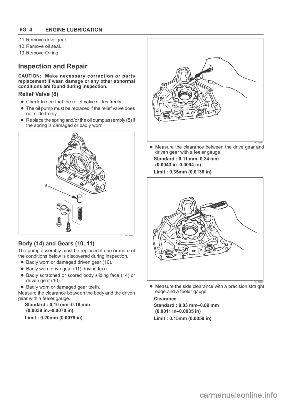
Relief Valve (8)
Check to see that the relief valve slides freely.
The oil pump must be replaced if the relief valve does
not slide freely.
Replace the spring and/or the oil pump assembly (5) if
the spring is damaged or badly worn.
051RS002
Body (14) and Gears (10, 11)
The pump assembly must be replaced if one or more of
the conditions below is discovered during inspection.
Badly worn or damaged driven gear (10).
Badly worn drive gear (11) driving face.
Badly scratched or scored body sliding face (14) or
driven gear (10).
Badly worn or damaged gear teeth.
Measure the clearance between the body and the driven
gear with a feeler gauge.
Standard : 0.10 mm–0.18 mm
(0.0039 in.–0.0070 in)
Limit : 0.20mm (0.0079 in)
051RS004
Measure the clearance between the drive gear and
driven gear with a feeler gauge.
Standard : 0.11 mm–0.24 mm
(0.0043 in–0.0094 in)
Limit : 0.35mm (0.0138 in)
051RS003
Measure the side clearance with a precision straight
edge and a feeler gauge.
Clearance
Standard : 0.03 mm–0.09 mm
(0.0011 in–0.0035 in)
Limit : 0.15mm (0.0059 in)
Page 1484 of 6000
6G–5 ENGINE LUBRICATION
051RS005
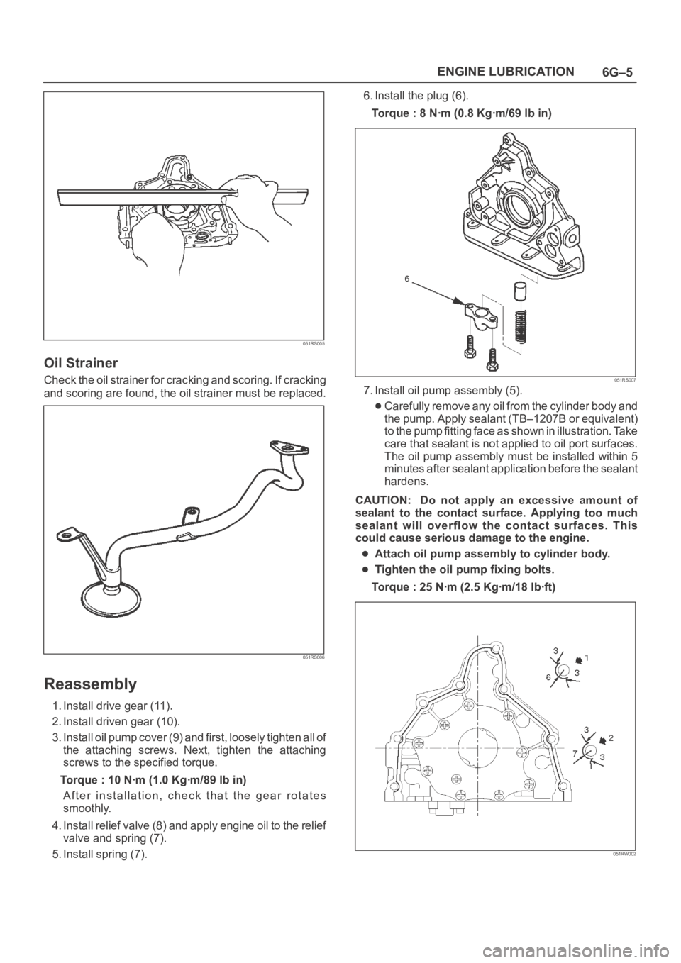
Oil Strainer
Check the oil strainer for cracking and scoring. If cracking
and scoring are found, the oil strainer must be replaced.
051RS006
Reassembly
1. Install drive gear (11).
2. Install driven gear (10).
3. Install oil pump cover (9) and first, loosely tighten all of
the attaching screws. Next, tighten the attaching
screws to the specified torque.
Torque : 10 Nꞏm (1.0 Kgꞏm/89 lb in)
After installation, check that the gear rotates
smoothly.
4. Install relief valve (8) and apply engine oil to the relief
valve and spring (7).
5. Install spring (7).6. Install the plug (6).
Torque : 8 Nꞏm (0.8 Kgꞏm/69 lb in)
051RS007
7. Install oil pump assembly (5).
Carefully remove any oil from the cylinder body and
the pump. Apply sealant (TB–1207B or equivalent)
to the pump fitting face as shown in illustration. Take
care that sealant is not applied to oil port surfaces.
The oil pump assembly must be installed within 5
minutes after sealant application before the sealant
hardens.
CAUTION: Do not apply an excessive amount of
sealant to the contact surface. Applying too much
sealant will overflow the contact surfaces. This
could cause serious damage to the engine.
Attach oil pump assembly to cylinder body.
Tighten the oil pump fixing bolts.
Torque : 25 Nꞏm (2.5 Kgꞏm/18 lbꞏft)
051RW002
Page 1806 of 6000
ENGINE MECHANICAL 6A – 73
INSTALLATION
1. Install relief valve (if it was removed).
Torque: 30 Nꞏm (3.1 kgꞏm / 22 lb ft)
2. Insert O-ring to strainer, install strainer and tighten
to specified torque.
Torque: 20 Nꞏm (2.0 kgꞏm / 14.5 lb ft)
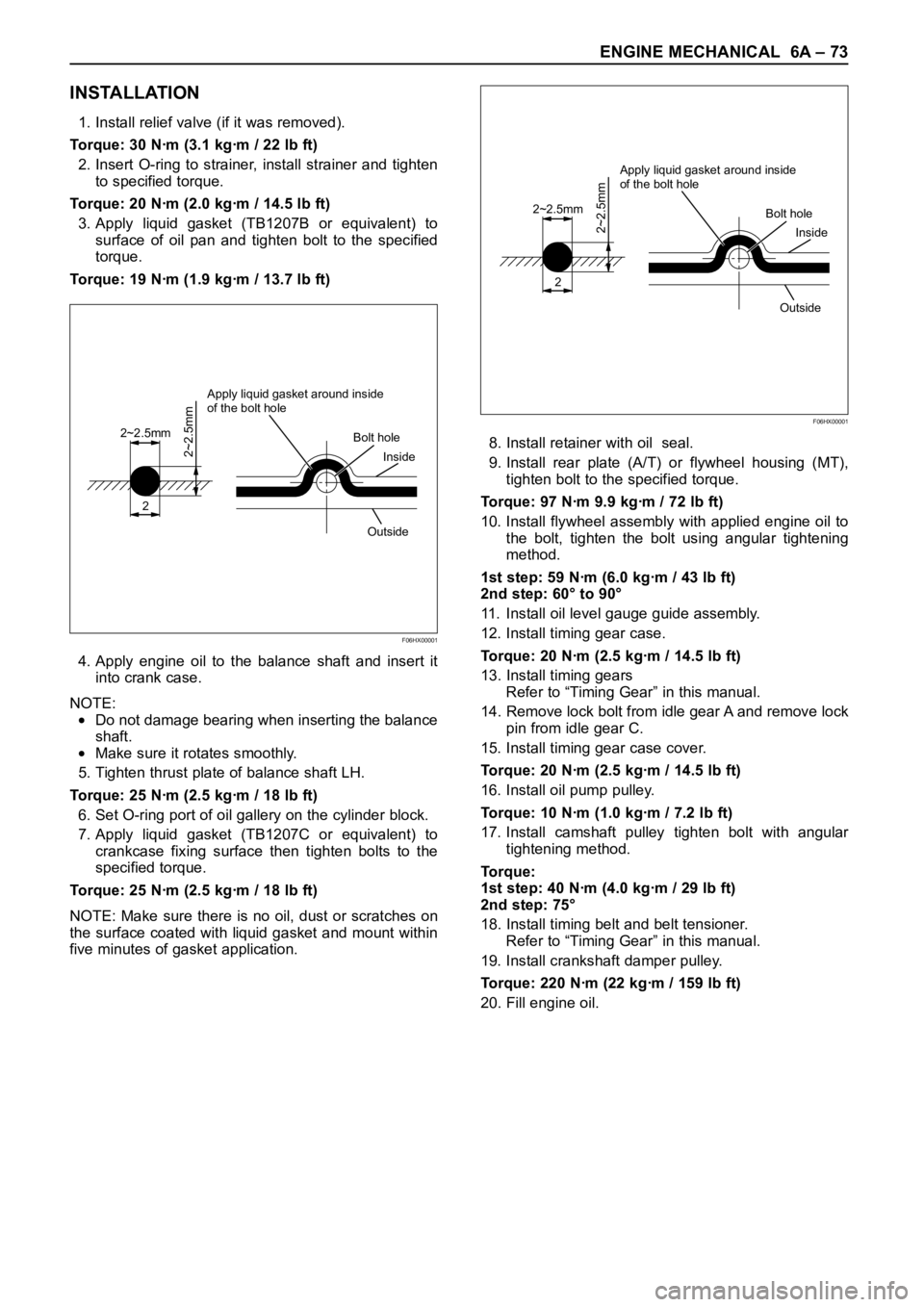
3. Apply liquid gasket (TB1207B or equivalent) to
surface of oil pan and tighten bolt to the specified
torque.
Torque: 19 Nꞏm (1.9 kgꞏm / 13.7 lb ft)
4. Apply engine oil to the balance shaft and insert it
into crank case.
NOTE:
Do not damage bearing when inserting the balance
shaft.
Make sure it rotates smoothly.
5. Tighten thrust plate of balance shaft LH.
Torque: 25 Nꞏm (2.5 kgꞏm / 18 lb ft)
6. Set O-ring port of oil gallery on the cylinder block.
7. Apply liquid gasket (TB1207C or equivalent) to
crankcase fixing surface then tighten bolts to the
specified torque.
Torque: 25 Nꞏm (2.5 kgꞏm / 18 lb ft)
NOTE: Make sure there is no oil, dust or scratches on
the surface coated with liquid gasket and mount within
five minutes of gasket application.8. Install retainer with oil seal.
9. Install rear plate (A/T) or flywheel housing (MT),
tighten bolt to the specified torque.
Torque: 97 Nꞏm 9.9 kgꞏm / 72 lb ft)
10. Install flywheel assembly with applied engine oil to
the bolt, tighten the bolt using angular tightening
method.
1st step: 59 Nꞏm (6.0 kgꞏm / 43 lb ft)
2nd step: 60° to 90°
11. Install oil level gauge guide assembly.
12. Install timing gear case.
Torque: 20 Nꞏm (2.5 kgꞏm / 14.5 lb ft)
13. Install timing gears
Refer to “Timing Gear” in this manual.
14. Remove lock bolt from idle gear A and remove lock
pin from idle gear C.
15. Install timing gear case cover.
Torque: 20 Nꞏm (2.5 kgꞏm / 14.5 lb ft)
16. Install oil pump pulley.
Torque: 10 Nꞏm (1.0 kgꞏm / 7.2 lb ft)
17. Install camshaft pulley tighten bolt with angular
tightening method.
To r q u e :
1st step: 40 Nꞏm (4.0 kgꞏm / 29 lb ft)
2nd step: 75°
18. Install timing belt and belt tensioner.
Refer to “Timing Gear” in this manual.
19. Install crankshaft damper pulley.
Torque: 220 Nꞏm (22 kgꞏm / 159 lb ft)
20. Fill engine oil.
2
2~2.5mm
2~2.5mm
Apply liquid gasket around inside
of the bolt hole
Bolt hole
Inside
Outside
F06HX00001
2
2~2.5mm
2~2.5mm
Apply liquid gasket around inside
of the bolt hole
Bolt hole
Inside
Outside
F06HX00001
Page 1827 of 6000
6A – 94 ENGINE MECHANICAL
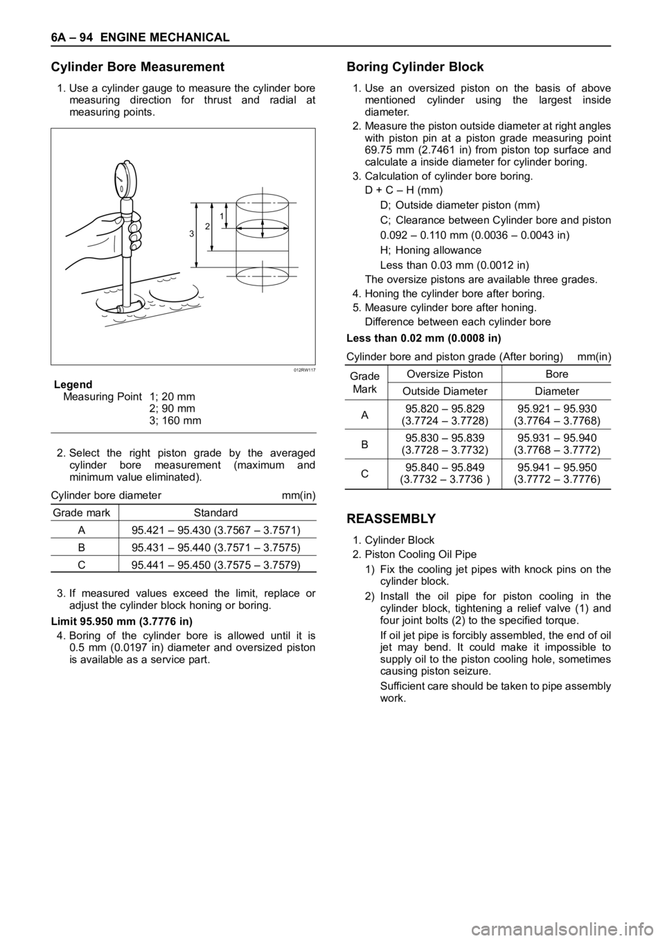
Cylinder Bore Measurement
1. Use a cylinder gauge to measure the cylinder bore
measuring direction for thrust and radial at
measuring points.
Legend
Measuring Point 1; 20 mm
2; 90 mm
3; 160 mm
2. Select the right piston grade by the averaged
cylinder bore measurement (maximum and
minimum value eliminated).
Cylinder bore diameter mm(in)
Grade mark Standard
A 95.421 – 95.430 (3.7567 – 3.7571)
B 95.431 – 95.440 (3.7571 – 3.7575)
C 95.441 – 95.450 (3.7575 – 3.7579)
3. If measured values exceed the limit, replace or
adjust the cylinder block honing or boring.
Limit 95.950 mm (3.7776 in)
4. Boring of the cylinder bore is allowed until it is
0.5 mm (0.0197 in) diameter and oversized piston
is available as a service part.
Boring Cylinder Block
1. Use an oversized piston on the basis of above
mentioned cylinder using the largest inside
diameter.
2. Measure the piston outside diameter at right angles
with piston pin at a piston grade measuring point
69.75 mm (2.7461 in) from piston top surface and
calculate a inside diameter for cylinder boring.
3. Calculation of cylinder bore boring.
D + C – H (mm)
D; Outside diameter piston (mm)
C; Clearance between Cylinder bore and piston
0.092 – 0.110 mm (0.0036 – 0.0043 in)
H; Honing allowance
Less than 0.03 mm (0.0012 in)
The oversize pistons are available three grades.
4. Honing the cylinder bore after boring.
5. Measure cylinder bore after honing.
Difference between each cylinder bore
Less than 0.02 mm (0.0008 in)
Cylinder bore and piston grade (After boring) mm(in)
GradeOversize Piston Bore
Mark
Outside Diameter Diameter
A95.820 – 95.829 95.921 – 95.930
(3.7724 – 3.7728) (3.7764 – 3.7768)
B95.830 – 95.839 95.931 – 95.940
(3.7728 – 3.7732) (3.7768 – 3.7772)
C95.840 – 95.849 95.941 – 95.950
(3.7732 – 3.7736 ) (3.7772 – 3.7776)
REASSEMBLY
1. Cylinder Block
2. Piston Cooling Oil Pipe
1) Fix the cooling jet pipes with knock pins on the
cylinder block.
2) Install the oil pipe for piston cooling in the
cylinder block, tightening a relief valve (1) and
four joint bolts (2) to the specified torque.
If oil jet pipe is forcibly assembled, the end of oil
jet may bend. It could make it impossible to
supply oil to the piston cooling hole, sometimes
causing piston seizure.
Sufficient care should be taken to pipe assembly
work.
321
012RW117
Page 1828 of 6000
ENGINE MECHANICAL 6A – 95
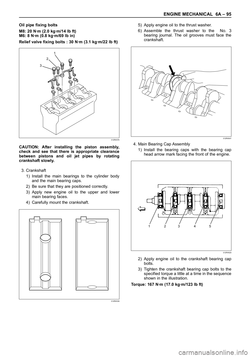
Oil pipe fixing bolts
M8: 20 Nꞏm (2.0 kgꞏm/14 lb ft)
M6: 8 Nꞏm (0.8 kgꞏm/69 lb in)
Relief valve fixing bolts : 30 Nꞏm (3.1 kgꞏm/22 lb ft)
CAUTION: After installing the piston assembly,
check and see that there is appropriate clearance
between pistons and oil jet pipes by rotating
crankshaft slowly.
3. Crankshaft
1) Install the main bearings to the cylinder body
and the main bearing caps.
2) Be sure that they are positioned correctly.
3) Apply new engine oil to the upper and lower
main bearing faces.
4) Carefully mount the crankshaft.5) Apply engine oil to the thrust washer.
6) Assemble the thrust washer to the No. 3
bearing journal. The oil grooves must face the
crankshaft.
4. Main Bearing Cap Assembly
1) Install the bearing caps with the bearing cap
head arrow mark facing the front of the engine.
2) Apply engine oil to the crankshaft bearing cap
bolts.
3) Tighten the crankshaft bearing cap bolts to the
specified torque a little at a time in the sequence
shown in the illustration.
Torque: 167 Nꞏm (17.0 kgꞏm/123 lb ft)
321
012RW076
012RW038
012RW047
12345
012RW025
Page 1849 of 6000
6C – 4 ENGINE FUEL
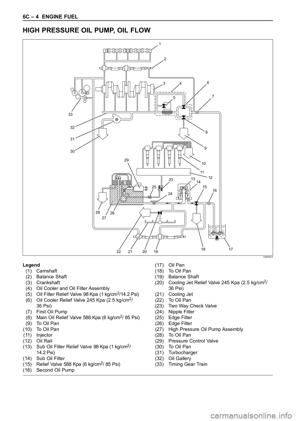
HIGH PRESSURE OIL PUMP, OIL FLOW
P
33
32
31
30
1
2
3
4
56
8
97
10
11
12
13
14 23 29
25
28
27262415
16
17 18
19 20 21 22
Legend
(1) Camshaft
(2) Balance Shaft
(3) Crankshaft
(4) Oil Cooler and Oil Filter Assembly
(5) Oil Filter Relief Valve 98 Kpa (1 kg/cm
2/14.2 Psi)
(6) Oil Cooler Relief Valve 245 Kpa (2.5 kg/cm2/
36 Psi)
(7) First Oil Pump
(8) Main Oil Relief Valve 588 Kpa (6 kg/cm
2/ 85 Psi)
(9) To Oil Pan
(10) To Oil Pan
(11) Injector
(12) Oil Rail
(13) Sub Oil Filter Relief Valve 98 Kpa (1 kg/cm
2/
14.2 Psi)
(14) Sub Oil Filter
(15) Relief Valve 588 Kpa (6 kg/cm
2/ 85 Psi)
(16) Second Oil Pump(17) Oil Pan
(18) To Oil Pan
(19) Balance Shaft
(20) Cooling Jet Relief Valve 245 Kpa (2.5 kg/cm
2/
36 Psi)
(21) Cooling Jet
(22) To Oil Pan
(23) Two Way Check Valve
(24) Nipple Filter
(25) Edge Filter
(26) Edge Filter
(27) High Pressure Oil Pump Assembly
(28) To Oil Pan
(29) Pressure Control Valve
(30) To Oil Pan
(31) Turbocharger
(32) Oil Gallery
(33) Timing Gear Train
040RW018
Page 2133 of 6000
6G – 2 ENGINE LUBRICATION
GENERAL DESCRIPTION
LUBRICATION CHART
P
33
32
31
30
1
2
3
4
56
8
97
10
11
12
13
14 23 29
25
28
27262415
16
17 18
19 20 21 22
Legend
(1) Camshaft
(2) Balance Shaft
(3) Crankshaft
(4) Oil Cooler and Oil Filter Assembly
(5) Oil Filter Relief Valve 98 Kpa (1 kg/cm
2/14.2 Psi)
(6) Oil Cooler Relief Valve 245 Kpa (2.5 kg/cm2/
36 Psi)
(7) First Oil Pump
(8) Main Oil Relief Valve 588 Kpa (6 kg/cm
2/ 85 Psi)
(9) To Oil Pan
(10) To Oil Pan
(11) Injector
(12) Oil Rail(13) Sub Oil Filter Relief Valve 98 Kpa (1 kg/cm
2/
14.2 Psi)
(14) Sub Oil Filter
(15) Relief Valve 588 Kpa (6 kg/cm
2/ 85 Psi)
(16) Second Oil Pump
(17) Oil Pan
(18) To Oil Pan
(19) Balance Shaft
(20) Cooling Jet Relief Valve 245 Kpa (2.5 kg/cm
2/
36 Psi)
(21) Cooling Jet
(22) To Oil Pan
(23) Two Way Check Valve
(24) Nipple Filter
040RW018