Page 505 of 6000

4A2B–2DIFFERENTIAL (REAR 244mm)
General Description
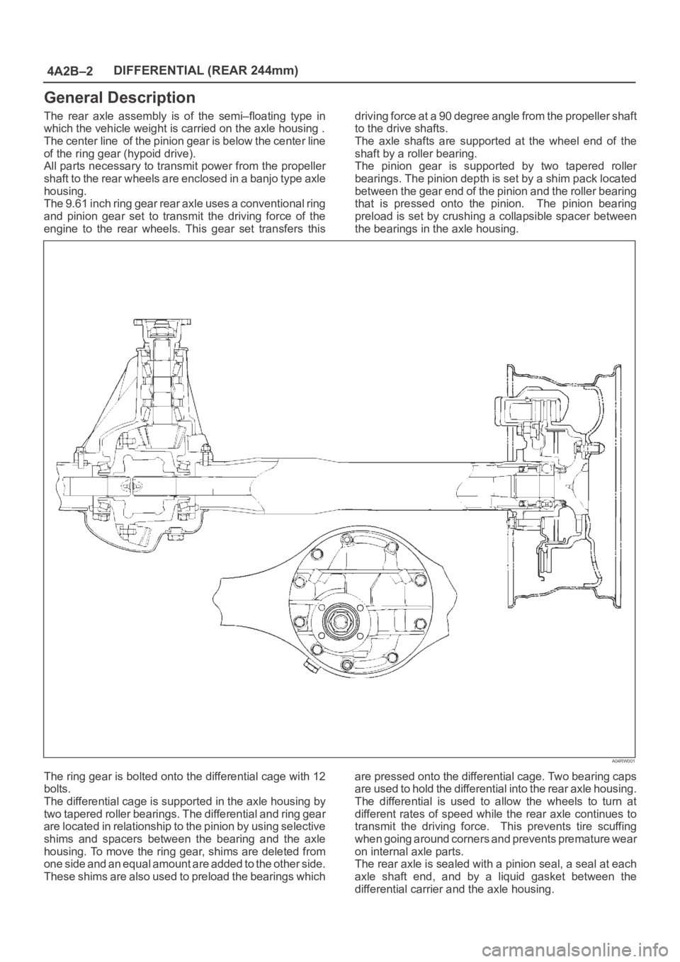
The rear axle assembly is of the semi–floating type in
which the vehicle weight is carried on the axle housing .
The center line of the pinion gear is below the center line
of the ring gear (hypoid drive).
All parts necessary to transmit power from the propeller
shaft to the rear wheels are enclosed in a banjo type axle
housing.
The 9.61 inch ring gear rear axle uses a conventional ring
and pinion gear set to transmit the driving force of the
engine to the rear wheels. This gear set transfers thisdriving force at a 90 degree angle from the propeller shaft
to the drive shafts.
The axle shafts are supported at the wheel end of the
shaft by a roller bearing.
The pinion gear is supported by two tapered roller
bearings. The pinion depth is set by a shim pack located
between the gear end of the pinion and the roller bearing
that is pressed onto the pinion. The pinion bearing
preload is set by crushing a collapsible spacer between
the bearings in the axle housing.
A04RW001
The ring gear is bolted onto the differential cage with 12
bolts.
The differential cage is supported in the axle housing by
two tapered roller bearings. The differential and ring gear
are located in relationship to the pinion by using selective
shims and spacers between the bearing and the axle
housing. To move the ring gear, shims are deleted from
one side and an equal amount are added to the other side.
These shims are also used to preload the bearings whichare pressed onto the differential cage. Two bearing caps
are used to hold the differential into the rear axle housing.
The differential is used to allow the wheels to turn at
different rates of speed while the rear axle continues to
transmit the driving force. This prevents tire scuffing
when going around corners and prevents premature wear
on internal axle parts.
The rear axle is sealed with a pinion seal, a seal at each
axle shaft end, and by a liquid gasket between the
differential carrier and the axle housing.
Page 546 of 6000
4B1–13 DRIVE LINE CONTROL SYSTEM (SHIFT ON THE FLY)
Parts Location (LHD / Gasoline Engine Model)
D08RW854
Legend
(1) I–12
(2) I–9
(3) H–7, H–8, H–24, H–25
(4) Fuse Box
(5) C–16
(6) C–94
(7) H–5
(8) M–11, M–12(9) M–22
(10) M–23
(11) M–24
(12) H–10
(13) M–26
(14) Relay & Fuse Box
(15) H–12, H–16
(16) E–30
Page 548 of 6000
4B1–15 DRIVE LINE CONTROL SYSTEM (SHIFT ON THE FLY)
Parts Location (RHD / Gasoline Engine Model)
D08RW853
Legend
(1) I–9
(2) I–12
(3) H–7, H–9
(4) C–16
(5) H–5
(6) C–94
(7) M–26
(8) M–11, M–12(9) M–22
(10) M–23
(11) M–24
(12) H–10
(13) H–12
(14) Relay & Fuse Box
(15) E–30
(16) H–15, H–16, H–25, H–26, H–27
(17) Fuse Box
Page 551 of 6000
4B1–18
DRIVE LINE CONTROL SYSTEM (SHIFT ON THE FLY)
Wiring Diagram (LHD / Gasoline Engine Model)
D08RW843
Page 554 of 6000
4B1–21 DRIVE LINE CONTROL SYSTEM (SHIFT ON THE FLY)
Wiring Diagram (RHD / Gasoline Engine Model)
D08RW638
Page 578 of 6000
4B2–7 DRIVE LINE CONTROL SYSTEM (TOD)
Check Lamp
Inform the following items.
Bulb check
Fail (fail alarm)
Trouble code
Diesel/gasoline MAP
821RW078
TOD ECU
This control unit is mounted to the front right hand seat via
a special bracket.
F07RW029
Page 582 of 6000

4B2–11 DRIVE LINE CONTROL SYSTEM (TOD)
The CHECK lamp also has the following functions.
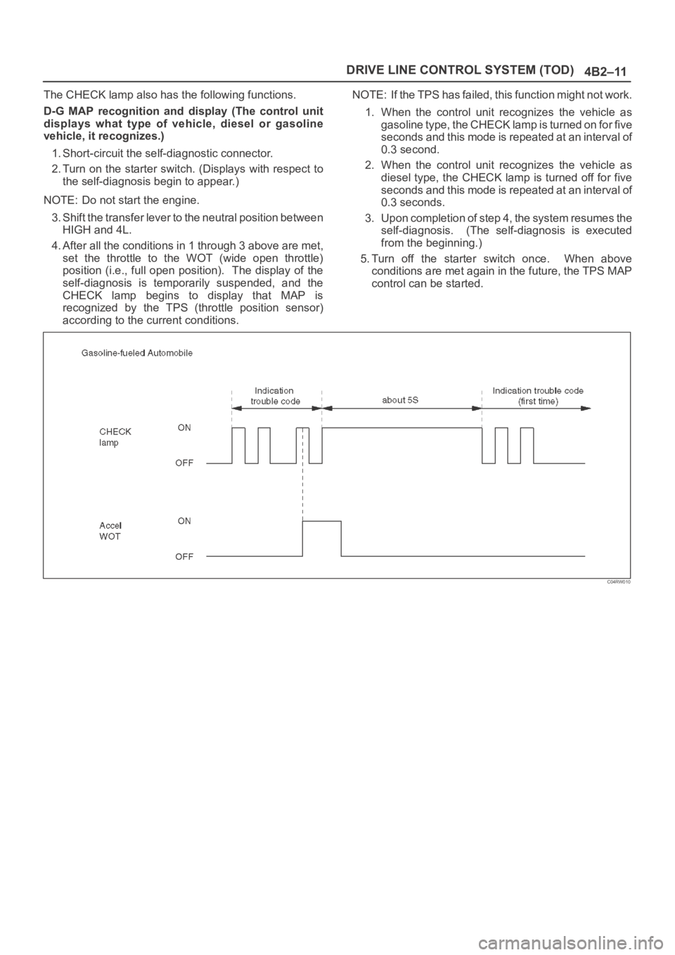
D-G MAP recognition and display (The control unit
displays what type of vehicle, diesel or gasoline
vehicle, it recognizes.)
1. Short-circuit the self-diagnostic connector.
2. Turn on the starter switch. (Displays with respect to
the self-diagnosis begin to appear.)
NOTE: Do not start the engine.
3. Shift the transfer lever to the neutral position between
HIGH and 4L.
4. After all the conditions in 1 through 3 above are met,
set the throttle to the WOT (wide open throttle)
position (i.e., full open position). The display of the
self-diagnosis is temporarily suspended, and the
CHECK lamp begins to display that MAP is
recognized by the TPS (throttle position sensor)
according to the current conditions.NOTE: If the TPS has failed, this function might not work.
1. When the control unit recognizes the vehicle as
gasoline type, the CHECK lamp is turned on for five
seconds and this mode is repeated at an interval of
0.3 second.
2. When the control unit recognizes the vehicle as
diesel type, the CHECK lamp is turned off for five
seconds and this mode is repeated at an interval of
0.3 seconds.
3. Upon completion of step 4, the system resumes the
self-diagnosis. (The self-diagnosis is executed
from the beginning.)
5. Turn off the starter switch once. When above
conditions are met again in the future, the TPS MAP
control can be started.
C04RW010
Page 597 of 6000

DRIVE LINE CONTROL SYSTEM (TOD) 4B2–26
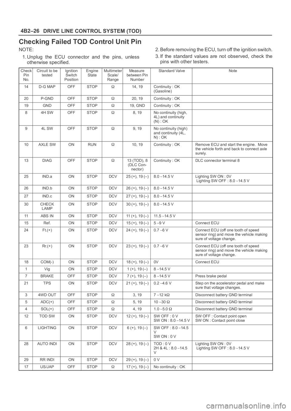
Checking Failed TOD Control Unit Pin
NOTE:
1. Unplug the ECU connector and the pins, unless
otherwise specified.2. Before removing the ECU, turn off the ignition switch.
3. If the standard values are not observed, check the
pins with other testers.
Check
Pin
No.Circuit to be
testedIgnition
Switch
PositionEngine
StateMultimeter
Scale/
RangeMeasure
between Pin
NumberStandard ValveNote
14D-G MAPOFFSTOP14, 19Continuity : OK
(Gasoline)
20P-GNDOFFSTOP20, 19Continuity : OK
19GNDOFFSTOP19, GNDContinuity : OK
84H SWOFFSTOP8, 19No continuity (high,
4L) and continuity
(N) : OK
94L SWOFFSTOP9, 19No continuity (high)
and continuity (4L,
N) : OK
10AXLE SWONRUN10, 19Continuity : OKRemove ECU and start the engine. Move
the vehicle forth and back to connect axle
surely.
13DIAGOFFSTOP13 (TOD), 8
(DLC Con-
nector)Continuity : OKDLC connector terminal 8
25IND.aONSTOPDCV25 (+), 19 (–)8.0 14.5 VLighting SW ON : 0V
Lighting SW OFF : 8.0 14.5 V
26IND.bONSTOPDCV26 (+), 19 (–)8.0 14.5 V
27IND.cONSTOPDCV27 (+), 19 (–)8.0 14.5 V
30CHECK
LAMPONSTOPDCV30 (+), 19 (–)8.0 14.5 V
11ABS INONSTOPDCV11 (+), 19 (–)11 . 5 14.5 V
15Ref.ONSTOPDCV15 (+), 19 (–)5 9 VConnect ECU
24Ft.(+)ONSTOPDCV24 (+), 19 (–)0.7 6 VConnect ECU (off one tooth of speed
sensor ring) and move the vehicle making
sure of voltage change.
23Rr.(+)ONSTOPDCV23 (+), 19 (–)0.7 6 VConnect ECU (off one tooth of speed
sensor ring) and move the vehicle making
sure of voltage change.
18COM(-)ONSTOPDCV18 (+), 19 (–)0VConnect ECU
1VigONSTOPDCV1 (+), 19 (–)8 14.5 V
7BRAKEOFFSTOPDCV7 (+), 19 (–)8 14.5 VPress brake pedal
21TPSONSTOPDCV21 (+), 19 (–)0.2 4.6 VStep on the accelerator pedal and make
sure that voltage changes.
34WD OUTOFFSTOP3, 197 12 kDisconnect battery GND terminal
5ADC(+)OFFSTOP5, 1910 30 Disconnect battery GND terminal
4SOL(+)OFFSTOP4, 191.0 5.0 Disconnect battery GND terminal
12TOD SWONSTOPDCV12 (+), 19 (–)SW OFF : 0 V
SW ON : 8.0 14.5 VSW OFF : Contact point open
SW ON : Contact point close
6LIGHTINGONSTOPDCV6 (+), 19 (–)SW OFF : 8.0 14.5
V
SW ON : 0 V
28AUTO INDIONSTOPDCV28 (+), 19 (–)TOD : 0 V
2H & 4L : 8.0 14.5
VLighting SW ON : 0V
Lighting SW OFF : 8.0 14.5 V
29RR INDIONSTOPDCV29 (+), 19 (–)0 V
17US/JAPOFFSTOP17 (+), 19 (–)No continuity : OK