Page 1043 of 6000

6A–87
ENGINE MECHANICAL
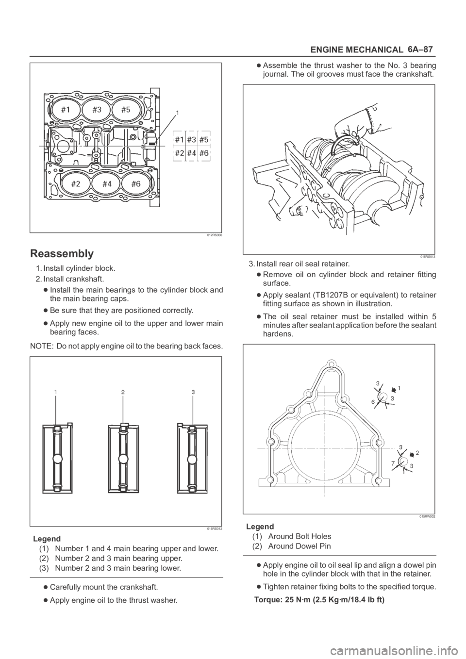
012RS006
Reassembly
1. Install cylinder block.
2. Install crankshaft.
Install the main bearings to the cylinder block and
the main bearing caps.
Be sure that they are positioned correctly.
Apply new engine oil to the upper and lower main
bearing faces.
NOTE: Do not apply engine oil to the bearing back faces.
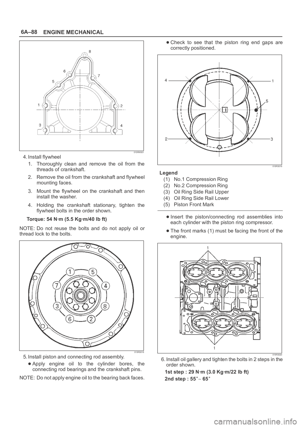
015RS012
Legend
(1) Number 1 and 4 main bearing upper and lower.
(2) Number 2 and 3 main bearing upper.
(3) Number 2 and 3 main bearing lower.
Carefully mount the crankshaft.
Apply engine oil to the thrust washer.
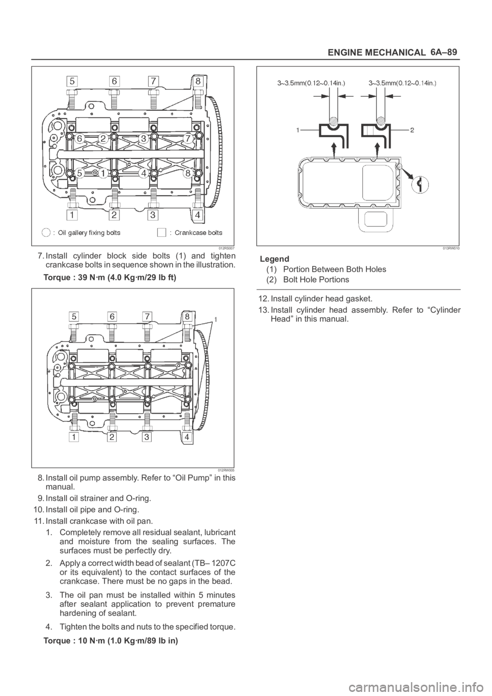
Assemble the thrust washer to the No. 3 bearing
journal. The oil grooves must face the crankshaft.
015RS013
3. Install rear oil seal retainer.
Remove oil on cylinder block and retainer fitting
surface.
Apply sealant (TB1207B or equivalent) to retainer
fitting surface as shown in illustration.
The oil seal retainer must be installed within 5
minutes after sealant application before the sealant
hardens.
015RW002
Legend
(1) Around Bolt Holes
(2) Around Dowel Pin
Apply engine oil to oil seal lip and align a dowel pin
hole in the cylinder block with that in the retainer.
Tighten retainer fixing bolts to the specified torque.
Torque: 25 Nꞏm (2.5 Kgꞏm/18.4 lb ft)
Page 1044 of 6000

6A–88
ENGINE MECHANICAL
015RW001
4. Install flywheel
1. Thoroughly clean and remove the oil from the
threads of crankshaft.
2. Remove the oil from the crankshaft and flywheel
mounting faces.
3. Mount the flywheel on the crankshaft and then
install the washer.
4. Holding the crankshaft stationary, tighten the
flywheel bolts in the order shown.
Torque: 54 Nꞏm (5.5 Kgꞏm/40 lb ft)
NOTE: Do not reuse the bolts and do not apply oil or
thread lock to the bolts.
015RS018
5. Install piston and connecting rod assembly.
Apply engine oil to the cylinder bores, the
connecting rod bearings and the crankshaft pins.
NOTE: Do not apply engine oil to the bearing back faces.
Check to see that the piston ring end gaps are
correctly positioned.
015RS019
Legend
(1) No.1 Compression Ring
(2) No.2 Compression Ring
(3) Oil Ring Side Rail Upper
(4) Oil Ring Side Rail Lower
(5) Piston Front Mark
Insert the piston/connecting rod assemblies into
each cylinder with the piston ring compressor.
The front marks (1) must be facing the front of the
engine.
015RS020
6. Install oil gallery and tighten the bolts in 2 steps in the
order shown.
1st step : 29 Nꞏm (3.0 Kgꞏm/22 lb ft)
2nd step : 55
65
Page 1045 of 6000

6A–89
ENGINE MECHANICAL
012RS007
7. Install cylinder block side bolts (1) and tighten
crankcase bolts in sequence shown in the illustration.
Torque : 39 Nꞏm (4.0 Kgꞏm/29 lb ft)
012RW005
8. Install oil pump assembly. Refer to “Oil Pump” in this
manual.
9. Install oil strainer and O-ring.
10. Install oil pipe and O-ring.
11. Install crankcase with oil pan.
1. Completely remove all residual sealant, lubricant
and moisture from the sealing surfaces. The
surfaces must be perfectly dry.
2. Apply a correct width bead of sealant (TB– 1207C
or its equivalent) to the contact surfaces of the
crankcase. There must be no gaps in the bead.
3. The oil pan must be installed within 5 minutes
after sealant application to prevent premature
hardening of sealant.
4. Tighten the bolts and nuts to the specified torque.
Torque : 10 Nꞏm (1.0 Kgꞏm/89 lb in)
013RW010
Legend
(1) Portion Between Both Holes
(2) Bolt Hole Portions
12. Install cylinder head gasket.
13. Install cylinder head assembly. Refer to “Cylinder
Head” in this manual.
Page 1046 of 6000
6A–90
ENGINE MECHANICAL
Main Data and Specification
General Specification
ItemSpecificationsItem6VD16VE1
Engine type, number of cylinders and arrangementWater cooled, four cycle V6
Form of combustion chamberPent roof type
Valve mechanism4-Cams, 4-Valves, DOHC Gear & Belt Drive
Cylinder liner typeCasted in cylinder drive
Total piston displacement3165 cc3494 cc
Cylinder bore x stroke93.4mm x 77.0mm93.4mm x 85.0mm
(3.6772 in x 3.0315 in)(3.6772 in x 3.3465 in)
Compression ratio9.1 : 1
Compression pressure at 300rpm14.0 Kg/cm
Engine idling speed rpmNon adjustable (750)
Valve clearanceIntake: 0.28 mm (0.11 in)
Exhaust: 0.30mm (0.12in)
Oil capacity5.3 liters
Ignition timingNon adjustableNon adjustable
16 BTDC at idle rpm)(20 BTDC at idle rpm)
Spark plugK16PR–P11, PK16PR11, RC10PYP4
Plug gap1.0 mm–1.1 mm(0.0394 in – 0.0433 in)
Page 1047 of 6000
6A–91
ENGINE MECHANICAL
Torque Specifications
Ignition coil, Spark plug, Crankshaft angle sensor and Under cover
Nꞏm (Kgꞏm/Ib ft)
E06RW038
Page 1048 of 6000
6A–92
ENGINE MECHANICAL
Cylinder head cover, Cylinder head, Camshaft bracket, Common chamber, EGR valve and EGR pipe
Nꞏm (Kgꞏm/Ib ft)
E06RW043
Page 1049 of 6000
6A–93
ENGINE MECHANICAL
Crankshaft main bearing, Flywheel, Crankcase, Oil pan, Timing belt tensioner, Timing pulley, Timing belt
cover, Oil pump, Oil gallery, Oil strainer and Water pump
Nꞏm (Kgꞏm/Ib ft)
E06RW039
Page 1050 of 6000
6A–94
ENGINE MECHANICAL
Connecting rod and Water pump
Nꞏm (Kgꞏm/Ib ft)
E06RW042