1998 OPEL FRONTERA check oil
[x] Cancel search: check oilPage 1400 of 6000
6E–283 ENGINE DRIVEABILITY AND EMISSIONS
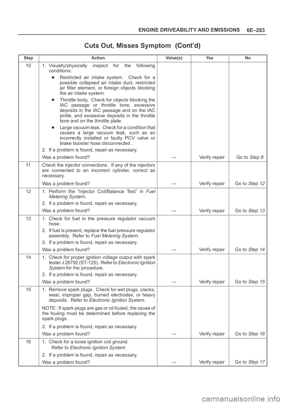
Cuts Out, Misses Symptom
StepNo Ye s Va l u e ( s ) Action
101. Visually/physically inspect for the following
conditions:
Restricted air intake system. Check for a
possible collapsed air intake duct, restricted
air filter element, or foreign objects blocking
the air intake system.
Throttle body. Check for objects blocking the
IAC passage or throttle bore, excessive
deposits in the IAC passage and on the IAC
pintle, and excessive deposits in the throttle
bore and on the throttle plate.
Large vacuum leak. Check for a condition that
causes a large vacuum leak, such as an
incorrectly installed or faulty PCV valve or
brake booster hose disconnected .
2. If a problem is found, repair as necessary.
Was a problem found?
—Verify repairGo to Step 8
11Check the injector connections. If any of the injectors
are connected to an incorrect cylinder, correct as
necessary.
Was a problem found?
—Verify repairGo to Step 12
121. Perform the “Injector Coil/Balance Test” in Fuel
Metering System
.
2. If a problem is found, repair as necessary.
Was a problem found?
—Verify repairGo to Step 13
131. Check for fuel in the pressure regulator vacuum
hose.
2. If fuel is present, replace the fuel pressure regulator
assembly. Refer to
Fuel Metering System.
3. If a problem is found, repair as necessary.
Was a problem found?
—Verify repairGo to Step 14
141. Check for proper ignition voltage output with spark
tester J 26792 (ST-125). Refer to
Electronic Ignition
System
for the procedure.
2. If a problem is found, repair as necessary.
Was a problem found?
—Verify repairGo to Step 15
151. Remove spark plugs. Check for wet plugs, cracks,
wear, improper gap, burned electrodes, or heavy
deposits. Refer to
Electronic Ignition System.
NOTE: If spark plugs are gas or oil fouled, the cause of
the fouling must be determined before replacing the
spark plugs.
2. If a problem is found, repair as necessary.
Was a problem found?
—Verify repairGo to Step 16
161. Check for a loose ignition coil ground.
Refer to
Electronic Ignition System.
2. If a problem is found, repair as necessary.
Was a problem found?
—Verify repairGo to Step 17
Page 1401 of 6000
6E–284
ENGINE DRIVEABILITY AND EMISSIONS
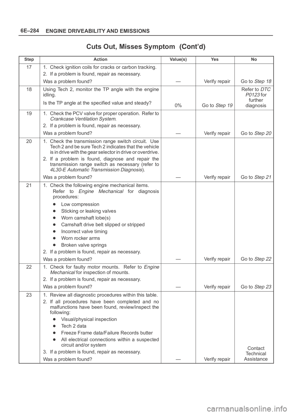
Cuts Out, Misses Symptom
StepNo Ye s Va l u e ( s ) Action
171. Check ignition coils for cracks or carbon tracking.
2. If a problem is found, repair as necessary.
Was a problem found?
—Verify repairGo to Step 18
18Using Tech 2, monitor the TP angle with the engine
idling.
Is the TP angle at the specified value and steady?
0%Go to Step 19
Refer to DTC
P0123
for
further
diagnosis
191. Check the PCV valve for proper operation. Refer to
Crankcase Ventilation System.
2. If a problem is found, repair as necessary.
Was a problem found?
—Verify repairGo to Step 20
201. Check the transmission range switch circuit. Use
Tech 2 and be sure Tech 2 indicates that the vehicle
is in drive with the gear selector in drive or overdrive.
2. If a problem is found, diagnose and repair the
transmission range switch as necessary (refer to
4L30-E Automatic Transmission Diagnosis).
Was a problem found?
—Verify repairGo to Step 21
211. Check the following engine mechanical items.
Refer to
Engine Mechanical for diagnosis
procedures:
Low compression
Sticking or leaking valves
Worn camshaft lobe(s)
Camshaft drive belt slipped or stripped
Incorrect valve timing
Worn rocker arms
Broken valve springs
2. If a problem is found, repair as necessary.
Was a problem found?
—Verify repairGo to Step 22
221. Check for faulty motor mounts. Refer to Engine
Mechanical
for inspection of mounts.
2. If a problem is found, repair as necessary.
Was a problem found?
—Verify repairGo to Step 23
231. Review all diagnostic procedures within this table.
2. If all procedures have been completed and no
malfunctions have been found, review/inspect the
following:
Visual/physical inspection
Te c h 2 d a t a
Freeze Frame data/Failure Records butter
All electrical connections within a suspected
circuit and/or system
3. If a problem is found, repair as necessary.
Was a problem found?
—Verify repair
Contact
Te c h n i c a l
Assistance
Page 1403 of 6000
6E–286
ENGINE DRIVEABILITY AND EMISSIONS
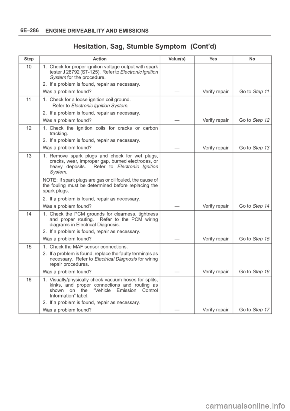
Hesitation, Sag, Stumble Symptom
StepNo Ye s Va l u e ( s ) Action
101. Check for proper ignition voltage output with spark
tester J 26792 (ST-125). Refer to
Electronic Ignition
System
for the procedure.
2. If a problem is found, repair as necessary.
Was a problem found?
—Verify repairGo to Step 11
111. Check for a loose ignition coil ground.
Refer to
Electronic Ignition System.
2. If a problem is found, repair as necessary.
Was a problem found?
—Verify repairGo to Step 12
121. Check the ignition coils for cracks or carbon
tracking.
2. If a problem is found, repair as necessary.
Was a problem found?
—Verify repairGo to Step 13
131. Remove spark plugs and check for wet plugs,
cracks, wear, improper gap, burned electrodes, or
heavy deposits. Refer to
Electronic Ignition
System
.
NOTE: If spark plugs are gas or oil fouled, the cause of
the fouling must be determined before replacing the
spark plugs.
2. If a problem is found, repair as necessary.
Was a problem found?
—Verify repairGo to Step 14
141. Check the PCM grounds for clearness, tightness
and proper routing. Refer to the PCM wiring
diagrams in Electrical Diagnosis.
2. If a problem is found, repair as necessary.
Was a problem found?
—Verify repairGo to Step 15
151. Check the MAF sensor connections.
2. If a problem is found, replace the faulty terminals as
necessary. Refer to
Electrical Diagnosis for wiring
repair procedures.
Was a problem found?
—Verify repairGo to Step 16
161. Visually/physically check vacuum hoses for splits,
kinks, and proper connections and routing as
shown on the “Vehicle Emission Control
Information” label.
2. If a problem is found, repair as necessary.
Was a problem found?
—Verify repairGo to Step 17
Page 1420 of 6000
6E–303 ENGINE DRIVEABILITY AND EMISSIONS
4. Check the transfer case oil level. Add fluid if
necessary.
5. Connect the negative battery cable.
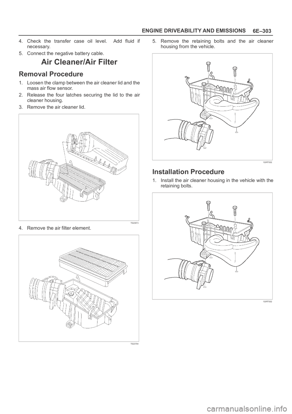
Air Cleaner/Air Filter
Removal Procedure
1. Loosen the clamp between the air cleaner lid and the
mass air flow sensor.
2. Release the four latches securing the lid to the air
cleaner housing.
3. Remove the air cleaner lid.
TS23973
4. Remove the air filter element.
TS23794
5. Remove the retaining bolts and the air cleaner
housing from the vehicle.
130RT002
Installation Procedure
1. Install the air cleaner housing in the vehicle with the
retaining bolts.
130RT002
Page 1431 of 6000
6E–314
ENGINE DRIVEABILITY AND EMISSIONS
3. Connect the wiring connector to the fuel gauge unit.
TS23771
4. Fill the fuel tank with fuel.
Tighten the fuel filler cap.
Check for leaks at the fuel gauge unit gasket.
5. Connect the negative battery cable.
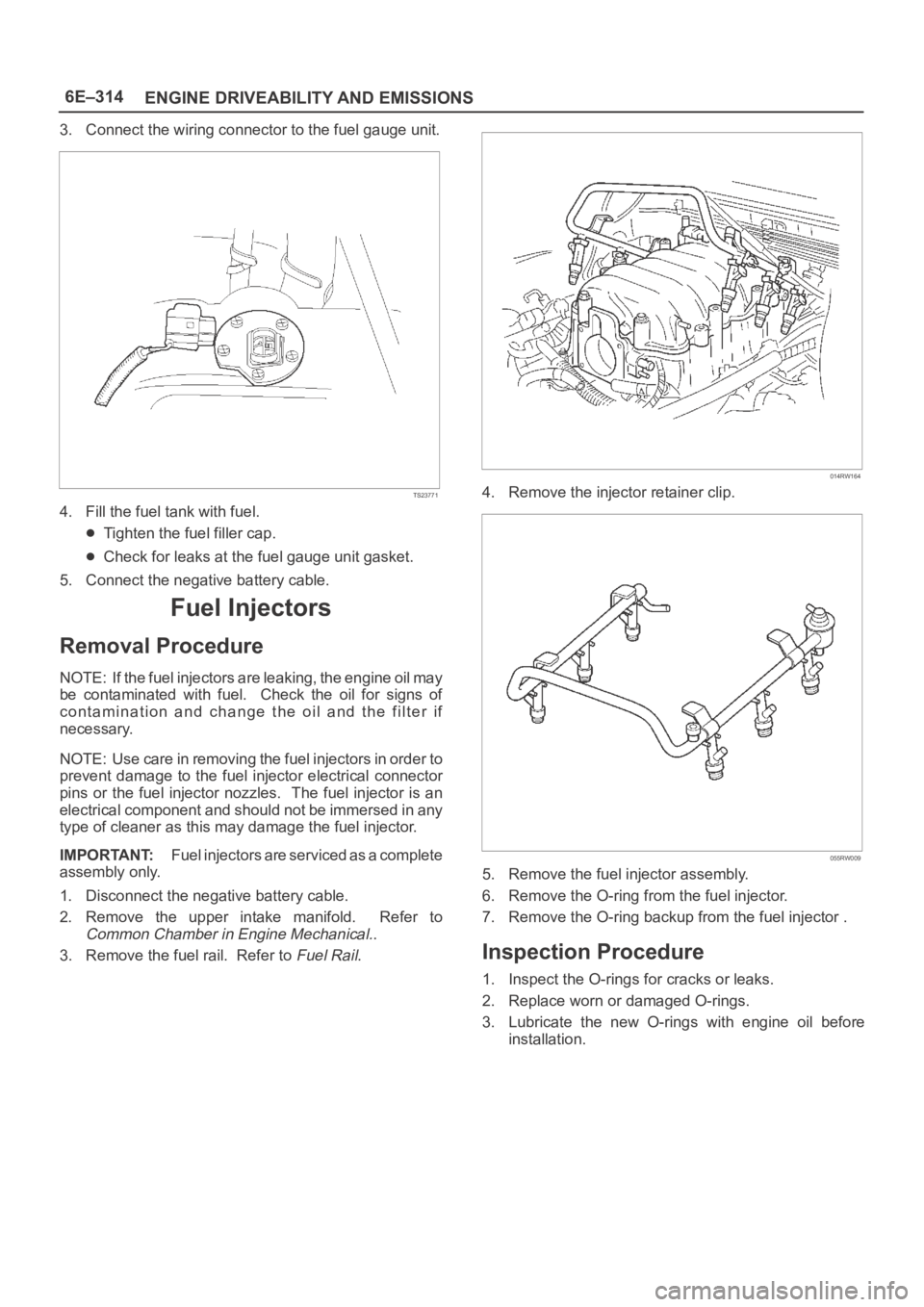
Fuel Injectors
Removal Procedure
NOTE: If the fuel injectors are leaking, the engine oil may
be contaminated with fuel. Check the oil for signs of
contamination and change the oil and the filter if
necessary.
NOTE: Use care in removing the fuel injectors in order to
prevent damage to the fuel injector electrical connector
pins or the fuel injector nozzles. The fuel injector is an
electrical component and should not be immersed in any
type of cleaner as this may damage the fuel injector.
IMPORTANT:Fuel injectors are serviced as a complete
assembly only.
1. Disconnect the negative battery cable.
2. Remove the upper intake manifold. Refer to
Common Chamber in Engine Mechanical..
3. Remove the fuel rail. Refer to
Fuel Rail.
014RW164
4. Remove the injector retainer clip.
055RW009
5. Remove the fuel injector assembly.
6. Remove the O-ring from the fuel injector.
7. Remove the O-ring backup from the fuel injector .
Inspection Procedure
1. Inspect the O-rings for cracks or leaks.
2. Replace worn or damaged O-rings.
3. Lubricate the new O-rings with engine oil before
installation.
Page 1442 of 6000
6E–325 ENGINE DRIVEABILITY AND EMISSIONS
Spark Plug Gap Check
Check the gap of all spark plugs before installation.
Use a round wire feeler gauge to ensure an accurate
check.
Plugs installed with the wrong gap can cause poor
engine performance and excessive emissions.
Installation Procedure
NOTE: The plug must thread smoothly into the cylinder
head and be fully seated. Use a thread chaser if
necessary to clean the threads in the cylinder head.
Cross-threading or failure to fully seat the spark plug can
cause plug overheating, exhaust blow-by gas, or thread
damage. Do not overtighten the spark plugs. Over
tightening can cause aluminum threads to strip.
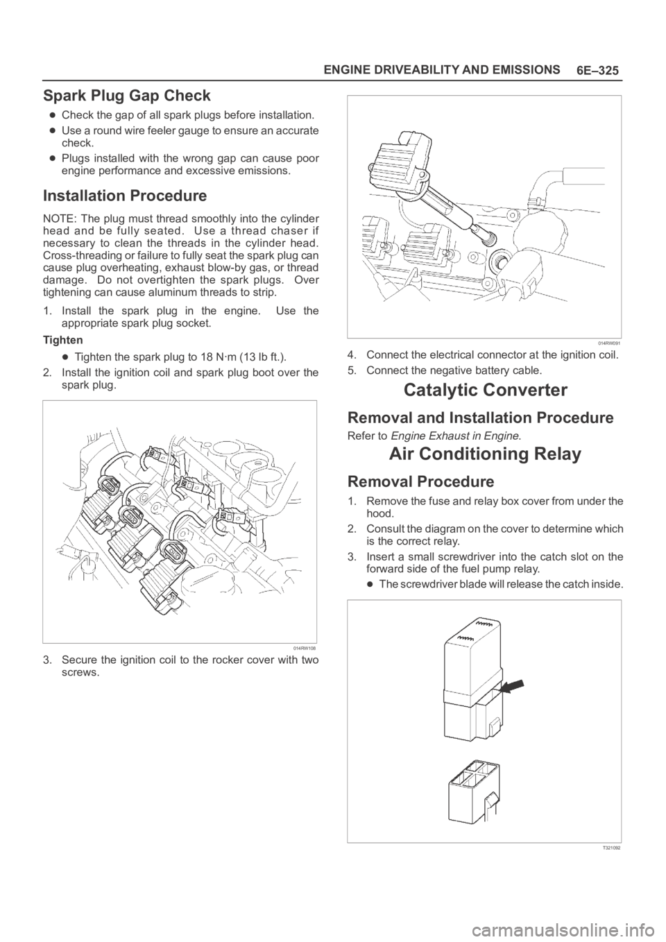
1. Install the spark plug in the engine. Use the
appropriate spark plug socket.
Tighten
Tighten the spark plug to 18 Nꞏm (13 lb ft.).
2. Install the ignition coil and spark plug boot over the
spark plug.
014RW108
3. Secure the ignition coil to the rocker cover with two
screws.
014RW091
4. Connect the electrical connector at the ignition coil.
5. Connect the negative battery cable.
Catalytic Converter
Removal and Installation Procedure
Refer to Engine Exhaust in Engine.
Air Conditioning Relay
Removal Procedure
1. Remove the fuse and relay box cover from under the
hood.
2. Consult the diagram on the cover to determine which
is the correct relay.
3. Insert a small screwdriver into the catch slot on the
forward side of the fuel pump relay.
The screwdriver blade will release the catch inside.
T321092
Page 1465 of 6000
6E–348
ENGINE DRIVEABILITY AND EMISSIONS
oil to enter the cylinder, particularly if the deposits are
heavier on the side of the spark plug facing the intake
valve.
TS23995
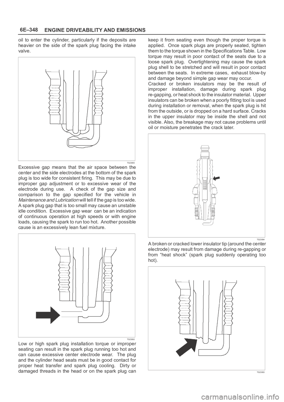
Excessive gap means that the air space between the
center and the side electrodes at the bottom of the spark
plug is too wide for consistent firing. This may be due to
improper gap adjustment or to excessive wear of the
electrode during use. A check of the gap size and
comparison to the gap specified for the vehicle in
Maintenance and Lubrication will tell if the gap is too wide.
A spark plug gap that is too small may cause an unstable
idle condition. Excessive gap wear can be an indication
of continuous operation at high speeds or with engine
loads, causing the spark to run too hot. Another possible
cause is an excessively lean fuel mixture.
TS23992
Low or high spark plug installation torque or improper
seating can result in the spark plug running too hot and
can cause excessive center electrode wear. The plug
and the cylinder head seats must be in good contact for
proper heat transfer and spark plug cooling. Dirty or
damaged threads in the head or on the spark plug cankeep it from seating even though the proper torque is
applied. Once spark plugs are properly seated, tighten
them to the torque shown in the Specifications Table. Low
torque may result in poor contact of the seats due to a
loose spark plug. Overtightening may cause the spark
plug shell to be stretched and will result in poor contact
between the seats. In extreme cases, exhaust blow-by
and damage beyond simple gap wear may occur.
Cracked or broken insulators may be the result of
improper installation, damage during spark plug
re-gapping, or heat shock to the insulator material. Upper
insulators can be broken when a poorly fitting tool is used
during installation or removal, when the spark plug is hit
from the outside, or is dropped on a hard surface. Cracks
in the upper insulator may be inside the shell and not
visible. Also, the breakage may not cause problems until
oil or moisture penetrates the crack later.
TS23994
A broken or cracked lower insulator tip (around the center
electrode) may result from damage during re-gapping or
from “heat shock” (spark plug suddenly operating too
hot).
TS23993
Page 1483 of 6000
6G–4
ENGINE LUBRICATION
11. Remove drive gear.
12. Remove oil seal.
13. Remove O-ring.
Inspection and Repair
CAUTION: Make necessary correction or parts
replacement if wear, damage or any other abnormal
conditions are found during inspection.
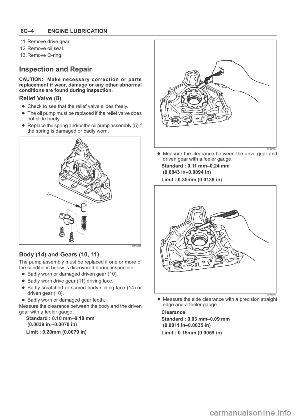
Relief Valve (8)
Check to see that the relief valve slides freely.
The oil pump must be replaced if the relief valve does
not slide freely.
Replace the spring and/or the oil pump assembly (5) if
the spring is damaged or badly worn.
051RS002
Body (14) and Gears (10, 11)
The pump assembly must be replaced if one or more of
the conditions below is discovered during inspection.
Badly worn or damaged driven gear (10).
Badly worn drive gear (11) driving face.
Badly scratched or scored body sliding face (14) or
driven gear (10).
Badly worn or damaged gear teeth.
Measure the clearance between the body and the driven
gear with a feeler gauge.
Standard : 0.10 mm–0.18 mm
(0.0039 in.–0.0070 in)
Limit : 0.20mm (0.0079 in)
051RS004
Measure the clearance between the drive gear and
driven gear with a feeler gauge.
Standard : 0.11 mm–0.24 mm
(0.0043 in–0.0094 in)
Limit : 0.35mm (0.0138 in)
051RS003
Measure the side clearance with a precision straight
edge and a feeler gauge.
Clearance
Standard : 0.03 mm–0.09 mm
(0.0011 in–0.0035 in)
Limit : 0.15mm (0.0059 in)