1998 OPEL FRONTERA sensor
[x] Cancel search: sensorPage 5676 of 6000

ENGINE SPEED CONTROL 6H – 3
REMOVAL
1. For vehicle with MT
1) Remove harness connector from accelerator
pedal sensor.
2) Remove accelerator pedal assembly from
chassis.
2. For vehicle with A/T
1) Remove A/T control cable from accelerator
pedal assembly.
2) Remove harness connector from accelerator
pedal sensor.
3) Remove accelerator pedal assembly from
chassis.
INSPECTION AND REPAIR
1. Check moving condition of accelerator pedal, if not
smooth working, apply oil to the pivot etc.
2. Check tightening condition of accelerator sensor, if
not completely tightened, it should be tightened
additionally.
INSTALLATION
The installation for both MT and A/T vehicles follows the
reverse manner of removal.
ENGINE SPEED CONTROL
Page 5686 of 6000

INDUCTION 6J – 9
REMOVAL
1. Remove intercooler assembly.
Refer to “Intercooler” in this manual.
2. Remove harness connector from motor and ITP
sensor.
3. Loosen the two fixing nuts and remove the throttle
valve assembly.
Legend
(1) Motor
(2) Intake Throttle Valve
(3) ITP sensor
INSPECTION AND REPAIR
1. Check for catching somwhere on the throttle valve.
2. If some problem is discovered during inspection on
the throttle valve, the throttle valve must replace.
INSTALLATION
1. Put gasket on the intake manifold and install throttle
valve.
2. Tighten nuts to the specified torque.
Torque: 20 Nꞏm (2.0 kgꞏm / 14.5 lb ft)
3. Reconnect harness connector to motor and
ITPsensor.
4. Install intercooler assembly.
1 2 3
025RW032
INTAKE THROTTLE VALVE
Page 5687 of 6000

6J – 10 INDUCTION
INTAKE MANIFOLD
REMOVAL
1. Drain engine coolant and remove water hose from
thermostat housing
2. Remove intercooler assembly.
3. Remove bracket fixing bolt of oil level gauge guide
tube.
4. Remove PCV hose.
5. Remove hoses from EGR valve, EGR vacuum
sensor and outlet of heater unit.
6. Disconnect harness connector from MAP sensor,
EGR vacuum sensor, ETC sensor, Water
temperature unit, IAT sensor and EVRV.
7. Remove high pressure oil pipe.
8. Remove two way check valve.
9. Remove fuel pipe.
10. Remove fixing bolts and nuts of intake manifold,
remove intake manifold assembly.
Legend
(1) Intake manifold
(2) Fixing portion of throttle valve
(3) EGR passage
(4) EGR valve
2
3
4
1
Legend
(1) Intake Manifold
(2) Throttle Valve Assembly
(3) EGR Valve
(4) Gasket
025RW022
3124
025RW031
Page 5688 of 6000

INDUCTION 6J – 11
INSPECTION AND RAPAIR
1. Visually check for cracks/clogs inside intake
manifold.
2. If foreign material is observed, it should be taken
out, and if there are some cracks on the intake
manifold, it must be replaced.
INSTALLATION
1. Install the intake manifold assembly, tighten bolts
and to the specified torque.
Torque: 20 Nꞏm (2.0 kgꞏm / 14.5 lb ft) for bolt
Torque: 20 Nꞏm (2.0 kgꞏm / 14.5 lb ft) for nut
2. Install fuel pipe.
Torque: 4 Nꞏm (0.4 kgꞏm / 2.9 lb ft) for M16 nut
(Apply engine oil)
Torque: 13 Nꞏm (1.3 kgꞏm / 9.4 lb ft) for M10 cap nut
Torque: 14 Nꞏm (1.4 kgꞏm / 10 lb ft) for M10
(Apply engine oil)
3. Install two way check valve.
Torque: 20 Nꞏm (2.0 kgꞏm / 14.5 lb ft)
4. Fill with about 300 cc of engine oil from the high
pressure oil pipe installation port of the oil rail using
an oil filler.
If assembled without filling the oil rail with oil, the
time for engine starting will be longer.
5. Install high pressure oil pipe, then tighten sleeve nut
to the specified torque.
Torque: 29 Nꞏm (3.0 kgꞏm / 21.7 lb ft)
6. Reconnect harness connector to MAP sensor, EGR
vacuum sensor, ETC sensor, Water thermo unit,
IAT sensor and EVRV sensor.
7. Install hoses to EGR valve, EGR vacuum sensor
and Water outlet of heater.
8. Connect PCV hose.
9. Install oil level gauge guide and fix it.
10. Install intercooler assembly.
Refer to “Intercooler” in this manual.
11. Install water hose to thermostat housing and fill with
engine coolant.
Model of Turbocharger IHI RHF5
Turbine Maximum Speed 180,000 rpm
Maximum Inlet Gas Temperature 800 °C (1472 °F)
Vibration Peak (G) criteria Maximum 4 (G) at Turbine Rotor Speed 140,000 rpm
Tolerance Limit of Compressor Blade Height Less then 0.5 mm (0.0197 in)
MAIN DATA AND SPECIFICATIONS
Page 5690 of 6000

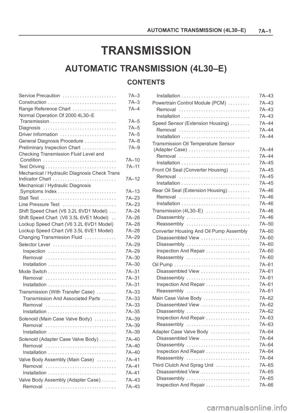
7A–1 AUTOMATIC TRANSMISSION (4L30–E)
TRANSMISSION
AUTOMATIC TRANSMISSION (4L30–E)
CONTENTS
Service Precaution 7A–3. . . . . . . . . . . . . . . . . . . . . .
Construction 7A–3. . . . . . . . . . . . . . . . . . . . . . . . . . . .
Range Reference Chart 7A–4. . . . . . . . . . . . . . . . . .
Normal Operation Of 2000 4L30–E
Transmission 7A–5. . . . . . . . . . . . . . . . . . . . . . . . . . .
Diagnosis 7A–5. . . . . . . . . . . . . . . . . . . . . . . . . . . . . .
Driver Information 7A–5. . . . . . . . . . . . . . . . . . . . . . .
General Diagnosis Procedure 7A–8. . . . . . . . . . . . .
Preliminary Inspection Chart 7A–9. . . . . . . . . . . . . .
Checking Transmission Fluid Level and
Condition 7A–10. . . . . . . . . . . . . . . . . . . . . . . . . . . . . .
Test Driving 7A–11. . . . . . . . . . . . . . . . . . . . . . . . . . . . .
Mechanical / Hydraulic Diagnosis Check Trans
Indicator Chart 7A–12. . . . . . . . . . . . . . . . . . . . . . . . . .
Mechanical / Hydraulic Diagnosis
Symptoms Index 7A–13. . . . . . . . . . . . . . . . . . . . . . . .
Stall Test 7A–23. . . . . . . . . . . . . . . . . . . . . . . . . . . . . . .
Line Pressure Test 7A–23. . . . . . . . . . . . . . . . . . . . . .
Shift Speed Chart (V6 3.2L 6VD1 Model) 7A–24. . .
Shift Speed Chart (V6 3.5L 6VE1 Model) 7A–26. .
Lockup Speed Chart (V6 3.2L 6VD1 Model) 7A–28
Lockup Speed Chart (V6 3.5L 6VE1 Model) 7A–28
Changing Transmission Fluid 7A–29. . . . . . . . . . . . .
Selector Lever 7A–29. . . . . . . . . . . . . . . . . . . . . . . . . .
Inspection 7A–29. . . . . . . . . . . . . . . . . . . . . . . . . . . .
Removal 7A–30. . . . . . . . . . . . . . . . . . . . . . . . . . . . .
Installation 7A–30. . . . . . . . . . . . . . . . . . . . . . . . . . . .
Mode Switch 7A–31. . . . . . . . . . . . . . . . . . . . . . . . . . . .
Removal 7A–31. . . . . . . . . . . . . . . . . . . . . . . . . . . . .
Installation 7A–31. . . . . . . . . . . . . . . . . . . . . . . . . . . .
Transmission (With Transfer Case) 7A–33. . . . . . . .
Transmission And Associated Parts 7A–33. . . . . .
Removal 7A–33. . . . . . . . . . . . . . . . . . . . . . . . . . . . .
Installation 7A–35. . . . . . . . . . . . . . . . . . . . . . . . . . . .
Solenoid (Main Case Valve Body) 7A–39. . . . . . . . .
Removal 7A–39. . . . . . . . . . . . . . . . . . . . . . . . . . . . .
Installation 7A–39. . . . . . . . . . . . . . . . . . . . . . . . . . . .
Solenoid (Adapter Case Valve Body) 7A–40. . . . . . .
Removal 7A–40. . . . . . . . . . . . . . . . . . . . . . . . . . . . .
Installation 7A–40. . . . . . . . . . . . . . . . . . . . . . . . . . . .
Valve Body Assembly (Main Case) 7A–41. . . . . . . .
Removal 7A–41. . . . . . . . . . . . . . . . . . . . . . . . . . . . .
Installation 7A–41. . . . . . . . . . . . . . . . . . . . . . . . . . . .
Valve Body Assembly (Adapter Case) 7A–43. . . . . .
Removal 7A–43. . . . . . . . . . . . . . . . . . . . . . . . . . . . . Installation 7A–43. . . . . . . . . . . . . . . . . . . . . . . . . . . .
Powertrain Control Module (PCM) 7A–43. . . . . . . . .
Removal 7A–43. . . . . . . . . . . . . . . . . . . . . . . . . . . . .
Installation 7A–43. . . . . . . . . . . . . . . . . . . . . . . . . . . .
Speed Sensor (Extension Housing) 7A–44. . . . . . . .
Removal 7A–44. . . . . . . . . . . . . . . . . . . . . . . . . . . . .
Installation 7A–44. . . . . . . . . . . . . . . . . . . . . . . . . . . .
Transmission Oil Temperature Sensor
(Adapter Case) 7A–44. . . . . . . . . . . . . . . . . . . . . . . . .
Removal 7A–44. . . . . . . . . . . . . . . . . . . . . . . . . . . . .
Installation 7A–45. . . . . . . . . . . . . . . . . . . . . . . . . . . .
Front Oil Seal (Converter Housing) 7A–45. . . . . . . .
Removal 7A–45. . . . . . . . . . . . . . . . . . . . . . . . . . . . .
Installation 7A–45. . . . . . . . . . . . . . . . . . . . . . . . . . . .
Rear Oil Seal (Extension Housing) 7A–46. . . . . . . . .
Removal 7A–46. . . . . . . . . . . . . . . . . . . . . . . . . . . . .
Installation 7A–46. . . . . . . . . . . . . . . . . . . . . . . . . . . .
Transmission (4L30–E) 7A–46. . . . . . . . . . . . . . . . . .
Disassembly 7A–46. . . . . . . . . . . . . . . . . . . . . . . . . .
Reassembly 7A–50. . . . . . . . . . . . . . . . . . . . . . . . . .
Converter Housing And Oil Pump Assembly 7A–60
Disassembled View 7A–60. . . . . . . . . . . . . . . . . . . .
Disassembly 7A–60. . . . . . . . . . . . . . . . . . . . . . . . . .
Inspection And Repair 7A–60. . . . . . . . . . . . . . . . . .
Reassembly 7A–60. . . . . . . . . . . . . . . . . . . . . . . . . .
Oil Pump 7A–61. . . . . . . . . . . . . . . . . . . . . . . . . . . . . . .
Disassembled View 7A–61. . . . . . . . . . . . . . . . . . . .
Disassembly 7A–61. . . . . . . . . . . . . . . . . . . . . . . . . .
Inspection And Repair 7A–61. . . . . . . . . . . . . . . . . .
Reassembly 7A–61. . . . . . . . . . . . . . . . . . . . . . . . . .
Main Case Valve Body 7A–62. . . . . . . . . . . . . . . . . . .
Disassembled View 7A–62. . . . . . . . . . . . . . . . . . . .
Disassembly 7A–62. . . . . . . . . . . . . . . . . . . . . . . . . .
Inspection And Repair 7A–63. . . . . . . . . . . . . . . . . .
Reassembly 7A–63. . . . . . . . . . . . . . . . . . . . . . . . . .
Adapter Case Valve Body 7A–64. . . . . . . . . . . . . . . .
Disassembled View 7A–64. . . . . . . . . . . . . . . . . . . .
Disassembly 7A–64. . . . . . . . . . . . . . . . . . . . . . . . . .
Inspection And Repair 7A–64. . . . . . . . . . . . . . . . . .
Reassembly 7A–64. . . . . . . . . . . . . . . . . . . . . . . . . .
Third Clutch And Sprag Unit 7A–65. . . . . . . . . . . . . .
Disassembled View 7A–65. . . . . . . . . . . . . . . . . . . .
Disassembly 7A–65. . . . . . . . . . . . . . . . . . . . . . . . . .
Inspection And Repair 7A–66. . . . . . . . . . . . . . . . . .
Page 5707 of 6000

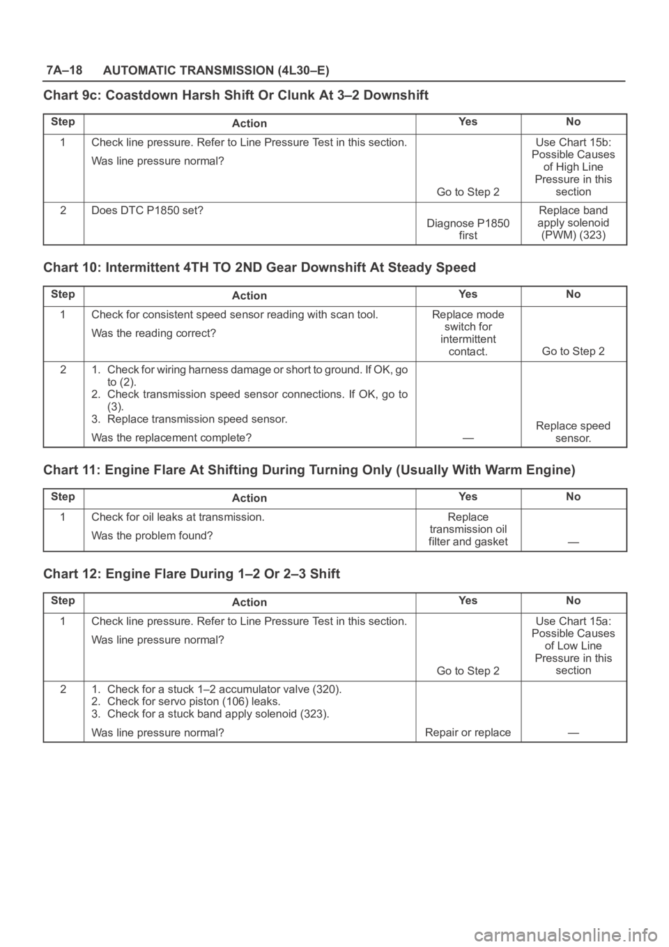
7A–18
AUTOMATIC TRANSMISSION (4L30–E)
Chart 9c: Coastdown Harsh Shift Or Clunk At 3–2 Downshift
StepActionYe sNo
1Check line pressure. Refer to Line Pressure Test in this section.
Was line pressure normal?
Go to Step 2
Use Chart 15b:
Possible Causes
of High Line
Pressure in this
section
2Does DTC P1850 set?
Diagnose P1850
first
Replace band
apply solenoid
(PWM) (323)
Chart 10: Intermittent 4TH TO 2ND Gear Downshift At Steady Speed
StepActionYe sNo
1Check for consistent speed sensor reading with scan tool.
Was the reading correct?Replace mode
switch for
intermittent
contact.
Go to Step 2
21. Check for wiring harness damage or short to ground. If OK, go
to (2).
2. Check transmission speed sensor connections. If OK, go to
(3).
3. Replace transmission speed sensor.
Was the replacement complete?
—
Replace speed
sensor.
Chart 11: Engine Flare At Shifting During Turning Only (Usually With Warm Engine)
StepActionYe sNo
1Check for oil leaks at transmission.
Was the problem found?Replace
transmission oil
filter and gasket
—
Chart 12: Engine Flare During 1–2 Or 2–3 Shift
StepActionYe sNo
1Check line pressure. Refer to Line Pressure Test in this section.
Was line pressure normal?
Go to Step 2
Use Chart 15a:
Possible Causes
of Low Line
Pressure in this
section
21. Check for a stuck 1–2 accumulator valve (320).
2. Check for servo piston (106) leaks.
3. Check for a stuck band apply solenoid (323).
Was line pressure normal?
Repair or replace—
Page 5709 of 6000

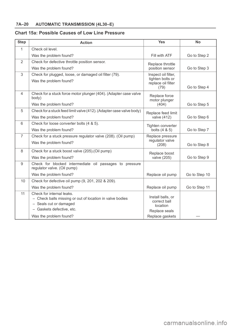
7A–20
AUTOMATIC TRANSMISSION (4L30–E)
Chart 15a: Possible Causes of Low Line Pressure
StepActionYe sNo
1Check oil level.
Was the problem found?
Fill with ATFGo to Step 2
2Check for defective throttle position sensor.
Was the problem found?Replace throttle
position sensor
Go to Step 3
3Check for plugged, loose, or damaged oil filter (79).
Was the problem found?Inspect oil filter,
tighten bolts or
replace oil filter
(79)
Go to Step 4
4Check for a stuck force motor plunger (404). (Adapter case valve
body)
Was the problem found?Replace force
motor plunger
(404)
Go to Step 5
5Check for a stuck feed limit valve (412). (Adapter case valve body)
Was the problem found?Replace feed limit
valve (412)
Go to Step 6
6Check for loose converter bolts (4 & 5).
Was the problem found?Tighten converter
bolts (4 & 5)
Go to Step 7
7Check for a stuck pressure regulator valve (208). (Oil pump)
Was the problem found?Replace pressure
regulator valve
(208)
Go to Step 8
8Check for a stuck boost valve (205).(Oil pump)
Was the problem found?Replace boost
valve (205)
Go to Step 9
9Check for blocked intermediate oil passages to pressure
regulator valve. (Oil pump)
Was the problem found?
Replace oil pumpGo to Step 10
10Check for defective oil pump (9, 201, 202 & 209).
Was the problem found?
Replace oil pumpGo to Step 11
11Check for internal leaks.
– Check balls missing or out of location in valve bodies
– Seals cut or damaged
– Gaskets defective, etc.
Was the problem found?Install balls, or
correct ball
location
Replace seals
Replace gaskets
—
Page 5710 of 6000

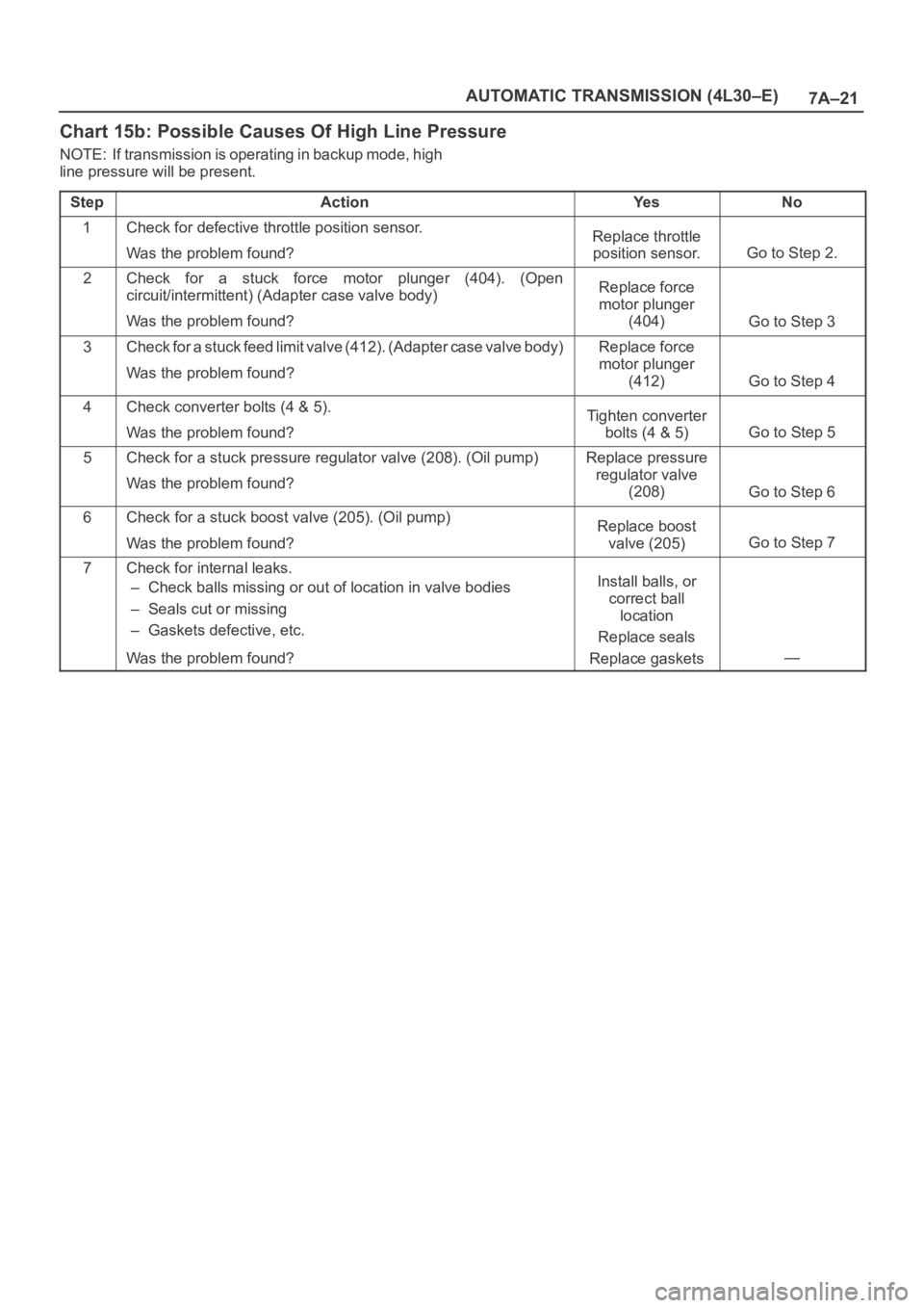
7A–21 AUTOMATIC TRANSMISSION (4L30–E)
Chart 15b: Possible Causes Of High Line Pressure
NOTE: If transmission is operating in backup mode, high
line pressure will be present.
Step
ActionYe sNo
1Check for defective throttle position sensor.
Was the problem found?Replace throttle
position sensor.
Go to Step 2.
2Check for a stuck force motor plunger (404). (Open
circuit/intermittent) (Adapter case valve body)
Was the problem found?Replace force
motor plunger
(404)
Go to Step 3
3Check for a stuck feed limit valve (412). (Adapter case valve body)
Was the problem found?Replace force
motor plunger
(412)
Go to Step 4
4Check converter bolts (4 & 5).
Was the problem found?Tighten converter
bolts (4 & 5)
Go to Step 5
5Check for a stuck pressure regulator valve (208). (Oil pump)
Was the problem found?Replace pressure
regulator valve
(208)
Go to Step 6
6Check for a stuck boost valve (205). (Oil pump)
Was the problem found?Replace boost
valve (205)
Go to Step 7
7Check for internal leaks.
– Check balls missing or out of location in valve bodies
– Seals cut or missing
– Gaskets defective, etc.
Was the problem found?Install balls, or
correct ball
location
Replace seals
Replace gaskets
—