1998 OPEL FRONTERA check engine
[x] Cancel search: check enginePage 5419 of 6000
6D – 16 ENGINE ELECTRICAL
DIAGNOSIS
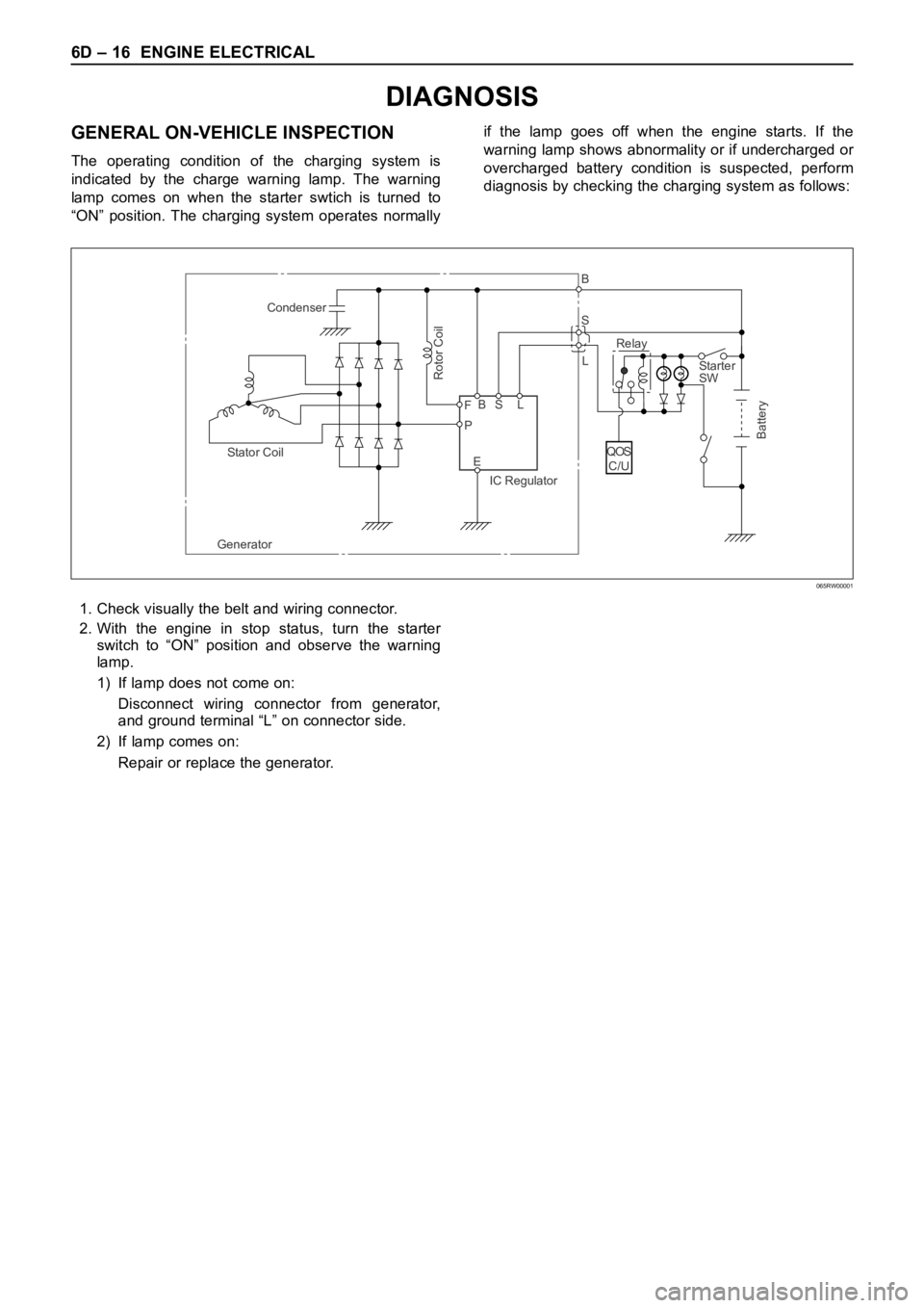
GENERAL ON-VEHICLE INSPECTION
The operating condition of the charging system is
indicated by the charge warning lamp. The warning
lamp comes on when the starter swtich is turned to
“ON” position. The charging system operates normallyif the lamp goes off when the engine starts. If the
warning lamp shows abnormality or if undercharged or
overcharged battery condition is suspected, perform
diagnosis by checking the charging system as follows:
Condenser
GeneratorStator Coil
IC RegulatorStarter
SW
Rotor Coil
Battery
P F
EBS LRelay B
S
L
QOS
C/U
065RW00001
1. Check visually the belt and wiring connector.
2. With the engine in stop status, turn the starter
switch to “ON” position and observe the warning
lamp.
1) If lamp does not come on:
Disconnect wiring connector from generator,
and ground terminal “L” on connector side.
2) If lamp comes on:
Repair or replace the generator.
Page 5422 of 6000
ENGINE ELECTRICAL 6D – 19
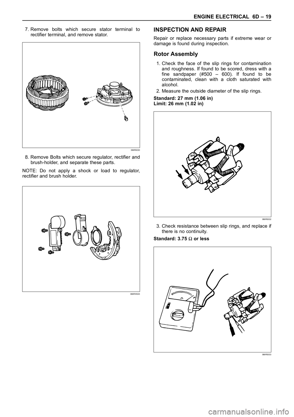
7. Remove bolts which secure stator terminal to
rectifier terminal, and remove stator.
8. Remove Bolts which secure regulator, rectifier and
brush-holder, and separate these parts.
NOTE: Do not apply a shock or load to regulator,
rectifier and brush holder.INSPECTION AND REPAIR
Repair or replace necessary parts if extreme wear or
damage is found during inspection.
Rotor Assembly
1. Check the face of the slip rings for contamination
and roughness. If found to be scored, dress with a
fine sandpaper (#500 – 600). If found to be
contaminated, clean with a cloth saturated with
alcohol.
2. Measure the outside diameter of the slip rings.
Standard: 27 mm (1.06 in)
Limit: 26 mm (1.02 in)
3. Check resistance between slip rings, and replace if
there is no continuity.
Standard: 3.75
or less
066RS030
066RW025
066RS032
066RS033
Page 5423 of 6000
6D – 20 ENGINE ELECTRICAL
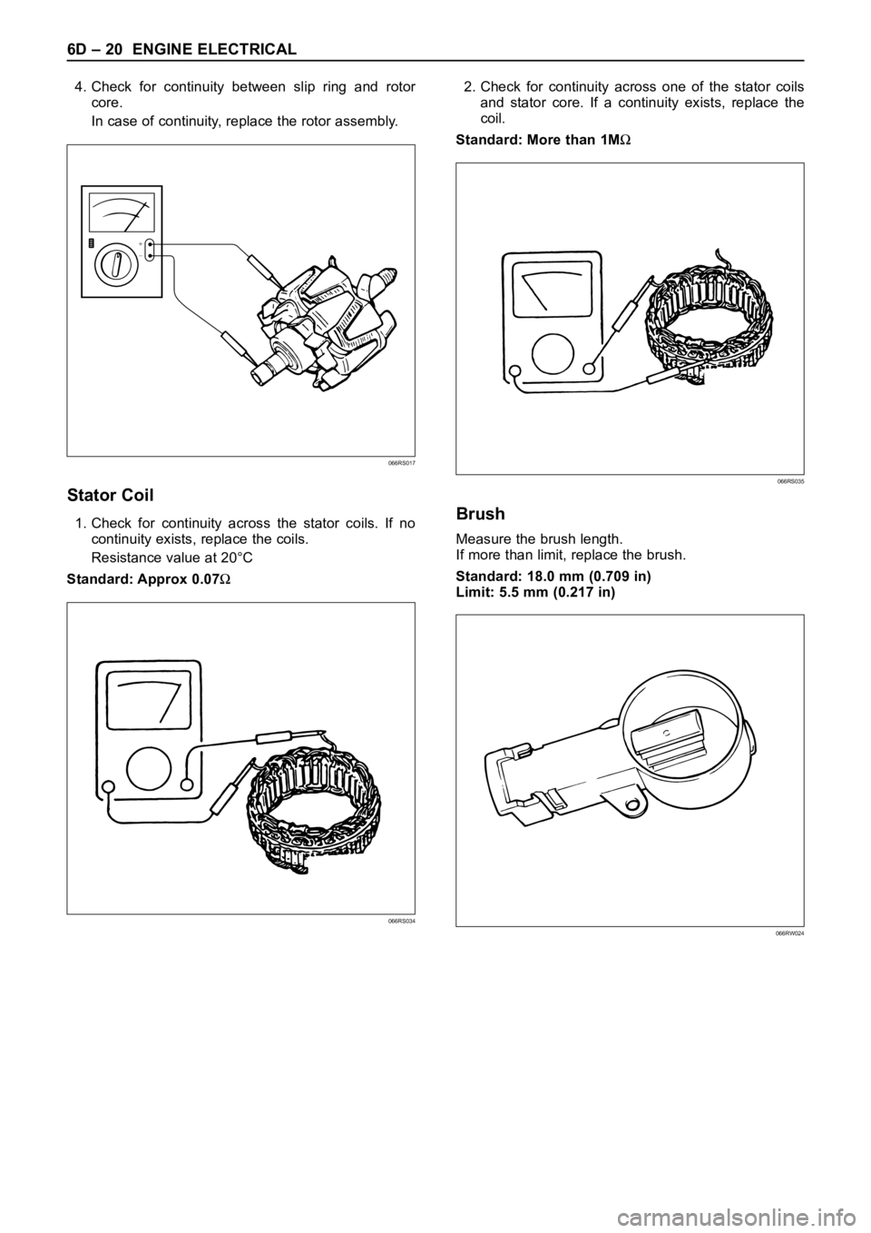
4. Check for continuity between slip ring and rotor
core.
In case of continuity, replace the rotor assembly.
Stator Coil
1. Check for continuity across the stator coils. If no
continuity exists, replace the coils.
Resistance value at 20°C
Standard: Approx 0.07
2. Check for continuity across one of the stator coils
and stator core. If a continuity exists, replace the
coil.
Standard: More than 1M
Brush
Measure the brush length.
If more than limit, replace the brush.
Standard: 18.0 mm (0.709 in)
Limit: 5.5 mm (0.217 in)
+
−
066RS017
066RS035
066RW024066RS034
Page 5424 of 6000
ENGINE ELECTRICAL 6D – 21
Rectifier Assembly
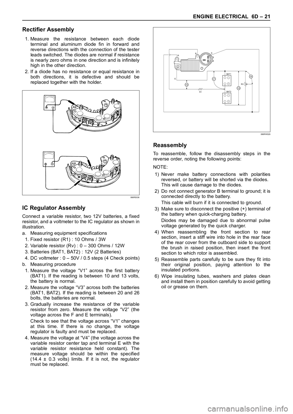
1. Measure the resistance between each diode
terminal and aluminum diode fin in forward and
reverse directions with the connection of the tester
leads switched. The diodes are normal if resistance
is nearly zero ohms in one direction and is infinitely
high in the other direction.
2. If a diode has no resistance or equal resistance in
both directions, it is defective and should be
replaced together with the holder.
IC Regulator Assembly
Connect a variable resistor, two 12V batteries, a fixed
resistor, and a voltmeter to the IC regulator as shown in
illustration.
a. Measuring equipment specifications
1. Fixed resistor (R1) : 10 Ohms / 3W
2. Variable resistor (Rv) : 0 – 300 Ohms / 12W
3. Batteries (BAT1, BAT2) : 12V (2 Batteries)
4. DC voltmeter : 0 – 50V / 0.5 steps (4 Check points)
b. Measuring procedure
1. Measure the voltage “V1” across the first battery
(BAT1). If the reading is between 10 and 13 volts,
the battery is normal.
2. Measure the voltage “V3” across both the batteries
(BAT1, BAT2). If the reading is between 20 and 26
bolts, the batteries are normal.
3. Gradually increase the resistance of the variable
resistor from zero. Measure the voltage “V2” (the
voltage across the F and E terminals).
Check to see that the voltage across “V1” changes
at this time. If there is no change, the voltage
regulator is faulty and must be replaced.
4. Measure the voltage at “V4” (the voltage across the
variable resistor center tap and terminal E with the
variable resistor resistance held constant). The
measure voltage should be within the specified
(14.4 ± 0.3 volts) limits. If it is not, the regulator
must be replaced.
Reassembly
To reassemble, follow the disassembly steps in the
reverse order, noting the following points:
NOTE:
1) Never make battery connections with polarities
reversed, or battery will be shorted via the diodes.
This will cause damage to the diodes.
2) Do not connect generator B terminal to ground; it is
connected directly to the battery.
This cable will burn if it is connected to ground.
3) Make sure to disconnect the positive (+) terminal of
the battery when quick-charging battery.
Diodes may be damaged due to abnormal pulse
voltage generated by the quick charger.
4) When reassembling the front section to rear
section, insert a stiff wire into hole in the rear face
of the rear cover from the outboard side to support
the brush in raised position, then insert the front
section to which rotor is assembled.
5) Reassemble parts carefully to be sure they fit into
their original position, paying attention to the
insulated portions.
6) Wipe insulating tubes, washers and plates clean
and install them in position carefully to avoid getting
oil or grease on them.
066RS036
R
EBS
R1RV
BAT2 BAT1
V2V3
V4V1+
−
+
−
066RW029
Page 5430 of 6000
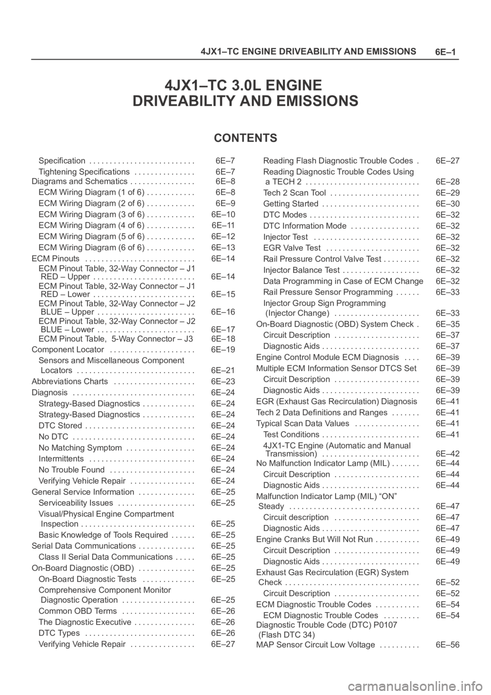
6E–1 4JX1–TC ENGINE DRIVEABILITY AND EMISSIONS
4JX1–TC 3.0L ENGINE
DRIVEABILITY AND EMISSIONS
CONTENTS
Specification 6E–7. . . . . . . . . . . . . . . . . . . . . . . . . .
Tightening Specifications 6E–7. . . . . . . . . . . . . . .
Diagrams and Schematics 6E–8. . . . . . . . . . . . . . . .
ECM Wiring Diagram (1 of 6) 6E–8. . . . . . . . . . . .
ECM Wiring Diagram (2 of 6) 6E–9. . . . . . . . . . . .
ECM Wiring Diagram (3 of 6) 6E–10. . . . . . . . . . . .
ECM Wiring Diagram (4 of 6) 6E–11. . . . . . . . . . . .
ECM Wiring Diagram (5 of 6) 6E–12. . . . . . . . . . . .
ECM Wiring Diagram (6 of 6) 6E–13. . . . . . . . . . . .
ECM Pinouts 6E–14. . . . . . . . . . . . . . . . . . . . . . . . . . .
ECM Pinout Table, 32-Way Connector – J1
RED – Upper 6E–14. . . . . . . . . . . . . . . . . . . . . . . . .
ECM Pinout Table, 32-Way Connector – J1
RED – Lower 6E–15. . . . . . . . . . . . . . . . . . . . . . . . .
ECM Pinout Table, 32-Way Connector – J2
BLUE – Upper 6E–16. . . . . . . . . . . . . . . . . . . . . . . .
ECM Pinout Table, 32-Way Connector – J2
BLUE – Lower 6E–17. . . . . . . . . . . . . . . . . . . . . . . .
ECM Pinout Table, 5-Way Connector – J3 6E–18
Component Locator 6E–19. . . . . . . . . . . . . . . . . . . . .
Sensors and Miscellaneous Component
Locators 6E–21. . . . . . . . . . . . . . . . . . . . . . . . . . . . .
Abbreviations Charts 6E–23. . . . . . . . . . . . . . . . . . . .
Diagnosis 6E–24. . . . . . . . . . . . . . . . . . . . . . . . . . . . . .
Strategy-Based Diagnostics 6E–24. . . . . . . . . . . . .
Strategy-Based Diagnostics 6E–24. . . . . . . . . . . . .
DTC Stored 6E–24. . . . . . . . . . . . . . . . . . . . . . . . . . .
No DTC 6E–24. . . . . . . . . . . . . . . . . . . . . . . . . . . . . .
No Matching Symptom 6E–24. . . . . . . . . . . . . . . . .
Intermittents 6E–24. . . . . . . . . . . . . . . . . . . . . . . . . .
No Trouble Found 6E–24. . . . . . . . . . . . . . . . . . . . .
Verifying Vehicle Repair 6E–24. . . . . . . . . . . . . . . .
General Service Information 6E–25. . . . . . . . . . . . . .
Serviceability Issues 6E–25. . . . . . . . . . . . . . . . . . .
Visual/Physical Engine Compartment
Inspection 6E–25. . . . . . . . . . . . . . . . . . . . . . . . . . . .
Basic Knowledge of Tools Required 6E–25. . . . . .
Serial Data Communications 6E–25. . . . . . . . . . . . . .
Class II Serial Data Communications 6E–25. . . . .
On-Board Diagnostic (OBD) 6E–25. . . . . . . . . . . . . .
On-Board Diagnostic Tests 6E–25. . . . . . . . . . . . .
Comprehensive Component Monitor
Diagnostic Operation 6E–25. . . . . . . . . . . . . . . . . .
Common OBD Terms 6E–26. . . . . . . . . . . . . . . . . .
The Diagnostic Executive 6E–26. . . . . . . . . . . . . . .
DTC Types 6E–26. . . . . . . . . . . . . . . . . . . . . . . . . . .
Verifying Vehicle Repair 6E–27. . . . . . . . . . . . . . . . Reading Flash Diagnostic Trouble Codes 6E–27.
Reading Diagnostic Trouble Codes Using
a TECH 2 6E–28. . . . . . . . . . . . . . . . . . . . . . . . . . . .
Tech 2 Scan Tool 6E–29. . . . . . . . . . . . . . . . . . . . . .
Getting Started 6E–30. . . . . . . . . . . . . . . . . . . . . . . .
DTC Modes 6E–32. . . . . . . . . . . . . . . . . . . . . . . . . . .
DTC Information Mode 6E–32. . . . . . . . . . . . . . . . .
Injector Test 6E–32. . . . . . . . . . . . . . . . . . . . . . . . . .
EGR Valve Test 6E–32. . . . . . . . . . . . . . . . . . . . . . .
Rail Pressure Control Valve Test 6E–32. . . . . . . . .
Injector Balance Test 6E–32. . . . . . . . . . . . . . . . . . .
Data Programming in Case of ECM Change 6E–32
Rail Pressure Sensor Programming 6E–33. . . . . .
Injector Group Sign Programming
(Injector Change) 6E–33. . . . . . . . . . . . . . . . . . . . .
On-Board Diagnostic (OBD) System Check 6E–35.
Circuit Description 6E–37. . . . . . . . . . . . . . . . . . . . .
Diagnostic Aids 6E–37. . . . . . . . . . . . . . . . . . . . . . . .
Engine Control Module ECM Diagnosis 6E–39. . . .
Multiple ECM Information Sensor DTCS Set 6E–39
Circuit Description 6E–39. . . . . . . . . . . . . . . . . . . . .
Diagnostic Aids 6E–39. . . . . . . . . . . . . . . . . . . . . . . .
EGR (Exhaust Gas Recirculation) Diagnosis 6E–41
Tech 2 Data Definitions and Ranges 6E–41. . . . . . .
Typical Scan Data Values 6E–41. . . . . . . . . . . . . . . .
Test Conditions 6E–41. . . . . . . . . . . . . . . . . . . . . . . .
4JX1-TC Engine (Automatic and Manual
Transmission) 6E–42. . . . . . . . . . . . . . . . . . . . . . . .
No Malfunction Indicator Lamp (MIL) 6E–44. . . . . . .
Circuit Description 6E–44. . . . . . . . . . . . . . . . . . . . .
Diagnostic Aids 6E–44. . . . . . . . . . . . . . . . . . . . . . . .
Malfunction Indicator Lamp (MIL) “ON”
Steady 6E–47. . . . . . . . . . . . . . . . . . . . . . . . . . . . . . . .
Circuit description 6E–47. . . . . . . . . . . . . . . . . . . . .
Diagnostic Aids 6E–47. . . . . . . . . . . . . . . . . . . . . . . .
Engine Cranks But Will Not Run 6E–49. . . . . . . . . . .
Circuit Description 6E–49. . . . . . . . . . . . . . . . . . . . .
Diagnostic Aids 6E–49. . . . . . . . . . . . . . . . . . . . . . . .
Exhaust Gas Recirculation (EGR) System
Check 6E–52. . . . . . . . . . . . . . . . . . . . . . . . . . . . . . . . .
Circuit Description 6E–52. . . . . . . . . . . . . . . . . . . . .
ECM Diagnostic Trouble Codes 6E–54. . . . . . . . . . .
ECM Diagnostic Trouble Codes 6E–54. . . . . . . . .
Diagnostic Trouble Code (DTC) P0107
(Flash DTC 34)
MAP Sensor Circuit Low Voltage 6E–56. . . . . . . . . .
Page 5434 of 6000
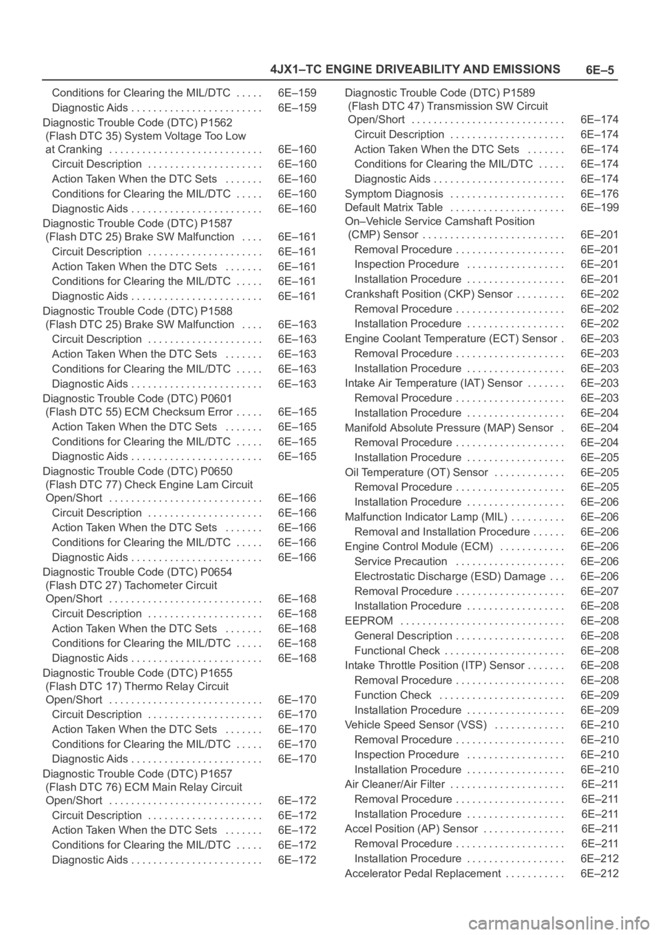
6E–5 4JX1–TC ENGINE DRIVEABILITY AND EMISSIONS
Conditions for Clearing the MIL/DTC 6E–159. . . . .
Diagnostic Aids 6E–159. . . . . . . . . . . . . . . . . . . . . . . .
Diagnostic Trouble Code (DTC) P1562
(Flash DTC 35) System Voltage Too Low
at Cranking 6E–160. . . . . . . . . . . . . . . . . . . . . . . . . . . .
Circuit Description 6E–160. . . . . . . . . . . . . . . . . . . . .
Action Taken When the DTC Sets 6E–160. . . . . . .
Conditions for Clearing the MIL/DTC 6E–160. . . . .
Diagnostic Aids 6E–160. . . . . . . . . . . . . . . . . . . . . . . .
Diagnostic Trouble Code (DTC) P1587
(Flash DTC 25) Brake SW Malfunction 6E–161. . . .
Circuit Description 6E–161. . . . . . . . . . . . . . . . . . . . .
Action Taken When the DTC Sets 6E–161. . . . . . .
Conditions for Clearing the MIL/DTC 6E–161. . . . .
Diagnostic Aids 6E–161. . . . . . . . . . . . . . . . . . . . . . . .
Diagnostic Trouble Code (DTC) P1588
(Flash DTC 25) Brake SW Malfunction 6E–163. . . .
Circuit Description 6E–163. . . . . . . . . . . . . . . . . . . . .
Action Taken When the DTC Sets 6E–163. . . . . . .
Conditions for Clearing the MIL/DTC 6E–163. . . . .
Diagnostic Aids 6E–163. . . . . . . . . . . . . . . . . . . . . . . .
Diagnostic Trouble Code (DTC) P0601
(Flash DTC 55) ECM Checksum Error 6E–165. . . . .
Action Taken When the DTC Sets 6E–165. . . . . . .
Conditions for Clearing the MIL/DTC 6E–165. . . . .
Diagnostic Aids 6E–165. . . . . . . . . . . . . . . . . . . . . . . .
Diagnostic Trouble Code (DTC) P0650
(Flash DTC 77) Check Engine Lam Circuit
Open/Short 6E–166. . . . . . . . . . . . . . . . . . . . . . . . . . . .
Circuit Description 6E–166. . . . . . . . . . . . . . . . . . . . .
Action Taken When the DTC Sets 6E–166. . . . . . .
Conditions for Clearing the MIL/DTC 6E–166. . . . .
Diagnostic Aids 6E–166. . . . . . . . . . . . . . . . . . . . . . . .
Diagnostic Trouble Code (DTC) P0654
(Flash DTC 27) Tachometer Circuit
Open/Short 6E–168. . . . . . . . . . . . . . . . . . . . . . . . . . . .
Circuit Description 6E–168. . . . . . . . . . . . . . . . . . . . .
Action Taken When the DTC Sets 6E–168. . . . . . .
Conditions for Clearing the MIL/DTC 6E–168. . . . .
Diagnostic Aids 6E–168. . . . . . . . . . . . . . . . . . . . . . . .
Diagnostic Trouble Code (DTC) P1655
(Flash DTC 17) Thermo Relay Circuit
Open/Short 6E–170. . . . . . . . . . . . . . . . . . . . . . . . . . . .
Circuit Description 6E–170. . . . . . . . . . . . . . . . . . . . .
Action Taken When the DTC Sets 6E–170. . . . . . .
Conditions for Clearing the MIL/DTC 6E–170. . . . .
Diagnostic Aids 6E–170. . . . . . . . . . . . . . . . . . . . . . . .
Diagnostic Trouble Code (DTC) P1657
(Flash DTC 76) ECM Main Relay Circuit
Open/Short 6E–172. . . . . . . . . . . . . . . . . . . . . . . . . . . .
Circuit Description 6E–172. . . . . . . . . . . . . . . . . . . . .
Action Taken When the DTC Sets 6E–172. . . . . . .
Conditions for Clearing the MIL/DTC 6E–172. . . . .
Diagnostic Aids 6E–172. . . . . . . . . . . . . . . . . . . . . . . . Diagnostic Trouble Code (DTC) P1589
(Flash DTC 47) Transmission SW Circuit
Open/Short 6E–174. . . . . . . . . . . . . . . . . . . . . . . . . . . .
Circuit Description 6E–174. . . . . . . . . . . . . . . . . . . . .
Action Taken When the DTC Sets 6E–174. . . . . . .
Conditions for Clearing the MIL/DTC 6E–174. . . . .
Diagnostic Aids 6E–174. . . . . . . . . . . . . . . . . . . . . . . .
Symptom Diagnosis 6E–176. . . . . . . . . . . . . . . . . . . . .
Default Matrix Table 6E–199. . . . . . . . . . . . . . . . . . . . .
On–Vehicle Service Camshaft Position
(CMP) Sensor 6E–201. . . . . . . . . . . . . . . . . . . . . . . . . .
Removal Procedure 6E–201. . . . . . . . . . . . . . . . . . . .
Inspection Procedure 6E–201. . . . . . . . . . . . . . . . . .
Installation Procedure 6E–201. . . . . . . . . . . . . . . . . .
Crankshaft Position (CKP) Sensor 6E–202. . . . . . . . .
Removal Procedure 6E–202. . . . . . . . . . . . . . . . . . . .
Installation Procedure 6E–202. . . . . . . . . . . . . . . . . .
Engine Coolant Temperature (ECT) Sensor 6E–203.
Removal Procedure 6E–203. . . . . . . . . . . . . . . . . . . .
Installation Procedure 6E–203. . . . . . . . . . . . . . . . . .
Intake Air Temperature (IAT) Sensor 6E–203. . . . . . .
Removal Procedure 6E–203. . . . . . . . . . . . . . . . . . . .
Installation Procedure 6E–204. . . . . . . . . . . . . . . . . .
Manifold Absolute Pressure (MAP) Sensor 6E–204.
Removal Procedure 6E–204. . . . . . . . . . . . . . . . . . . .
Installation Procedure 6E–205. . . . . . . . . . . . . . . . . .
Oil Temperature (OT) Sensor 6E–205. . . . . . . . . . . . .
Removal Procedure 6E–205. . . . . . . . . . . . . . . . . . . .
Installation Procedure 6E–206. . . . . . . . . . . . . . . . . .
Malfunction Indicator Lamp (MIL) 6E–206. . . . . . . . . .
Removal and Installation Procedure 6E–206. . . . . .
Engine Control Module (ECM) 6E–206. . . . . . . . . . . .
Service Precaution 6E–206. . . . . . . . . . . . . . . . . . . .
Electrostatic Discharge (ESD) Damage 6E–206. . .
Removal Procedure 6E–207. . . . . . . . . . . . . . . . . . . .
Installation Procedure 6E–208. . . . . . . . . . . . . . . . . .
EEPROM 6E–208. . . . . . . . . . . . . . . . . . . . . . . . . . . . . .
General Description 6E–208. . . . . . . . . . . . . . . . . . . .
Functional Check 6E–208. . . . . . . . . . . . . . . . . . . . . .
Intake Throttle Position (ITP) Sensor 6E–208. . . . . . .
Removal Procedure 6E–208. . . . . . . . . . . . . . . . . . . .
Function Check 6E–209. . . . . . . . . . . . . . . . . . . . . . .
Installation Procedure 6E–209. . . . . . . . . . . . . . . . . .
Vehicle Speed Sensor (VSS) 6E–210. . . . . . . . . . . . .
Removal Procedure 6E–210. . . . . . . . . . . . . . . . . . . .
Inspection Procedure 6E–210. . . . . . . . . . . . . . . . . .
Installation Procedure 6E–210. . . . . . . . . . . . . . . . . .
Air Cleaner/Air Filter 6E–211. . . . . . . . . . . . . . . . . . . . .
Removal Procedure 6E–211. . . . . . . . . . . . . . . . . . . .
Installation Procedure 6E–211. . . . . . . . . . . . . . . . . .
Accel Position (AP) Sensor 6E–211. . . . . . . . . . . . . . .
Removal Procedure 6E–211. . . . . . . . . . . . . . . . . . . .
Installation Procedure 6E–212. . . . . . . . . . . . . . . . . .
Accelerator Pedal Replacement 6E–212. . . . . . . . . . .
Page 5448 of 6000
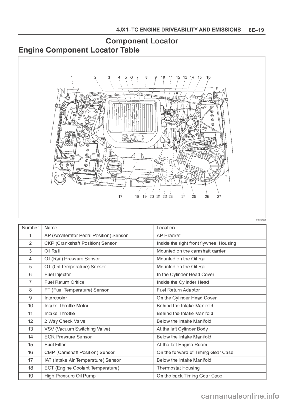
6E–19 4JX1–TC ENGINE DRIVEABILITY AND EMISSIONS
Component Locator
Engine Component Locator Table
F06RW051
NumberNameLocation
1AP (Accelerator Pedal Position) SensorAP Bracket
2CKP (Crankshaft Position) SensorInside the right front flywheel Housing
3Oil RailMounted on the camshaft carrier
4Oil (Rail) Pressure SensorMounted on the Oil Rail
5OT (Oil Temperature) SensorMounted on the Oil Rail
6Fuel InjectorIn the Cylinder Head Cover
7Fuel Return OrificeInside the Cylinder Head
8FT (Fuel Temperature) SensorFuel Return Adaptor
9IntercoolerOn the Cylinder Head Cover
10Intake Throttle MotorBehind the Intake Manifold
11Intake ThrottleBehind the Intake Manifold
122 Way Check ValveBelow the Intake Manifold
13VSV (Vacuum Switching Valve)At the left Cylinder Body
14EGR Pressure SensorBelow the Intake Manifold
15Fuel FilterAt the left Engine Room
16CMP (Camshaft Position) SensorOn the forward of Timing Gear Case
17IAT (Intake Air Temperature) SensorBelow the Intake Manifold
18ECT (Engine Coolant Temperature)Thermostat Housing
19High Pressure Oil PumpOn the back Timing Gear Case
Page 5453 of 6000
6E–24
4JX1–TC ENGINE DRIVEABILITY AND EMISSIONS
Diagnosis
Strategy-Based Diagnostics
Strategy-Based Diagnostics
The strategy-based diagnostic is a uniform approach to
repair all Electrical/Electronic (E/E) systems. The
diagnostic flow can always be used to resolve an E/E
system problem and is a starting point when repairs are
necessary. The following steps will instruct the technician
how to proceed with a diagnosis:
1. Verify the customer complaint.
To verify the customer complaint, the technician
should know the normal operation of the system.
2. Perform preliminary checks.
Conduct a thorough visual inspection.
Review the service history.
Detect unusual sounds or odors.
Gather diagnostic trouble code information to
achieve an effective repair.
3. Check bulletins and other service information.
This includes videos, newsletters, etc.
4. Refer to service information (manual) system
check(s).
“System checks” contain information on a system
that may not be supported by one or more DTCs.
System checks verify proper operation of the
system. This will lead the technician in an
organized approach to diagnostics.
5. Refer to service diagnostics.
DTC Stored
Follow the designated DTC chart exactly to make an
effective repair.
No DTC
Select the symptom from the symptom tables. Follow the
diagnostic paths or suggestions to complete the repair.
You may refer to the applicable component/system check
in the system checks.
No Matching Symptom
1. Analyze the complaint.
2. Develop a plan for diagnostics.
3. Utilize the wiring diagrams and the theory of
operation.
Call technical assistance for similar cases where repair
history may be available. Combine technician knowledge
with efficient use of the available service information.
Intermittents
Conditions that are not always present are called
intermittents. To resolve intermittents, perform the
following steps:
1. Observe history DTCs, DTC modes, and freezeframe
data.2. Evaluate the symptoms and the conditions described
by the customer.
3. Use a check sheet or other method to identify the
circuit or electrical system component.
4. Follow the suggestions for intermittent diagnosis
found in the service documentation.
Most scan tools, such as the Tech 2 and the DVM, have
data-capturing capabilities that can assist in detecting
intermittents.
No Trouble Found
This condition exists when the vehicle is found to operate
normally. The condition described by the customer may
be normal. Verify the customer complaint against another
vehicle that is operating normally. The condition may be
intermittent. Verify the complaint under the conditions
described by the customer before releasing the vehicle.
1. Re-examine the complaint.
When the complaint cannot be successfully found or
isolated, a re-evaluation is necessary. The complaint
should be re-verified and could be intermittent as
defined in
Intermittents, or could be normal.
2. Repair and verify.
After isolating the cause, the repairs should be made.
Validate for proper operation and verify that the
symptom has been corrected. This may involve road
testing or other methods to verify that the complaint
has been resolved under the following conditions:
Conditions noted by the customer.
If a DTC was diagnosed, verify a repair by
duplicating conditions present when the DTC was
set as noted in the Failure Records or Freeze
Frame data.
Verifying Vehicle Repair
Verification of the vehicle repair will be more
comprehensive for vehicles with OBD system
diagnostics. Following a repair, the technician should
perform the following steps:
IMPORTANT:Follow the steps below when you verify
repairs on OBD systems. Failure to follow these steps
could result in unnecessary repairs.
1. Review and record the Failure Records and the
Freeze Frame data for the DTC which has been
diagnosed (Freeze Frame data will only be stored for
the MIL (“Check Engine” lamp) has been requested).
2. Clear the DTC(s).
3. Operate the vehicle within conditions noted in the
Failure Records and Freeze Frame data.
4. Monitor the DTC status information for the specific
DTC which has been diagnosed until the diagnostic
test associated with that DTC runs.