Page 5359 of 6000
6A – 86 ENGINE MECHANICAL
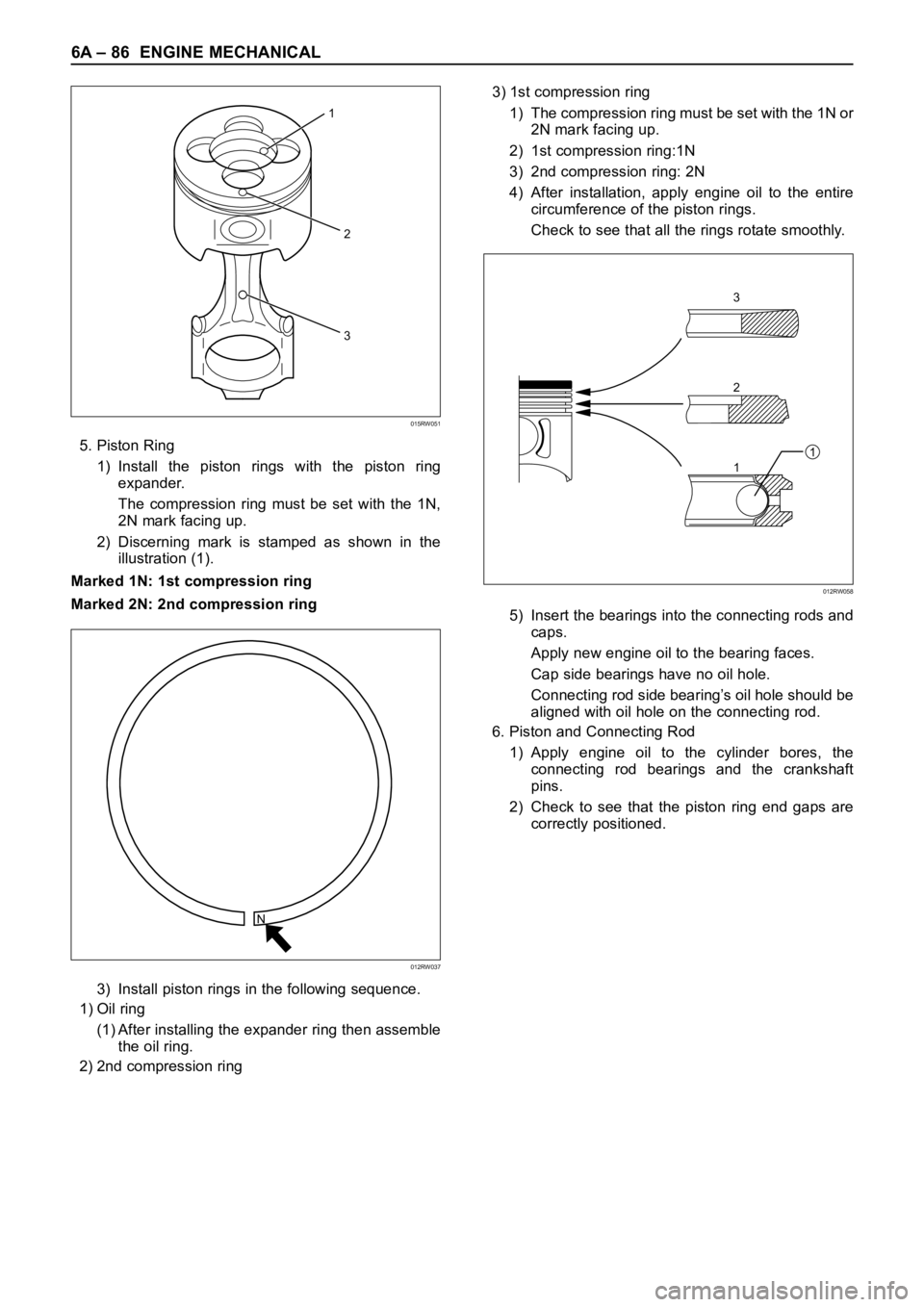
5. Piston Ring
1) Install the piston rings with the piston ring
expander.
The compression ring must be set with the 1N,
2N mark facing up.
2) Discerning mark is stamped as shown in the
illustration (1).
Marked 1N: 1st compression ring
Marked 2N: 2nd compression ring
3) Install piston rings in the following sequence.
1) Oil ring
(1) After installing the expander ring then assemble
the oil ring.
2) 2nd compression ring3) 1st compression ring
1) The compression ring must be set with the 1N or
2N mark facing up.
2) 1st compression ring:1N
3) 2nd compression ring: 2N
4) After installation, apply engine oil to the entire
circumference of the piston rings.
Check to see that all the rings rotate smoothly.
5) Insert the bearings into the connecting rods and
caps.
Apply new engine oil to the bearing faces.
Cap side bearings have no oil hole.
Connecting rod side bearing’s oil hole should be
aligned with oil hole on the connecting rod.
6. Piston and Connecting Rod
1) Apply engine oil to the cylinder bores, the
connecting rod bearings and the crankshaft
pins.
2) Check to see that the piston ring end gaps are
correctly positioned.
N
012RW037
2
3
1
015RW051
3
2
11
012RW058
Page 5360 of 6000
ENGINE MECHANICAL 6A – 87
Legend
(1) 1st compressor ring gap
(2) 2nd compressor ring gap
(3) Oil ring gap
3) Insert the piston/connecting rod assemblies into
each cylinder with the piston ring compressor.
4) The front marks must be facing the front of the
engine.
Piston Ring Compressor : 5-8840-9018-0
7. Connecting Rod Bearing Cap
1) Apply engine oil to thread and seat of bearing
cap bolts.
2) Tighten the cap bolts in 2 steps, using angular
tightening method as shown in the following
specifications.
1st step: 29 Nꞏm (3.0 kgꞏm/22 lb ft)
2nd step: 45°– 60°
After tightening the cap bolts, check to see that
the crankshaft rotates smoothly.
8. Crank Case Assembly
1) Refer to “Crank Case” in this manual.
9. Cylinder Head Assembly
1) Refer to “Cylinder head” in this manual.
3
1
2
015RW083
Page 5362 of 6000
ENGINE MECHANICAL 6A – 89
DISASSEMBLY
1. Cylinder Head Assembly
Refer to “Cylinder Head” in this manual.
2. Cylinder Head Gasket.
3. Flywheel
4. Cylinder Block Rear Plate (A/T), or Flywheel
housing (M/T).
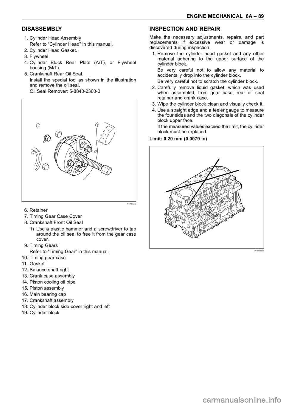
5. Crankshaft Rear Oil Seal.
Install the special tool as shown in the illustration
and remove the oil seal.
Oil Seal Remover: 5-8840-2360-0
6. Retainer
7. Timing Gear Case Cover
8. Crankshaft Front Oil Seal
1) Use a plastic hammer and a screwdriver to tap
around the oil seal to free it from the gear case
cover.
9. Timing Gears
Refer to “Timing Gear” in this manual.
10. Timing gear case
11 . G a s k e t
12. Balance shaft right
13. Crank case assembly
14. Piston cooling oil pipe
15. Piston assembly
16. Main bearing cap
17. Crankshaft assembly
18. Cylinder block side cover right and left
19. Cylinder block
INSPECTION AND REPAIR
Make the necessary adjustments, repairs, and part
replacements if excessive wear or damage is
discovered during inspection.
1. Remove the cylinder head gasket and any other
material adhering to the upper surface of the
cylinder block.
Be very careful not to allow any material to
accidentally drop into the cylinder block.
Be very careful not to scratch the cylinder block.
2. Carefully remove liquid gasket, which was used
when assembled, from gear case, rear oil seal
retainer and crank case.
3. Wipe the cylinder block clean and visually check it.
4. Use a straight edge and a feeler gauge to measure
the four sides and the two diagonals of the cylinder
block upper face.
If the measured values exceed the limit, the cylinder
block must be replaced.
Limit: 0.20 mm (0.0079 in)
015RV002
012RW122
Page 5364 of 6000
ENGINE MECHANICAL 6A – 91
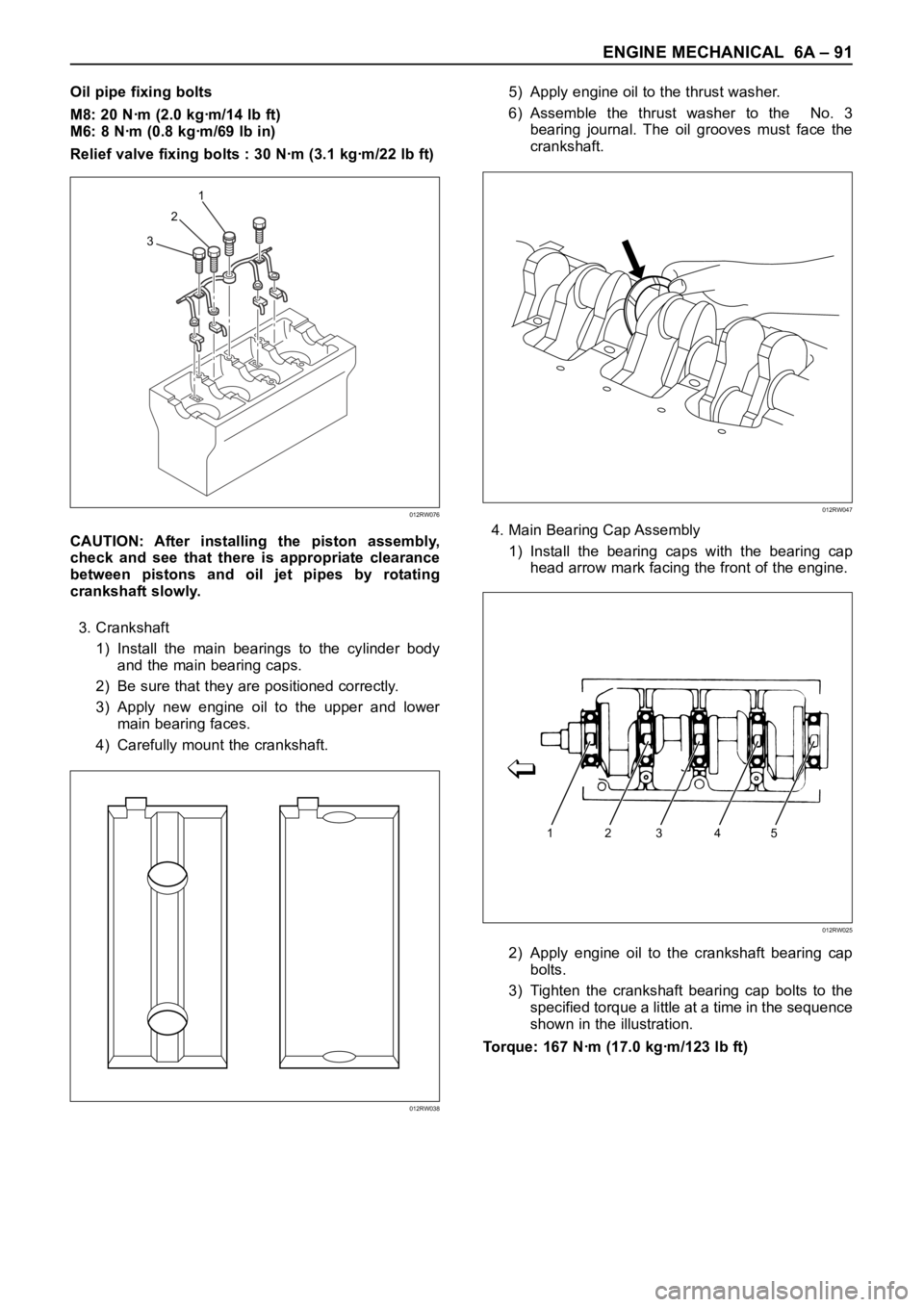
Oil pipe fixing bolts
M8: 20 Nꞏm (2.0 kgꞏm/14 lb ft)
M6: 8 Nꞏm (0.8 kgꞏm/69 lb in)
Relief valve fixing bolts : 30 Nꞏm (3.1 kgꞏm/22 lb ft)
CAUTION: After installing the piston assembly,
check and see that there is appropriate clearance
between pistons and oil jet pipes by rotating
crankshaft slowly.
3. Crankshaft
1) Install the main bearings to the cylinder body
and the main bearing caps.
2) Be sure that they are positioned correctly.
3) Apply new engine oil to the upper and lower
main bearing faces.
4) Carefully mount the crankshaft.5) Apply engine oil to the thrust washer.
6) Assemble the thrust washer to the No. 3
bearing journal. The oil grooves must face the
crankshaft.
4. Main Bearing Cap Assembly
1) Install the bearing caps with the bearing cap
head arrow mark facing the front of the engine.
2) Apply engine oil to the crankshaft bearing cap
bolts.
3) Tighten the crankshaft bearing cap bolts to the
specified torque a little at a time in the sequence
shown in the illustration.
Torque: 167 Nꞏm (17.0 kgꞏm/123 lb ft)
321
012RW076
012RW038
012RW047
12345
012RW025
Page 5365 of 6000
6A – 92 ENGINE MECHANICAL
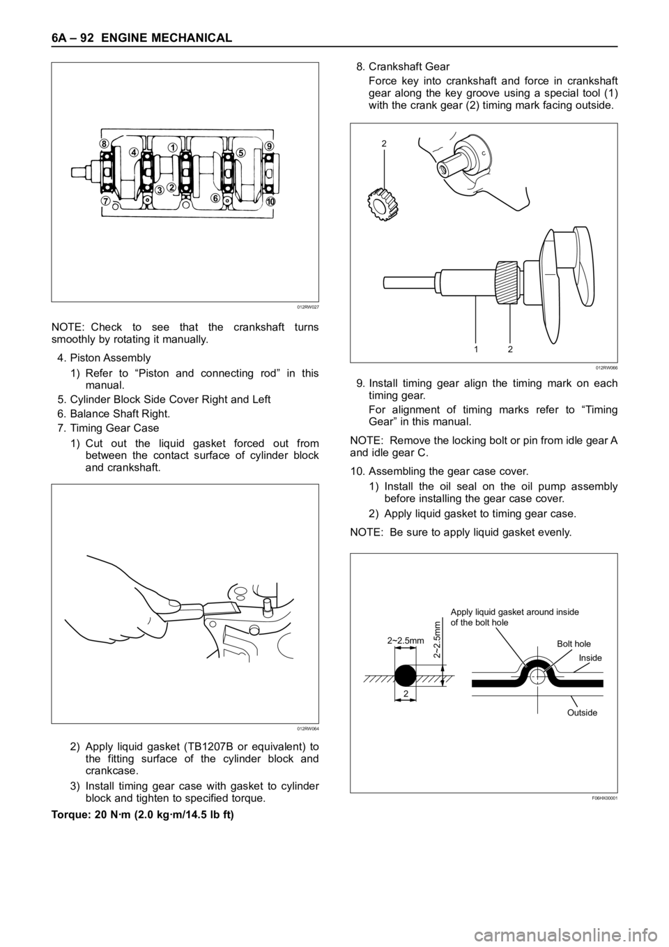
NOTE: Check to see that the crankshaft turns
smoothly by rotating it manually.
4. Piston Assembly
1) Refer to “Piston and connecting rod” in this
manual.
5. Cylinder Block Side Cover Right and Left
6. Balance Shaft Right.
7. Timing Gear Case
1) Cut out the liquid gasket forced out from
between the contact surface of cylinder block
and crankshaft.
2) Apply liquid gasket (TB1207B or equivalent) to
the fitting surface of the cylinder block and
crankcase.
3) Install timing gear case with gasket to cylinder
block and tighten to specified torque.
Torque: 20 Nꞏm (2.0 kgꞏm/14.5 lb ft)8. Crankshaft Gear
Force key into crankshaft and force in crankshaft
gear along the key groove using a special tool (1)
with the crank gear (2) timing mark facing outside.
9. Install timing gear align the timing mark on each
timing gear.
For alignment of timing marks refer to “Timing
Gear” in this manual.
NOTE: Remove the locking bolt or pin from idle gear A
and idle gear C.
10. Assembling the gear case cover.
1) Install the oil seal on the oil pump assembly
before installing the gear case cover.
2) Apply liquid gasket to timing gear case.
NOTE: Be sure to apply liquid gasket evenly.
84159
610
237
012RW027
012RW064
12
2
012RW066
2
2~2.5mm
2~2.5mm
Apply liquid gasket around inside
of the bolt hole
Bolt hole
Inside
Outside
F06HX00001
Page 5366 of 6000
ENGINE MECHANICAL 6A – 93
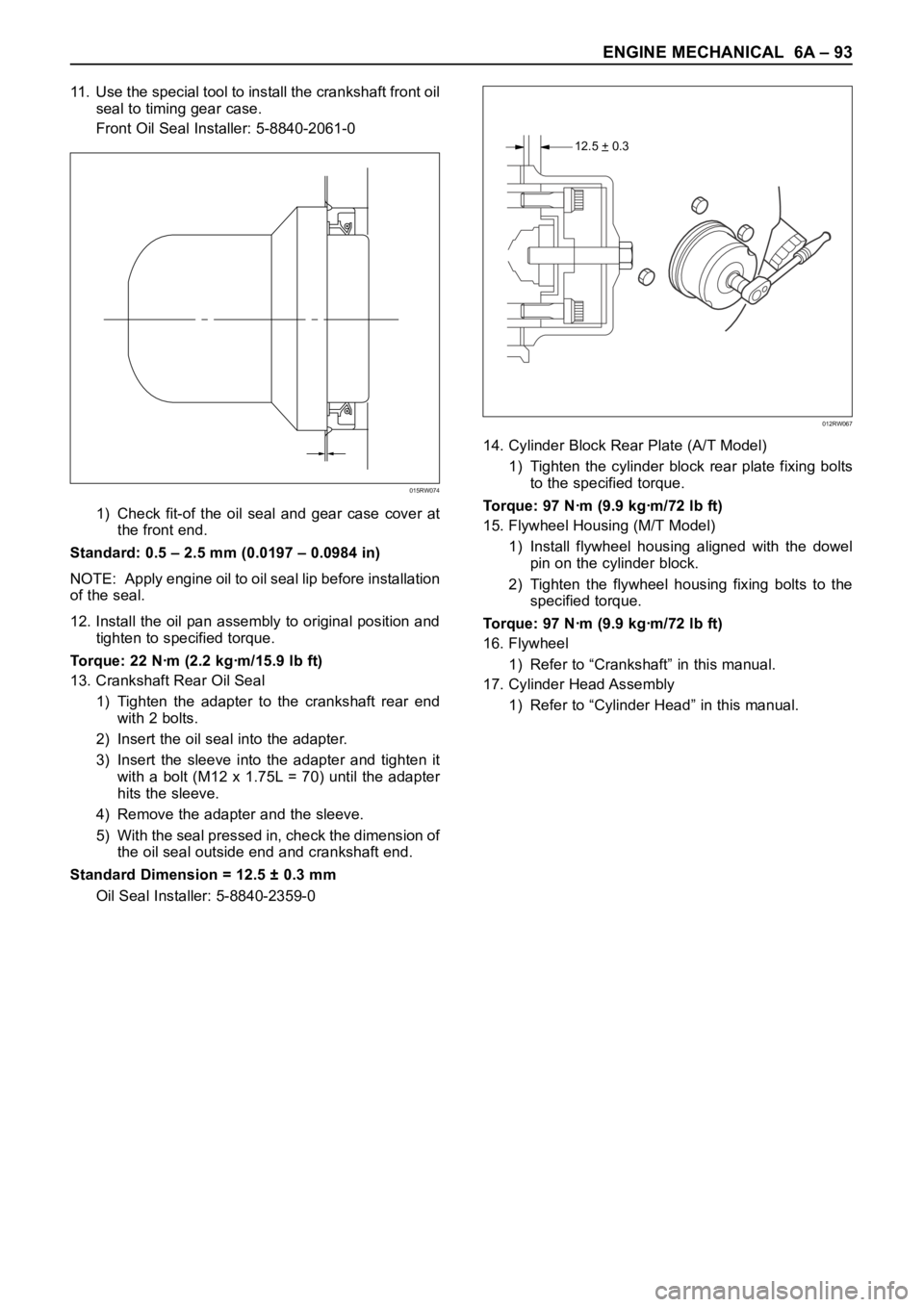
11. Use the special tool to install the crankshaft front oil
seal to timing gear case.
Front Oil Seal Installer: 5-8840-2061-0
1) Check fit-of the oil seal and gear case cover at
the front end.
Standard: 0.5 – 2.5 mm (0.0197 – 0.0984 in)
NOTE: Apply engine oil to oil seal lip before installation
of the seal.
12. Install the oil pan assembly to original position and
tighten to specified torque.
Torque: 22 Nꞏm (2.2 kgꞏm/15.9 lb ft)
13. Crankshaft Rear Oil Seal
1) Tighten the adapter to the crankshaft rear end
with 2 bolts.
2) Insert the oil seal into the adapter.
3) Insert the sleeve into the adapter and tighten it
with a bolt (M12 x 1.75L = 70) until the adapter
hits the sleeve.
4) Remove the adapter and the sleeve.
5) With the seal pressed in, check the dimension of
the oil seal outside end and crankshaft end.
Standard Dimension = 12.5 ± 0.3 mm
Oil Seal Installer: 5-8840-2359-014. Cylinder Block Rear Plate (A/T Model)
1) Tighten the cylinder block rear plate fixing bolts
to the specified torque.
Torque: 97 Nꞏm (9.9 kgꞏm/72 lb ft)
15. Flywheel Housing (M/T Model)
1) Install flywheel housing aligned with the dowel
pin on the cylinder block.
2) Tighten the flywheel housing fixing bolts to the
specified torque.
Torque: 97 Nꞏm (9.9 kgꞏm/72 lb ft)
16. Flywheel
1) Refer to “Crankshaft” in this manual.
17. Cylinder Head Assembly
1) Refer to “Cylinder Head” in this manual.
015RW074
12.5 + 0.3–
012RW067
Page 5368 of 6000
ENGINE MECHANICAL 6A – 95
OIL COOLER
1
2
050RW009
Legend
(1) Oil Cooler Assembly
(2) Oil Filter Cartridge
OIL FILTER CARTRIDGE
REMOVAL
1. Place a receptacle beneath the oil filter to contain
the drained oil.
2. Remove the oil filter cartridge using filter wrench.
Filter wrench : 5-8840-0203-0
INSTALLATION
1, Lightly apply oil to the O-ring of oil filter cartridge.
2. Turn the new oil filter cartridge by hand until the
sealing face is fitted against the O-ring.
3. Use the filter wrench to turn the oil filter an
additional one and 1/8 turns.
4. Start the engine and check for oil leakage from oil
filter.
Page 5369 of 6000

6A – 96 ENGINE MECHANICAL
REMOVAL
1. Disconnect battery ground cable
2. Drain engine coolant
3. Remove front exhaust pipe
4. Remove heat protector
5. Remove exhaust valve assembly
6. Oil cooler assembly
1) Remove water hoses from inlet and outlet pipe.
2) Put rag beneath side of oil cooler to prevent oil
leaking.
3) Remove fixing bolts and oil cooler assembly.
INSTALLATION
1. Oil Cooler
1) Tighten oil cooler fixing bolt to the specified
torque and connect water hose.
Torque: 29 Nꞏm (3.0 kgꞏm/22 lb ft)
2. Exh. Valve Assembly
1) Install exhaust valve assembly with gasket and
tighten fixing bolts to the specified torque.
Torque: 27 Nꞏm (2.7 kgꞏm/20 lb ft)
3. Heat Protector
4. Front Exhaust Pipe
1) Install front exhaust pipe and tighten fixing bolts
to the specified torque.
Exh. Valve Side: 67 Nꞏm (6.8 kgꞏm/50 lb ft)
Intermediate Pipe Side: 43 Nꞏm (4.4 kgꞏm/32 lb ft)
5. Fill engine coolant.
6. Connect battery ground cable.
7. Start engine and check for oil and water leakage
carefully.