1998 NISSAN PICK-UP Ignition
[x] Cancel search: IgnitionPage 81 of 1659

Diagnostic Procedure 13 (Warning lamp
stays on when ignition switch is turned ON.)
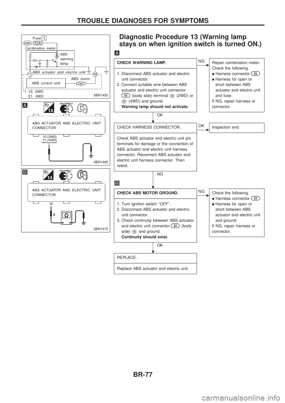
CHECK WARNING LAMP.
-------------------------------------------------------------------------------------------------------------------------------------------------------------------------------------------------------------------------------------------------------------------------------------------------------------
1. Disconnect ABS actuator and electric
unit connector.
2. Connect suitable wire between ABS
actuator and electric unit connector
E4(body side) terminalV10(2WD) or
V21(4WD) and ground.
Warning lamp should not activate.
OK
cNG
Repair combination meter.
Check the following.
lHarness connectorE4
lHarness for open or
short between ABS
actuator and electric unit
and fuse
If NG, repair harness or
connector.
CHECK HARNESS CONNECTOR.
-------------------------------------------------------------------------------------------------------------------------------------------------------------------------------------------------------------------------------------------------------------------------------------------------------------
Check ABS actuator and electric unit pin
terminals for damage or the connection of
ABS actuator and electric unit harness
connector. Reconnect ABS actuator and
electric unit harness connector. Then
retest.
NG
cOK
Inspection end
CHECK ABS MOTOR GROUND.
-------------------------------------------------------------------------------------------------------------------------------------------------------------------------------------------------------------------------------------------------------------------------------------------------------------
1. Turn ignition switch ``OFF''.
2. Disconnect ABS actuator and electric
unit connector.
3. Check continuity between ABS actuator
and electric unit connector
E4(body
side)
V16and ground.
Continuity should exist.
OK
cNG
Check the following.
lHarness connectorE4
lHarness for open or
short between ABS
actuator and electric unit
and ground
If NG, repair harness or
connector.
REPLACE.
-------------------------------------------------------------------------------------------------------------------------------------------------------------------------------------------------------------------------------------------------------------------------------------------------------------
Replace ABS actuator and electric unit.
SBR145E
SBR146E
SBR147E
.
.
.
TROUBLE DIAGNOSES FOR SYMPTOMS
BR-77
Page 150 of 1659

ENGINE CONTROL SYSTEM
SECTION
EC
CONTENTS
DIAGNOSTIC TROUBLE CODE INDEX................... 1
Alphabetical & Numerical Index for DTC
(KA engine) ............................................................ 1
PRECAUTIONS AND PREPARATION..................... 2
Special Service Tools ............................................ 2
Commercial Service Tool....................................... 4
Supplemental Restraint System (SRS) ``AIR
BAG'' (4WD models).............................................. 4
Supplemental Restraint System (SRS) ``AIR
BAG'' (2WD models).............................................. 4
KA
PRECAUTIONS AND PREPARATION..................... 5
Engine Fuel & Emission Control System .............. 5
Precautions ............................................................ 6
ENGINE AND EMISSION CONTROL OVERALL
SYSTEM..................................................................... 8
Circuit Diagram ...................................................... 8
System Diagram .................................................... 9
ECCS Component Parts Location ....................... 10
Vacuum Hose Drawing ........................................ 12
System Chart ....................................................... 13
ENGINE AND EMISSION BASIC CONTROL
SYSTEM DESCRIPTION..................................... 14
Multiport Fuel Injection (MFI) System.................. 14
Distributor Ignition (DI) System............................ 17
Air Conditioning Cut Control ................................ 18
Fuel Cut Control (at no load & high engine
speed) .................................................................. 18
EVAPORATIVE EMISSION SYSTEM..................... 19
Description ........................................................... 19
Inspection ............................................................. 19POSITIVE CRANKCASE VENTILATION................ 21
Description ........................................................... 21
Inspection ............................................................. 21
BASIC SERVICE PROCEDURE............................. 22
Fuel Pressure Release ........................................ 22
Fuel Pressure Check ........................................... 22
Injector Removal and Installation ........................ 23
Fast Idle Cam (FIC) Inspection and
Adjustment ........................................................... 24
Idle Speed/Ignition Timing/Idle Mixture Ratio
Adjustment ........................................................... 25
ON BOARD DIAGNOSTIC SYSTEM
DESCRIPTION......................................................... 36
Introduction .......................................................... 36
Diagnostic Trouble Code (DTC) .......................... 36
Malfunction Indicator Lamp (MIL) ........................ 38
CONSULT ............................................................ 45
TROUBLE DIAGNOSIS - Introduction.................. 54
Introduction .......................................................... 54
Diagnostic Worksheet .......................................... 54
TROUBLE DIAGNOSIS - Work Flow..................... 56
Work Flow ............................................................ 56
Description for Work Flow ................................... 57
TROUBLE DIAGNOSIS - Basic Inspection.......... 58
Basic Inspection ................................................... 58
TROUBLE DIAGNOSIS - General Description..... 61
Fail-Safe Chart ..................................................... 61
Symptom Matrix Chart ......................................... 62
CONSULT Reference Value in Data Monitor
Mode .................................................................... 64
Major Sensor Reference Graph in Data
Monitor Mode ....................................................... 66
ECM Terminals and Reference Value ................. 68
EC
Page 151 of 1659

TROUBLE DIAGNOSIS FOR POWER SUPPLY.... 75
Main Power Supply and Ground Circuit .............. 75
TROUBLE DIAGNOSIS FOR ``CAMSHAFT
POSI SEN'' (DTC 11).............................................. 82
Camshaft Position Sensor (CMPS) ..................... 82
TROUBLE DIAGNOSIS FOR ``MASS AIR
FLOW SEN'' (DTC 12)............................................ 89
Mass Air Flow Sensor (MAFS) ............................ 89
TROUBLE DIAGNOSIS FOR ``COOLANT TEMP
SEN'' (DTC 13)........................................................ 95
Engine Coolant Temperature Sensor (ECTS) ..... 95
TROUBLE DIAGNOSIS FOR ``IGN SIGNAL-
PRIMARY'' (DTC 21)............................................... 99
Ignition Signal ...................................................... 99
TROUBLE DIAGNOSIS FOR ``OVER HEAT''
(DTC 28)................................................................. 106
Overheat ............................................................ 106
TROUBLE DIAGNOSIS FOR ``INT AIR TEMP
SEN'' (DTC 41)...................................................... 109
Intake Air Temperature Sensor ......................... 109
TROUBLE DIAGNOSIS FOR ``THROTTLE POSI
SEN'' (DTC 43)...................................................... 113
Throttle Position Sensor .................................... 113
TROUBLE DIAGNOSIS FOR
NON-DETECTABLE ITEMS.................................. 118
Vehicle Speed Sensor (VSS) ............................ 118
Heated Oxygen Sensor (HO2S)
- LHD Models - .................................................. 123
Heated Oxygen Sensor Heater
- LHD Models - .................................................. 127
Idle Air Control Valve (IACV) - Auxiliary Air
Control (AAC) Valve .......................................... 131
Neutral Position Switch ...................................... 136
EVAP Canister Purge Control Solenoid Valve .. 140
Injector ............................................................... 144
Start Signal ........................................................ 149
Fuel Pump.......................................................... 151
Power Steering Oil Pressure Switch ................. 157
Swirl Control Valve Control Solenoid Valve ...... 161
IACV-FICD Solenoid Valve ................................ 168
MIL & Data Link Connectors ............................. 173
TD
INJECTION SYSTEM............................................ 176
Fuel System ....................................................... 176
INJECTION PUMP................................................. 178
Inspection ........................................................... 178
Removal ............................................................. 178
Installation and Adjustment................................ 180
Disassembly ....................................................... 183
Load Timer Adjustment...................................... 183
Start Q Adjustment Lever .................................. 184
INJECTION NOZZLE............................................. 186Removal and Installation ................................... 186
Disassembly ....................................................... 186
Inspection ........................................................... 187
Cleaning ............................................................. 187
Assembly............................................................ 189
Test and Adjustment .......................................... 189
FUEL SYSTEM CHECK........................................ 191
Bleeding Fuel System ........................................ 191
Bleeding Fuel Filter ............................................ 192
Checking Priming Pump .................................... 192
Checking Fuel Filter Switch ............................... 192
POSITIVE CRANKCASE VENTILATION.............. 193
Description ......................................................... 193
Inspection ........................................................... 193
QUICK-GLOW SYSTEM........................................ 194
Component Parts Location ................................ 194
Circuit Diagram .................................................. 195
Description ......................................................... 196
Wiring Diagram .................................................. 197
Glow Control Unit Circuit Inspection (For Cold
Areas)................................................................. 203
Glow Control Unit Circuit Inspection (Except
for Cold Areas)................................................... 206
Component Inspection ....................................... 208
EGR SYSTEM........................................................ 210
Component Parts Location ................................ 210
Description ......................................................... 211
Operation ........................................................... 212
Wiring Diagram .................................................. 213
System Inspection.............................................. 217
Component Inspection ....................................... 218
SOLENOID TIMER................................................ 220
Description ......................................................... 220
Operation ........................................................... 220
Wiring Diagram .................................................. 222
Inspection ........................................................... 224
FUEL CUT SYSTEM.............................................. 225
Wiring Diagram .................................................. 225
FUEL HEATER SYSTEM...................................... 226
Description ......................................................... 226
Wiring Diagram .................................................. 227
System Inspection.............................................. 228
Component Inspection ....................................... 228
FAST IDLE CONTROL CIRCUIT.......................... 230
Wiring Diagram .................................................. 230
Electrical Components Inspection ..................... 231
KA
SERVICE DATA AND SPECIFICATIONS (SDS). 232
General Specifications ....................................... 232
Inspection and Adjustment ................................ 232
Page 158 of 1659

Precautions
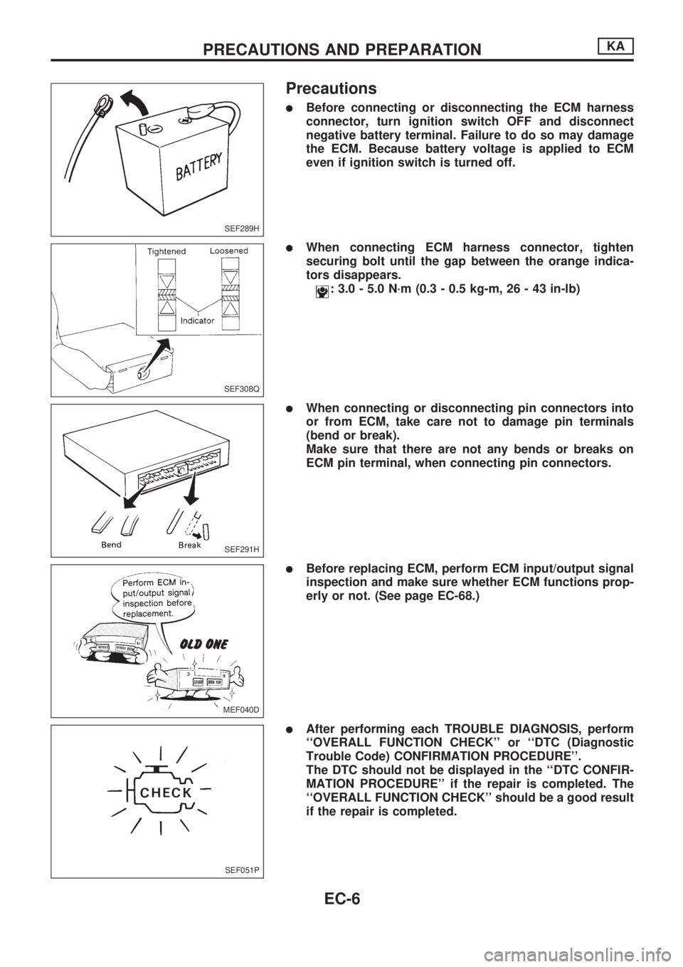
lBefore connecting or disconnecting the ECM harness
connector, turn ignition switch OFF and disconnect
negative battery terminal. Failure to do so may damage
the ECM. Because battery voltage is applied to ECM
even if ignition switch is turned off.
lWhen connecting ECM harness connector, tighten
securing bolt until the gap between the orange indica-
tors disappears.
: 3.0 - 5.0 N´m (0.3 - 0.5 kg-m, 26 - 43 in-lb)
lWhen connecting or disconnecting pin connectors into
or from ECM, take care not to damage pin terminals
(bend or break).
Make sure that there are not any bends or breaks on
ECM pin terminal, when connecting pin connectors.
lBefore replacing ECM, perform ECM input/output signal
inspection and make sure whether ECM functions prop-
erly or not. (See page EC-68.)
lAfter performing each TROUBLE DIAGNOSIS, perform
``OVERALL FUNCTION CHECK'' or ``DTC (Diagnostic
Trouble Code) CONFIRMATION PROCEDURE''.
The DTC should not be displayed in the ``DTC CONFIR-
MATION PROCEDURE'' if the repair is completed. The
``OVERALL FUNCTION CHECK'' should be a good result
if the repair is completed.
SEF289H
SEF308Q
SEF291H
MEF040D
SEF051P
PRECAUTIONS AND PREPARATIONKA
EC-6
Page 165 of 1659

System Chart
Camshaft position sensorc
ECM
(ECCS
control
module)
Mass air flow sensorc
Engine coolant temperature sensorc
Heated oxygen sensor*c
Ignition switchc
Throttle position sensorc
Neutral position switchc
Vehicle speed sensorc
Air conditioner switchc
Battery voltagec
Power steering oil pressure switchc
Intake air temperature sensorc
*: LHD models
Fuel injection &
mixture ratio controlcInjectors
Distributor ignition systemcPower transistor
Idle air control systemcIACV-AAC valve
IACV-FICD solenoid valve
Swirl control valve controlcSwirl control valve control
solenoid valve
EVAP canister controlcEVAP canister purge control
solenoid valve
Fuel pump controlcFuel pump relay
Heated oxygen sensor moni-
tor & on board diagnostic
systemcMalfunction indicator lamp
(On the instrument panel)
Acceleration cut controlcAir conditioner relay
Heated oxygen sensor
heater control*cHeated oxygen sensor
heater
ENGINE AND EMISSION CONTROL OVERALL SYSTEMKA
EC-13
Page 166 of 1659

Multiport Fuel Injection (MFI) System
INPUT/OUTPUT SIGNAL LINE
Camshaft position sensorcEngine speed and piston position
ECM
(ECCS
control
module)
cInjector
Mass air flow sensorcAmount of intake air
Engine coolant temperature sensor
cEngine coolant temperature
Heated oxygen sensor*
cDensity of oxygen in exhaust gas
Throttle position sensor
cThrottle position
Throttle valve idle position
Neutral position switch
cGear position
Vehicle speed sensor
cVehicle speed
Ignition switch
cStart signal
Battery
cBattery voltage
*: LHD models
BASIC MULTIPORT FUEL INJECTION
SYSTEM
The amount of fuel injected from the fuel injector is
determined by the ECM. The ECM controls the
length of time the valve remains open (injection
pulse duration). The amount of fuel injected is a
program value in the ECM memory. The program
value is preset by engine operating conditions.
These conditions are determined by input signals
(for engine speed and intake air) from both the
camshaft position sensor and the mass air flow
sensor.
VARIOUS FUEL INJECTION
INCREASE/DECREASE COMPENSATION
The amount of fuel injected is compensated for to
improve engine performance. This will be made
under various operating conditions as listed below.
lDuring warm-up
lWhen starting the engine
lDuring acceleration
lHot-engine operation
lHigh-load, high-speed operation
lWhen swirl control valve operates
lDuring deceleration
lDuring high-engine speed operation
lExtremely high-engine coolant temperature
ENGINE AND EMISSION BASIC CONTROL SYSTEM DESCRIPTIONKA
EC-14
Page 169 of 1659

Distributor Ignition (DI) System
INPUT/OUTPUT SIGNAL LINE
Camshaft position sensorcEngine speed and piston position
ECM
(ECCS
control
module)
cPower
transistor
Mass air flow sensorcAmount of intake air
Engine coolant temperature sensor
cEngine coolant temperature
Throttle position sensor
c
Throttle position
Throttle valve idle position
Vehicle speed sensor
cVehicle speed
Ignition switch
cStart signal
Intake air temperature sensor
cIntake air temperature
Neutral position switch
cGear position
Battery
cBattery voltage
SYSTEM DESCRIPTION
The ignition timing is controlled by the ECM to maintain the best
air-fuel ratio for every running condition of the engine.
The ignition timing data is stored in the ECM. This data forms the
map shown left.
The ECM detects information such as the injection pulse width
and camshaft position sensor signal. Responding to this
information, ignition signals are transmitted to the power transis-
tor.
e.g. N: 1,800 rpm, Tp: 1.50 msec
A ÉBTDC
During the following conditions, the ignition timing is revised by
the ECM according to the other data stored in the ECM.
1 At starting
2 During warm-up
3 At idle
4 When swirl control valve operates
5 Hot-engine operation
6 At acceleration
SEF742M
ENGINE AND EMISSION BASIC CONTROL SYSTEM DESCRIPTIONKA
EC-17
Page 170 of 1659

Air Conditioning Cut Control
INPUT/OUTPUT SIGNAL LINE
Air conditioner switchcAir conditioner ``ON'' signal
ECM
(ECCS
control
module)
cAir condi-
tioner
relayThrottle position sensorcThrottle valve opening angle
Ignition switch
cStart signal
Engine coolant temperature sensor
cEngine coolant temperature
SYSTEM DESCRIPTION
This system improves engine operation when the
air conditioner is used.
Under the following conditions, the air conditioner
is turned off.
lWhen the accelerator pedal is fully depressed
lWhen cranking the engine
lWhen the engine coolant temperature becomes
excessively high
Fuel Cut Control (at no load & high engine
speed)
INPUT/OUTPUT SIGNAL LINE
Vehicle speed sensorcVehicle speed
ECM
(ECCS
control
module)
cInjectors
Neutral position switchcNeutral position
Throttle position sensor
cThrottle position
Engine coolant temperature sensor
cEngine coolant temperature
Camshaft position sensor
cEngine speed
If the engine speed is above 3,500 rpm with no load (for
example, in neutral and engine speed over 3,500 rpm) fuel will
be cut off after some time. The exact time when the fuel is cut
off varies based on engine speed.
Fuel cut will operate until the engine speed reaches 1,500 rpm,
then fuel cut is cancelled.
NOTE:
This function is different than deceleration control listed
under multiport fuel injection on EC-14.
ENGINE AND EMISSION BASIC CONTROL SYSTEM DESCRIPTIONKA
EC-18