Page 39 of 54
Disassembly
1. Remove side bearing inner cone with Tool. For removal
procedure, refer to ordinary differential case.
2. Loosen ring gear bolts in a criss-cross pattern.
3. Tap ring gear off the gear with a soft hammer.
4. Put marks on both differential cases.
5. Loosen screws on differential cases A and B using a press.
Tool number: ST33081000
6. Separate differential cases A and B.
7. Drive out pinion mate shaft lock pin with Tool.
Draw out component parts.
SPD839
SPD449A
SPD841
DIFFERENTIAL LOCK
PD-38
Page 40 of 54
Inspection
CONTACT SURFACES
1. Clean the disassembled parts in suitable solvent and blow dry
with compressed air.
2. If following surfaces are found with burrs or scratches, smooth
with oil stone.
V1Differential case A
V2Differential case B
V3Side gear thrust washer
V4Side gear
V5Pinion mate thrust washer
V6Pinion mate gear
V7Pinion mate shaft
ACTUATOR OPERATION
Apply a vacuum pressure of 66.7 kPa (667 mbar, 500 mmHg, 19.69
inHg) and check its operation and leakage within 10 seconds.
SPD842
SPD906
DIFFERENTIAL LOCK
PD-39
Page 41 of 54

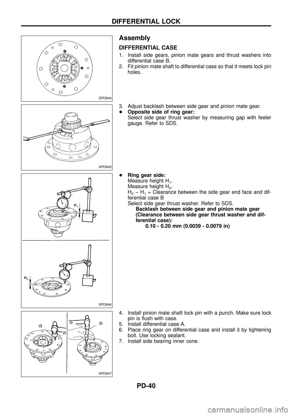
Assembly
DIFFERENTIAL CASE
1. Install side gears, pinion mate gears and thrust washers into
differential case B.
2. Fit pinion mate shaft to differential case so that it meets lock pin
holes.
3. Adjust backlash between side gear and pinion mate gear.
+Opposite side of ring gear:
Select side gear thrust washer by measuring gap with feeler
gauge. Refer to SDS.
+Ring gear side:
Measure height H
1.
Measure height H
2.
H
2þH1= Clearance between the side gear end face and dif-
ferential case B
Select side gear thrust washer. Refer to SDS.
Backlash between side gear and pinion mate gear
(Clearance between side gear thrust washer and dif-
ferential case):
0.10 - 0.20 mm (0.0039 - 0.0079 in)
4. Install pinion mate shaft lock pin with a punch. Make sure lock
pin is ¯ush with case.
5. Install differential case A.
6. Place ring gear on differential case and install it by tightening
bolt. Use locking sealant.
7. Install side bearing inner cone.
SPD844
SPD845
SPD846
SPD847
DIFFERENTIAL LOCK
PD-40
Page 42 of 54
ACTUATOR
+If same differential carrier is used again, reuse actuator shim or
use a shim of the same thickness when used shim is damaged.
+When differential carrier is replaced with a new one, select
actuator shim to keep differential lock mechanism functioning.
+When installing the differential lock fork, make sure it is facing
the correct direction.
1. Standard length ``A'' is between speci®ed mounting surface of
actuator and differential case B surface ``P''. Refer to SDS.
2. Install differential carrier on axle case.
3. Rotate ring gear until surface ``P'' is seen through actuator
mounting hole in axle case.
Measure dimension ``L'' between actual mounting surface of
actuator on axle case and surface ``P'', using suitable gauge
tool.
+Put gauge as shown on drawing.
+Put mark on gauge at actuator mounting surface.
+Measure dimension ``L''.
SPD848
SPD930
SPD931
DIFFERENTIAL LOCK
Assembly (Cont'd)
PD-41
Page 43 of 54
4. If shim thickness determined by equation is assumed as ``T'',
``T'' will be expressed by equation ``A'' - ``L''. Select a combina-
tion of shims from those shown in SDS so that shim thickness
is within ``T'' range. Install actuator using selected shims.
SPD932
DIFFERENTIAL LOCK
Assembly (Cont'd)
PD-42
Page 44 of 54
System Description
The differential lock operates only in 4WD.
The differential lock control unit interrupts current ¯owing through
differential lock solenoid-2 when vehicle speed exceeds 7 km/h (4
MPH). If the differential lock switch is accidentally turned on when
vehicle speed is greater than 7 km/h (4 MPH), the control unit will
prevent the differential lock from sustaining impact damage.
A warning buzzer will sound when the vehicle is driven over 20
km/h (12 MPH) with the differential lock engaged.
SPD446A
DIFFERENTIAL LOCK
PD-43
Page 45 of 54
Component Parts Location
SPD442A
DIFFERENTIAL LOCK
PD-44
Page 46 of 54
Wiring Diagram Ð DIFF/L Ð/LHD Models
TPD013
DIFFERENTIAL LOCK
PD-45