Page 20 of 54
Ring Gear and Drive Pinion
Check gear teeth for scoring, cracking or chipping. If any damaged
part is evident, replace ring gear and drive pinion as a set (hypoid
gear set).
Differential Case Assembly
Check mating surfaces of differential case, side gears, pinion mate
gears, pinion mate shaft, thrust block and thrust washers.
Bearing
1. Thoroughly clean bearing.
2. Check bearings for wear, scratches, pitting or ¯aking.
Check tapered roller bearing for smooth rotation. If damaged,
replace outer race and inner cone as a set.
SPD530
SPD717
SPD715
INSPECTION
PD-19
Page 28 of 54
To avoid confusion while calculating bearing shims, it is absolutely
necessary to stay with the metric system. If you measure anything
in inches,the results must be converted to the metric system.
Drive Pinion Height
1. First prepare Tools for pinion height adjustment.
:
V1Height gauge (ST31251000)
V2Dummy shaft (ST31181001)
V3Spacer [thickness: 2.50 mm (0.0984 in)]
V4Feeler gauge
2. To simplify the job, make a chart, like the one below, to orga-
nize your calculations.
LETTERSHUNDREDTHS OF
A MILLIMETER
H: Head number
D¢: Figure marked on dummy shaft
S: Figure marked on height gauge
N: Measuring clearance
3. Write the following numbers down the chart.
H: Head number
D¢: Figure marked on dummy shaft.
SPD758
SPD542
SPD759
ADJUSTMENT
PD-27
Page 29 of 54
S: Figure marked on height gauge.
4. Place pinion rear bearing inner cone and Tools on gear carrier.
Tool number:
ST31181001
5. Attach Tool (Height gauge) to gear carrier, and measure the
clearance between the height gauge tip and the dummy shaft
face.
Tool number:
ST31251000
6. Substitute these values into the equation to calculate the thick-
ness of the washer.
If values signifying H, D¢and S are not given, regard them as
zero and calculate.
T (Thickness of washer)
=Nþ[(HþD¢þ S) x 0.01] + 3.05
SPD760
SPD271-A
SPD272-A
PD444-A
PD029
ADJUSTMENT
Drive Pinion Height (Cont'd)
PD-28
Page 39 of 54
Disassembly
1. Remove side bearing inner cone with Tool. For removal
procedure, refer to ordinary differential case.
2. Loosen ring gear bolts in a criss-cross pattern.
3. Tap ring gear off the gear with a soft hammer.
4. Put marks on both differential cases.
5. Loosen screws on differential cases A and B using a press.
Tool number: ST33081000
6. Separate differential cases A and B.
7. Drive out pinion mate shaft lock pin with Tool.
Draw out component parts.
SPD839
SPD449A
SPD841
DIFFERENTIAL LOCK
PD-38
Page 53 of 54

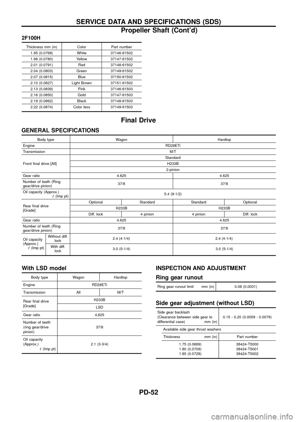
2F100H
Thickness mm (in) Color Part number1.95 (0.0768) White 37146-61502
1.98 (0.0780) Yellow 37147-61502
2.01 (0.0791) Red 37148-61502
2.04 (0.0803) Green 37149-61502
2.07 (0.0815) Blue 37150-61502
2.10 (0.0827) Light Brown 37151-61502
2.13 (0.0839) Pink 37146-61503
2.16 (0.0850) Gold 37147-61503
2.19 (0.0862) Black 37148-61503
2.22 (0.0874) Color less 37149-61503
Final Drive
GENERAL SPECIFICATIONS
Body type Wagon Hardtop
Engine RD28ETi
Transmission M/T
Front ®nal drive [All] Standard
H233B
2-pinion
Gear ratio 4.625 4.625
Number of teeth (Ring
gear/drive pinion) 37/8 37/8
Oil capacity (Approx.) !(Imp pt) 5.4 (9-1/2)
Rear ®nal drive
[Grade] Optional Standard Standard Optional
H233B H233B
Diff. lock 4 pinion 4 pinion Diff. lock
Gear ratio 4.625 4.625
Number of teeth (Ring
gear/drive pinion) 37/8 37/8
Oil capacity
(Approx.) !(Imp pt) Without diff.
lock 2.4 (4
-1/4)2.4 (4-1/4)
With diff.lock 3.0 (5-1/4) 3.0 (5-1/4)
With LSD model
Body type Wagon Hardtop
Engine RD28ETi
Transmission All M/T
Rear ®nal drive
[Grade] H233B
LSD
Gear ratio 4,625
Number of teeth
(ring gear/drive
pinion) 37/8
Oil capacity
(Approx.) !(Imp pt) 2.1 (3-3/4)
INSPECTION AND ADJUSTMENT
Ring gear runout
Ring gear runout limit mm (in) 0.08 (0.0031)
Side gear adjustment (without LSD)
Side gear backlash
(Clearance between side gear to
differential case) mm (in) 0.15 - 0.20 (0.0059 - 0.0079)
Available side gear thrust washers
Thickness mm (in) Part number 1.75 (0.0689)
1.80 (0.0709)
1.85 (0.0728) 38424-T5000
38424-T5001
38424-T5002
SERVICE DATA AND SPECIFICATIONS (SDS)
Propeller Shaft (Cont'd)
PD-52