Page 14 of 47
Harness indication
+Letter designations next to test meter probe indicate harness
(connector) wire color.
+Connector numbers in a single circle
M33indicate harness con-
nectors.
Component indication
+Connector numbers in a double circle indicate component con-
nectors.
SWITCH POSITIONS
Switches are shown in wiring diagrams as if the vehicle is in the
``normal'' condition.
A vehicle is in the ``normal'' condition when:
+ignition switch is ``OFF'',
+doors, hood and trunk lid/back door are closed,
+pedals are not depressed, and
+parking brake is released.
AGI070
SGI860
HOW TO READ WIRING DIAGRAMS
Description (Cont'd)
GI-13
Page 33 of 47

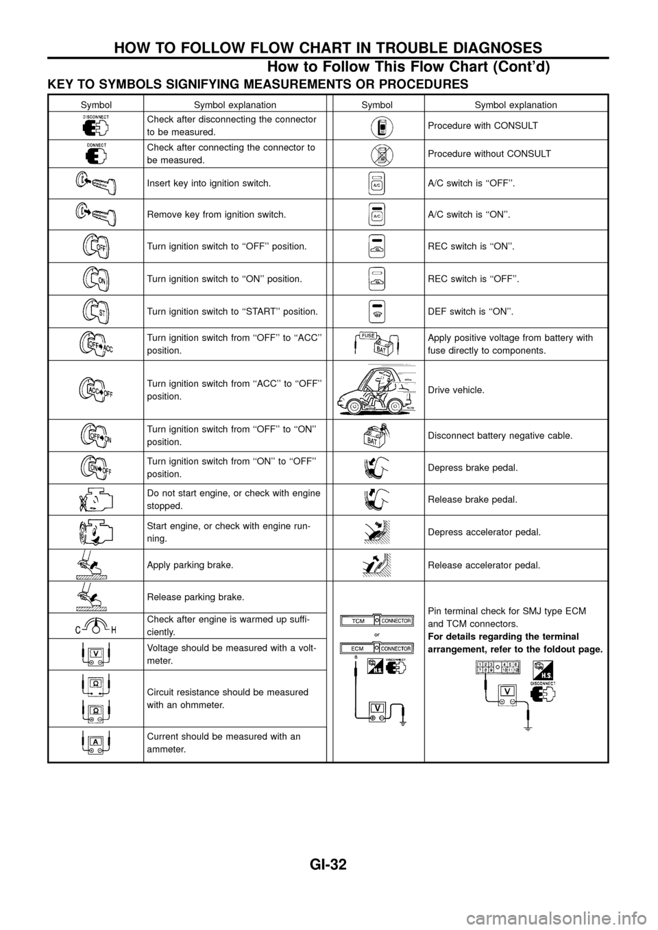
KEY TO SYMBOLS SIGNIFYING MEASUREMENTS OR PROCEDURES
Symbol Symbol explanation Symbol Symbol explanation
Check after disconnecting the connector
to be measured.Procedure with CONSULT
Check after connecting the connector to
be measured.Procedure without CONSULT
Insert key into ignition switch.A/C switch is ``OFF''.
Remove key from ignition switch.A/C switch is ``ON''.
Turn ignition switch to ``OFF'' position.REC switch is ``ON''.
Turn ignition switch to ``ON'' position.REC switch is ``OFF''.
Turn ignition switch to ``START'' position.DEF switch is ``ON''.
Turn ignition switch from ``OFF'' to ``ACC''
position.Apply positive voltage from battery with
fuse directly to components.
Turn ignition switch from ``ACC'' to ``OFF''
position.Drive vehicle.
Turn ignition switch from ``OFF'' to ``ON''
position.Disconnect battery negative cable.
Turn ignition switch from ``ON'' to ``OFF''
position.Depress brake pedal.
Do not start engine, or check with engine
stopped.Release brake pedal.
Start engine, or check with engine run-
ning.Depress accelerator pedal.
Apply parking brake.Release accelerator pedal.
Release parking brake.
Pin terminal check for SMJ type ECM
and TCM connectors.
For details regarding the terminal
arrangement, refer to the foldout page.Check after engine is warmed up suffi-
ciently.
Voltage should be measured with a volt-
meter.
Circuit resistance should be measured
with an ohmmeter.
Current should be measured with an
ammeter.
HOW TO FOLLOW FLOW CHART IN TROUBLE DIAGNOSES
How to Follow This Flow Chart (Cont'd)
GI-32
Page 42 of 47

Tow Truck Towing
CAUTION:
+All applicable local laws regarding the towing operation
must be obeyed.
+It is necessary to use proper towing equipment to avoid
possible damage to the vehicle during a towing operation.
+Attach safety chains for all towing.
+When towing, make sure that the transmission, steering
system and power train are in good order. If any unit is
damaged, a dolly must be used.
+When towing with the front wheels on the ground:
Turn the ignition key to the ``OFF'' position and secure the
steering wheel in a straight-ahead position with a rope or
similar device. Never place the ignition key in the ``LOCK''
position. This will result in damage to the steering lock
mechanism.
+When towing manual transmission models with the rear
wheels on the ground:
Release the parking brake and move the gearshift lever to
neutral (``N'' position).
+For 4-wheel drive models:
Set the manual-lock free-running hubs to the free position and
2-way lock free-running hubs to the auto position. (See
``
Transfer case shifting procedures for 4-wheel drive
vehicles'' in ``Starting and driving'' section.) Move the transfer
case shift lever into the ``2H'' position and the transmission shift
lever into the neutral (``N'') position.
Do not shift the transfer lever to the ``4L'' position. This will
cause damage to the transmission.
NISSAN recommends that a dolly be used as illustrated.
If you have to tow a manual transmission model with front
wheels raised (with rear wheels on ground)
Observe the following restricted raising heights.
+Do not raise the front end over!.
Wagon
!= 600 mm (23.62 in)
Hardtop
!= 500 mm (19.69 in)
SGI023A
SGI024A
LIFTING POINTS AND TOW TRUCK TOWING
GI-41