Page 4 of 29

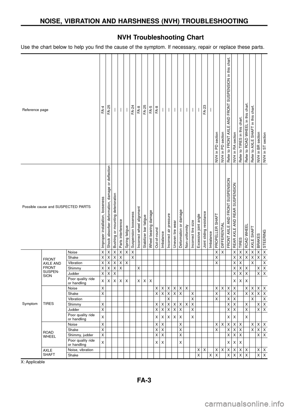
NVH Troubleshooting Chart
Use the chart below to help you ®nd the cause of the symptom. If necessary, repair or replace these parts.
Reference pageFA-4
FA-25
Ð
Ð
Ð
FA-24
FA-8
FA-25
FA-5
FA-8
Ð
Ð
Ð
Ð
Ð
Ð
Ð
FA-23
Ð
NVH in PD section
NVH in PD section
Refer to FRONT AXLE AND FRONT SUSPENSION in this chart.
NVH in RA section
Refer to TIRES in this chart.
Refer to ROAD WHEEL in this chart.
Refer to AXLE SHAFT in this chart.
NVH in BR section
NVH in ST section
Possible cause and SUSPECTED PARTS
Improper installation, looseness
Shock absorber deformation, damage or de¯ection
Bushing or mounting deterioration
Parts interference
Spring fatigue
Suspension looseness
Incorrect wheel alignment
Stabilizer bar fatigue
Wheel bearing damage
Out-of-round
Imbalance
Incorrect air pressure
Uneven tire wear
Deformation or damage
Non-uniformity
Incorrect tire size
Excessive joint angle
Joint sliding resistance
Imbalance
PROPELLER SHAFT
DIFFERENTIAL
FRONT AXLE AND FRONT SUSPENSION
REAR AXLE AND REAR SUSPENSION
TIRES
ROAD WHEEL
AXLE SHAFT
BRAKES
STEERING
SymptomFRONT
AXLE AND
FRONT
SUSPEN-
SIONNoiseXXXXXX XX XXXXXX
ShakeXXXX X X XXXXXX
VibrationXXXXX X XX X X
ShimmyXXXX X XXX XX
Judder X X XXXX XX
Poor quality ride
or handlingXXXXX XXX XXX
TIRESNoise XXXXXXX XXXX XXXX
Shake XXXXXX X X XX XXXX
Vibration X X X X X X X
Shimmy XXXXXXXX XX X XX
Judder XXXXXX X XX X XX
Poor quality ride
or handlingX XXXXX X XX X
ROAD
WHEELNoise X X X XXXXXX XXX
Shake X X X X X X X X X X X
Shimmy, judder X X X X X X X X X
Poor quality ride
or handlingX XX X XXX
AXLE
SHAFTNoise, vibration X XXXXXXX XX
ShakeX XX XXXX XX
X: Applicable
NOISE, VIBRATION AND HARSHNESS (NVH) TROUBLESHOOTING
FA-3
Page 13 of 29
Installation
Install free-running hub in the reverse order of removal.
Apply multi-purpose grease to bushing and drive clutch
before installing on wheel hub and axle shaft, respectively.
+Install drive clutch.
+Place snap ring in drive shaft groove.
Axial end play:
0.4 mm (0.016 in) or less
Snap ring size:
Refer to SDS.
+When installing manual-lock free-running hub, make sure the
position ``FREE''.
Apply multi-purpose grease to drive shaft end.
+Check operation of manual-lock free-running hub after install-
ing it.
Inspection
+Check that hub moves smoothly and freely.
+Check that clutch moves smoothly in the body.
SFA860B
SFA200
SFA428A
FRONT AXLE Ð Manual-lock Free-running Hub
FA-12
Page 14 of 29

Removal
1. Set the auto-lock free-running hub at the condition ``LOCK''.
2. Remove auto-lock free-running hub assembly.
3. Remove snap ring.
4. Remove spindle washer and thrust washer.
5. After installing auto-lock free-running hub, check operation of it.
When installing it, apply recommended grease to drive shaft
end.
Installation
1. When installing hub's mating parts (such as thrust washer and
spindle washer) on drive shaft, select suitable snap ring so that
end play between drive shaft and its mating parts is within
speci®cations.
Axial end play:
0.4 mm (0.016 in) or less
Snap ring size:
Refer to SDS.
2. Install auto-lock free-running hub assembly to wheel hub.
+When installing auto-lock free-running hub assembly, be sure
to align outer brake pawl with notch in spindle.
+After inserting auto-lock free-running hub assembly into bore in
wheel hub, make sure there is no clearance between hub
assembly and wheel hub. If clearance exists, the cause may be
one of the following:
(1) Hub assembly is set in ``LOCK'' position.
(2) Outer brake pawl is not aligned with notch in spindle.
SFA861B
SFA862B
SFA863B
SFA433AA
SFA864B
FRONT AXLE Ð Auto-lock Free-running Hub
FA-13