Page 32 of 65
10. Remove fuel injection tube assembly and spill tube.
11. Remove cylinder head bolts in numerical order and remove
cylinder head.
Disassembly
1. Remove following parts:
a. Thermostat housing
b. Engine slinger
c. Glow plate and glow plugs
2. Remove camshaft bracket securing nuts in numerical order
shown in ®gure in two or three stages.
To install camshaft bracket caps, tighten nuts in reverse order
of removal. Tighten in two or three stages.
3. Remove camshaft and oil seal.
4. Remove valve lifters.
5. Remove valve component parts with tool.
SEM703B
SEM714B
SEM716B
CYLINDER HEAD
Removal (Cont'd)
EM-31
Page 33 of 65

Inspection
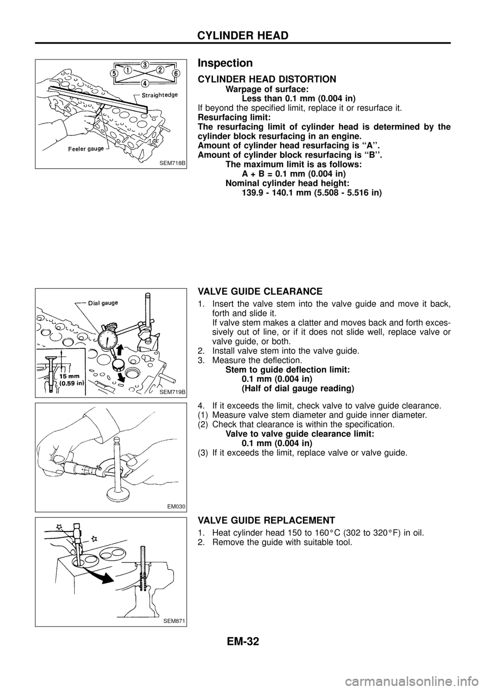
CYLINDER HEAD DISTORTION
Warpage of surface:
Less than 0.1 mm (0.004 in)
If beyond the speci®ed limit, replace it or resurface it.
Resurfacing limit:
The resurfacing limit of cylinder head is determined by the
cylinder block resurfacing in an engine.
Amount of cylinder head resurfacing is ``A''.
Amount of cylinder block resurfacing is ``B''.
The maximum limit is as follows:
A + B = 0.1 mm (0.004 in)
Nominal cylinder head height:
139.9 - 140.1 mm (5.508 - 5.516 in)
VALVE GUIDE CLEARANCE
1. Insert the valve stem into the valve guide and move it back,
forth and slide it.
If valve stem makes a clatter and moves back and forth exces-
sively out of line, or if it does not slide well, replace valve or
valve guide, or both.
2. Install valve stem into the valve guide.
3. Measure the de¯ection.
Stem to guide de¯ection limit:
0.1 mm (0.004 in)
(Half of dial gauge reading)
4. If it exceeds the limit, check valve to valve guide clearance.
(1) Measure valve stem diameter and guide inner diameter.
(2) Check that clearance is within the speci®cation.
Valve to valve guide clearance limit:
0.1 mm (0.004 in)
(3) If it exceeds the limit, replace valve or valve guide.
VALVE GUIDE REPLACEMENT
1. Heat cylinder head 150 to 160ÉC (302 to 320ÉF) in oil.
2. Remove the guide with suitable tool.
SEM718B
SEM719B
EM030
SEM871
CYLINDER HEAD
EM-32
Page 37 of 65

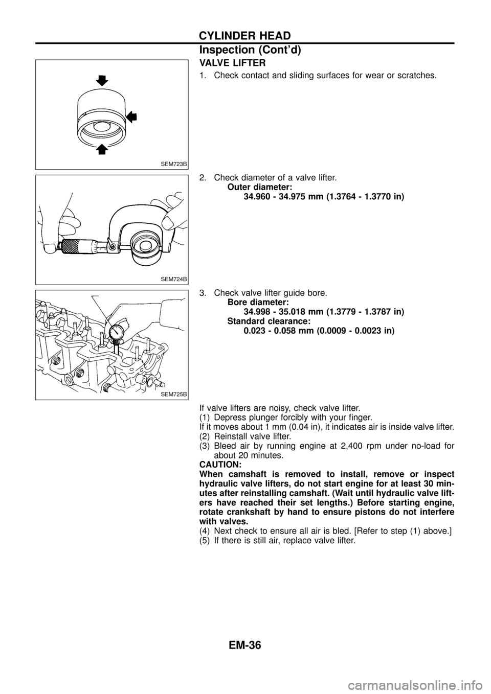
VALVE LIFTER
1. Check contact and sliding surfaces for wear or scratches.
2. Check diameter of a valve lifter.
Outer diameter:
34.960 - 34.975 mm (1.3764 - 1.3770 in)
3. Check valve lifter guide bore.
Bore diameter:
34.998 - 35.018 mm (1.3779 - 1.3787 in)
Standard clearance:
0.023 - 0.058 mm (0.0009 - 0.0023 in)
If valve lifters are noisy, check valve lifter.
(1) Depress plunger forcibly with your ®nger.
If it moves about 1 mm (0.04 in), it indicates air is inside valve lifter.
(2) Reinstall valve lifter.
(3) Bleed air by running engine at 2,400 rpm under no-load for
about 20 minutes.
CAUTION:
When camshaft is removed to install, remove or inspect
hydraulic valve lifters, do not start engine for at least 30 min-
utes after reinstalling camshaft. (Wait until hydraulic valve lift-
ers have reached their set lengths.) Before starting engine,
rotate crankshaft by hand to ensure pistons do not interfere
with valves.
(4) Next check to ensure all air is bled. [Refer to step (1) above.]
(5) If there is still air, replace valve lifter.
SEM723B
SEM724B
SEM725B
CYLINDER HEAD
Inspection (Cont'd)
EM-36
Page 39 of 65
Assembly
1. Install valve component parts.
Install valve spring with its narrow pitch side toward cylinder
head side.
a. When installing valve, apply engine oil on the valve stem
and lip of valve oil seal.
b. Check whether the valve face is free from foreign matter.
c. Install valve spring retainers on the intake side and valve
rotators on the exhaust side.
d. Valve rotators cannot be disassembled.
2. Set camshaft.
Set camshaft so that dowel pin faces up.
3. Install cam bracket caps so that front mark faces forward.
Cam bracket nut (Tighten in two or three stages):
:21-26Nzm
(2.1 - 2.7 kg-m, 15 - 20 ft-lb)
4. Apply engine oil to new oil seal and install it.
Installation
1. Install cylinder head gasket.
a. When replacing only cylinder head gasket, install same
grade gasket as the one formerly used.
b. When replacing or repairing cylinder block, cylinder head,
piston, connecting rod and crankshaft, select gasket as
follows:
SEM202
SEM731BB
SEM732B
SEM733B
CYLINDER HEAD
EM-38
Page 42 of 65

Checking
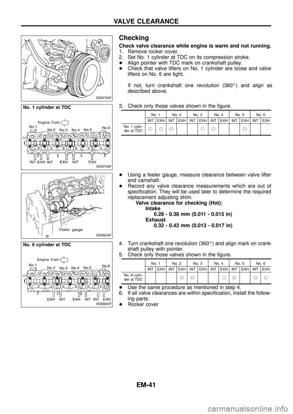
Check valve clearance while engine is warm and not running.
1. Remove rocker cover.
2. Set No. 1 cylinder at TDC on its compression stroke.
+Align pointer with TDC mark on crankshaft pulley.
+Check that valve lifters on No. 1 cylinder are loose and valve
lifters on No. 6 are tight.
If not, turn crankshaft one revolution (360É) and align as
described above.
3. Check only those valves shown in the ®gure.
No. 1 No. 2 No. 3 No. 4 No. 5 No. 6
INT EXH INT EXH INT EXH INT EXH INT EXH INT EXH
No. 1 cylin-
der at TDCjjj jj j
+Using a feeler gauge, measure clearance between valve lifter
and camshaft.
+Record any valve clearance measurements which are out of
speci®cation. They will be used later to determine the required
replacement adjusting shim.
Valve clearance for checking (Hot):
Intake
0.28 - 0.38 mm (0.011 - 0.015 in)
Exhaust
0.32 - 0.42 mm (0.013 - 0.017 in)
4. Turn crankshaft one revolution (360É) and align mark on crank-
shaft pulley with pointer.
5. Check only those valves shown in the ®gure.
No. 1 No. 2 No. 3 No. 4 No. 5 No. 6
INT EXH INT EXH INT EXH INT EXH INT EXH INT EXH
No. 6 cylin-
der at TDCjj jj jj
+Use the same procedure as mentioned in step 4.
6. If all valve clearances are within speci®cation, install the follow-
ing parts:
+Rocker cover
SEM790F
SEM799F
SEM634F
SEM800F
VALVE CLEARANCE
EM-41
Page 43 of 65

Adjusting
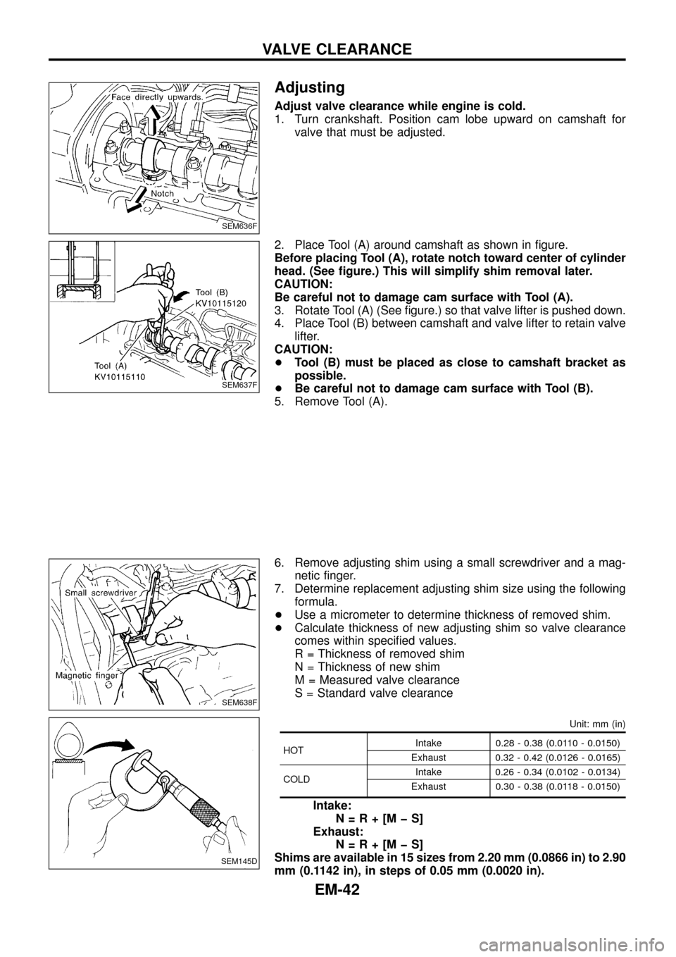
Adjust valve clearance while engine is cold.
1. Turn crankshaft. Position cam lobe upward on camshaft for
valve that must be adjusted.
2. Place Tool (A) around camshaft as shown in ®gure.
Before placing Tool (A), rotate notch toward center of cylinder
head. (See ®gure.) This will simplify shim removal later.
CAUTION:
Be careful not to damage cam surface with Tool (A).
3. Rotate Tool (A) (See ®gure.) so that valve lifter is pushed down.
4. Place Tool (B) between camshaft and valve lifter to retain valve
lifter.
CAUTION:
+Tool (B) must be placed as close to camshaft bracket as
possible.
+Be careful not to damage cam surface with Tool (B).
5. Remove Tool (A).
6. Remove adjusting shim using a small screwdriver and a mag-
netic ®nger.
7. Determine replacement adjusting shim size using the following
formula.
+Use a micrometer to determine thickness of removed shim.
+Calculate thickness of new adjusting shim so valve clearance
comes within speci®ed values.
R = Thickness of removed shim
N = Thickness of new shim
M = Measured valve clearance
S = Standard valve clearance
Unit: mm (in)
HOTIntake 0.28 - 0.38 (0.0110 - 0.0150)
Exhaust 0.32 - 0.42 (0.0126 - 0.0165)
COLDIntake 0.26 - 0.34 (0.0102 - 0.0134)
Exhaust 0.30 - 0.38 (0.0118 - 0.0150)
Intake:
N=R+[MþS]
Exhaust:
N=R+[MþS]
Shims are available in 15 sizes from 2.20 mm (0.0866 in) to 2.90
mm (0.1142 in), in steps of 0.05 mm (0.0020 in).
SEM636F
SEM637F
SEM638F
SEM145D
VALVE CLEARANCE
EM-42
Page 45 of 65
SEM433C
ENGINE REMOVAL
EM-44
Page 46 of 65
Removal
1. Remove engine, transmission and transfer's undercovers, oil
pan guard and hood.
2. Drain engine coolant.
3. Remove charge air cooler assembly.
4. Remove vacuum hoses, fuel tubes, harnesses, and connectors
and so on.
5. Remove radiator assembly.
6. Remove drive belts.
7. Remove power steering oil pump, alternator and air conditioner
compressor.
8. Remove starter motor assembly.
9. Remove front exhaust tube.
10. Remove transmission from vehicle.
Refer to MT section.
11. Hoist engine with engine slingers and remove engine mounting
bolts from both sides.
12. Remove engine from vehicle.
Installation
+Install in reverse order of removal.
ENGINE REMOVAL
EM-45