1998 NISSAN PATROL dtc 67
[x] Cancel search: dtc 67Page 1 of 192
ENGINE CONTROL SYSTEMSECTION
EC
CONTENTS
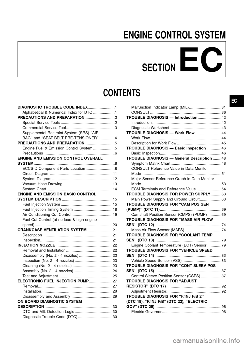
DIAGNOSTIC TROUBLE CODE INDEX .........................1
Alphabetical & Numerical Index for DTC ....................1
PRECAUTIONS AND PREPARATION ............................2
Special Service Tools ..................................................2
Commercial Service Tool .............................................3
Supplemental Restraint System (SRS) ``AIR
BAG'' and ``SEAT BELT PRE-TENSIONER''...............4
PRECAUTIONS AND PREPARATION ............................5
Engine Fuel & Emission Control System ....................5
Precautions ..................................................................6
ENGINE AND EMISSION CONTROL OVERALL
SYSTEM ........................................................................\
...8
ECCS-D Component Parts Location ...........................8
Circuit Diagram .......................................................... 11
System Diagram ........................................................12
Vacuum Hose Drawing ..............................................13
System Chart .............................................................14
ENGINE AND EMISSION BASIC CONTROL
SYSTEM DESCRIPTION ...............................................15
Fuel Injection System ................................................15
Fuel Injection Timing System ....................................18
Air Conditioning Cut Control ......................................19
Fuel Cut Control (at no load & high engine
speed) ........................................................................\
20
CRANKCASE VENTILATION SYSTEM ........................21
Description .................................................................21
Inspection...................................................................21
INJECTION NOZZLE .....................................................22
Removal and Installation ...........................................22
Disassembly (No. 2 - 4 nozzles) ...............................22
Inspection (No. 2 - 4 nozzles) ...................................23
Cleaning (No. 2 - 4 nozzles) .....................................23
Assembly (No. 2 - 4 nozzles) ....................................24
Test and Adjustment ..................................................25
ELECTRONIC FUEL INJECTION PUMP ......................27
Removal .....................................................................27
Installation ..................................................................28
Disassembly and Assembly .......................................29
ON BOARD DIAGNOSTIC SYSTEM
DESCRIPTION ...............................................................30
DTC and MIL Detection Logic ...................................30
Diagnostic Trouble Code (DTC) ................................30 Malfunction Indicator Lamp (MIL) ..............................31
CONSULT ..................................................................36
TROUBLE DIAGNOSIS Ð Introduction ......................42
Introduction ................................................................42
Diagnostic Worksheet ................................................43
TROUBLE DIAGNOSIS Ð Work Flow ........................44
Work Flow ..................................................................44
Description for Work Flow .........................................45
TROUBLE DIAGNOSIS Ð Basic Inspection ..............46
Basic Inspection.........................................................46
TROUBLE DIAGNOSIS Ð General Description ........48
Symptom Matrix Chart ...............................................48
CONSULT Reference Value in Data Monitor
Mode ........................................................................\
..51
Major Sensor Reference Graph in Data Monitor
Mode ........................................................................\
..53
ECM Terminals and Reference Value .......................54
TROUBLEDIAGNOSISFORPOWERSUPPLY ..........63
MainPowerSupplyandGroundCircuit....................63
TROUBLE DIAGNOSIS FOR ``CAM POS SEN
(PUMP)''(DTC11) .........................................................69
CamshaftPositionSensor(CMPS)(PUMP).............69
TROUBLEDIAGNOSISFOR``MASSAIRFLOW
SEN''(DTC12) ..............................................................74
MassAirFlowSensor(MAFS)..................................74
TROUBLEDIAGNOSISFOR``COOLANTTEMP
SEN''(DTC13) ..............................................................79
EngineCoolantTemperature(ECT)Sensor.............79
TROUBLEDIAGNOSISFOR``VEHICLESPEED
SEN''(DTC14) ..............................................................83
VehicleSpeedSensor(VSS)....................................83
TROUBLEDIAGNOSISFOR``CONTSLEEVPOS
SEN''(DTC15) ..............................................................87
ControlSleevePositionSensor(CSPS)...................87
TROUBLEDIAGNOSISFOR``ADJUST
RESISTOR''(DTC17) ...................................................92
AdjustmentResistor...................................................92
TROUBLEDIAGNOSISFOR``F/INJF/B2''
(DTC18),``F/INJF/B''(DTC22),``ELECTRIC
GOV''(DTC25) ..............................................................96
ElectricGovernor.......................................................96
EC
Page 2 of 192
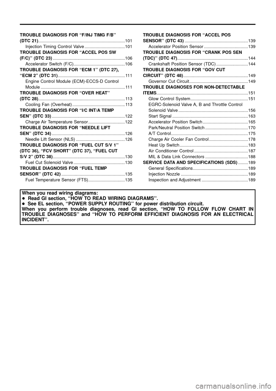
TROUBLEDIAGNOSISFOR``F/INJTIMGF/B''
(DTC21).......................................................................101
InjectionTimingControlValve.................................101
TROUBLEDIAGNOSISFOR``ACCELPOSSW
(F/C)''(DTC23) ...........................................................106
AcceleratorSwitch(F/C)..........................................106
TROUBLEDIAGNOSISFOR``ECM1''(DTC27),
``ECM2''(DTC31) .......................................................111
EngineControlModule(ECM)-ECCS-DControl
Module.....................................................................111
TROUBLEDIAGNOSISFOR``OVERHEAT''
(DTC28) .......................................................................113
CoolingFan(Overheat)...........................................113
TROUBLEDIAGNOSISFOR``I/CINT/ATEMP
SEN''(DTC33) ............................................................122
ChargeAirTemperatureSensor..............................122
TROUBLEDIAGNOSISFOR``NEEDLELIFT
SEN''(DTC34) ............................................................126
NeedleLiftSensor(NLS)........................................126
TROUBLE DIAGNOSIS FOR ``FUEL CUT S/V 1''
(DTC 36), ``FCV SHORT'' (DTC 37), ``FUEL CUT
S/V2''(DTC38) ...........................................................130
FuelCutSolenoidValve..........................................130
TROUBLE DIAGNOSIS FOR ``FUEL TEMP
SENSOR''(DTC42) ....................................................135
FuelTemperatureSensor(FTS)..............................135 TROUBLE DIAGNOSIS FOR ``ACCEL POS
SENSOR''(DTC43)
....................................................139
AcceleratorPositionSensor....................................139
TROUBLE DIAGNOSIS FOR ``CRANK POS SEN
(TDC)''(DTC47) ..........................................................144
CrankshaftPositionSensor(TDC)..........................144
TROUBLEDIAGNOSISFOR``GOVCUT
CIRCUIT''(DTC48) .....................................................149
GovernorCutCircuit................................................149
TROUBLEDIAGNOSESFORNON-DETECTABLE
ITEMS ........................................................................\
...151
GlowControlSystem...............................................151
EGRC-SolenoidValveA,BandThrottleControl
SolenoidValve.........................................................156
StartSignal..............................................................163
AcceleratorPositionSwitch.....................................165
Park/NeutralPositionSwitch...................................170
A/TControl...............................................................175
ChargeAirCoolerFanControl................................178
HeatUpSwitch........................................................183
AirConditionerControl............................................187
MIL&DataLinkConnectors...................................188
SERVICEDATAANDSPECIFICATIONS(SDS) ........189
GeneralSpeci®cations.............................................189
InjectionNozzle.......................................................189
InspectionandAdjustment......................................189
When you read wiring diagrams:
+ Read GI section, ``HOW TO READ WIRING DIAGRAMS''.
+ See EL section, ``POWER SUPPLY ROUTING'' for power distribution circuit.
When you perform trouble diagnoses, read GI section, ``HOW TO FOLLOW FLOW CHART IN
TROUBLE DIAGNOSES'' and ``HOW TO PERFORM EFFICIENT DIAGNOSIS FOR AN ELECTRICAL
INCIDENT''.
Page 3 of 192
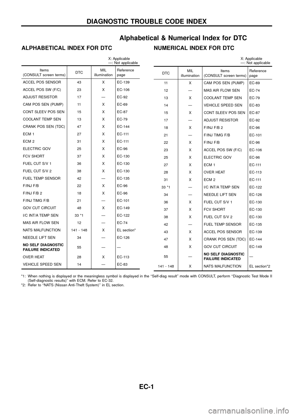
Alphabetical & Numerical Index for DTC
ALPHABETICAL INDEX FOR DTC
X: Applicable
Ð: Not applicable
Items
(CONSULT screen terms) DTCMIL
illumination Reference
page
ACCEL POS SENSOR 43 X EC-139
ACCEL POS SW (F/C) 23 X EC-106
ADJUST RESISTOR 17 Ð EC-92
CAM POS SEN (PUMP) 11 X EC-69
CONT SLEEV POS SEN 15 X EC-87
COOLANT TEMP SEN 13 X EC-79
CRANK POS SEN (TDC) 47 X EC-144
ECM 1 27 X EC-111
ECM 2 31 X EC-111
ELECTRIC GOV 25 X EC-96
FCV SHORT 37 X EC-130
FUEL CUT S/V 1 36 X EC-130
FUEL CUT S/V 2 38 X EC-130
FUEL TEMP SENSOR 42 Ð EC-135
F/INJ F/B 22 X EC-96
F/INJ F/B 2 18 X EC-96
F/INJ TIMG F/B 21 Ð EC-101
GOV CUT CIRCUIT 48 X EC-149
I/C INT/A TEMP SEN 33 *1 Ð EC-122
MAS AIR FLOW SEN 12 Ð EC-74
NATS MALFUNCTION 141 - 148 X EL section*
NEEDLE LIFT SEN 34 Ð EC-126
NO SELF DIAGNOSTIC
FAILURE INDICATED 55 Ð Ð
OVER HEAT 28 X EC-113
VEHICLE SPEED SEN 14 Ð EC-83
NUMERICAL INDEX FOR DTC
X: Applicable
Ð: Not applicable
DTC MIL
illumination Items
(CONSULT screen terms) Reference
page
11 X CAM POS SEN (PUMP) EC-69
12 Ð MAS AIR FLOW SEN EC-74
13 X COOLANT TEMP SEN EC-79
14 Ð VEHICLE SPEED SEN EC-83
15 X CONT SLEEV POS SEN EC-87
17 Ð ADJUST RESISTOR EC-92
18 X F/INJ F/B 2 EC-96
21 Ð F/INJ TIMG F/B EC-101
22 X F/INJ F/B EC-96
23 X ACCEL POS SW (F/C) EC-106
25 X ELECTRIC GOV EC-96
27 X ECM 1 EC-111
28 X OVER HEAT EC-113
31 X ECM 2 EC-111
33 *1 Ð I/C INT/A TEMP SEN EC-122 34 Ð NEEDLE LIFT SEN EC-126
36 X FUEL CUT S/V 1 EC-130
37 X FCV SHORT EC-130
38 X FUEL CUT S/V 2 EC-130
42 Ð FUEL TEMP SENSOR EC-135
43 X ACCEL POS SENSOR EC-139
47 X CRANK POS SEN (TDC) EC-144
48 X GOV CUT CIRCUIT EC-149
55 Ð NO SELF DIAGNOSTIC
FAILURE INDICATED Ð
141 - 148 X NATS MALFUNCTION EL section*2
*1: When nothing is displayed or the meaningless symbol is displayed in the ``Self-diag result'' mode with CONSULT, perform ``Diagnostic Test Mode II (Self-diagnostic results)'' with ECM. Refer to EC-32.
*2: Refer to ``NATS (Nissan Anti-Theft System)'' in EL section.
DIAGNOSTIC TROUBLE CODE INDEX
EC-1
Page 8 of 192
Precautions
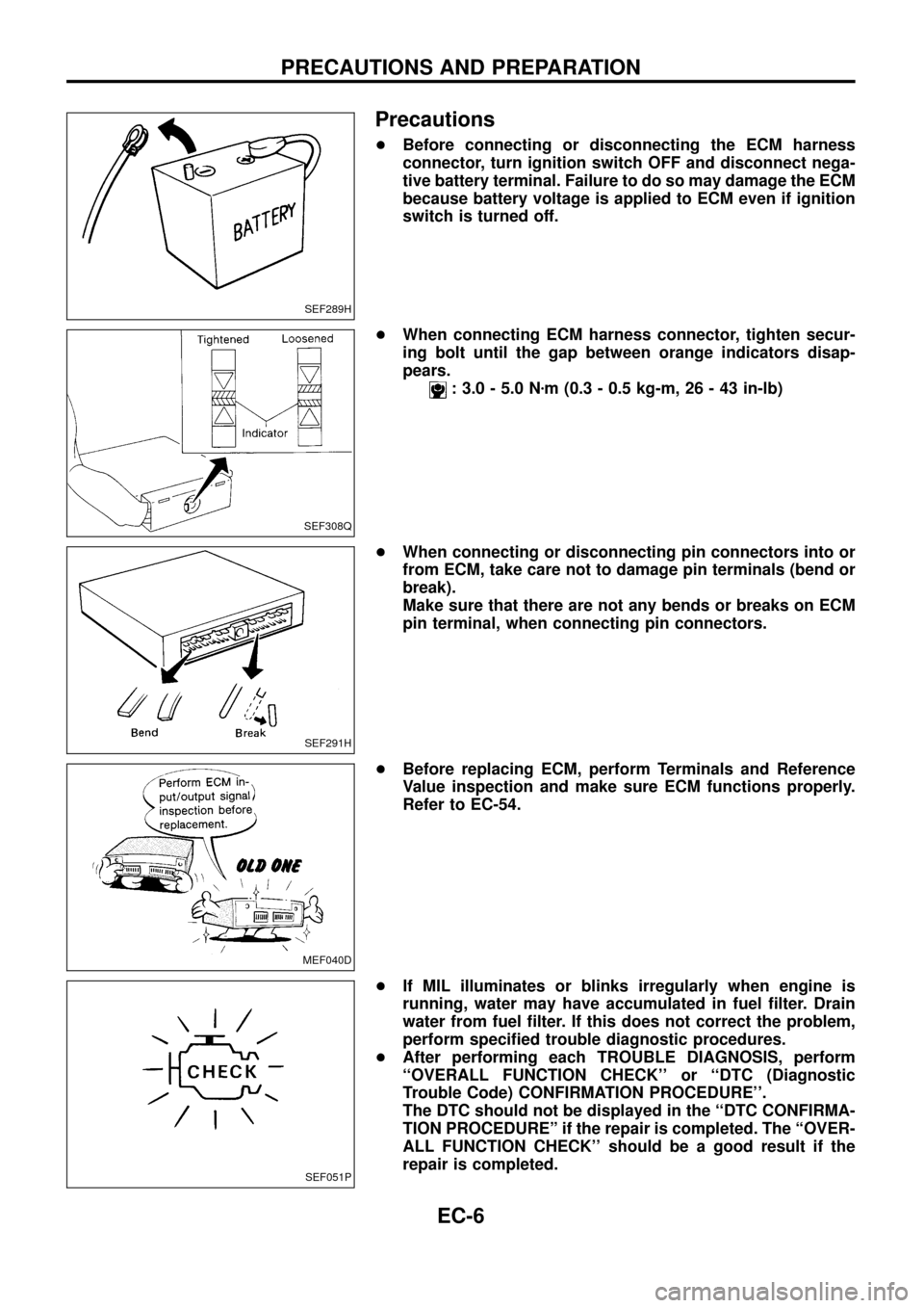
+Before connecting or disconnecting the ECM harness
connector, turn ignition switch OFF and disconnect nega-
tive battery terminal. Failure to do so may damage the ECM
because battery voltage is applied to ECM even if ignition
switch is turned off.
+When connecting ECM harness connector, tighten secur-
ing bolt until the gap between orange indicators disap-
pears.
: 3.0 - 5.0 Nzm (0.3 - 0.5 kg-m, 26 - 43 in-lb)
+When connecting or disconnecting pin connectors into or
from ECM, take care not to damage pin terminals (bend or
break).
Make sure that there are not any bends or breaks on ECM
pin terminal, when connecting pin connectors.
+Before replacing ECM, perform Terminals and Reference
Value inspection and make sure ECM functions properly.
Refer to EC-54.
+If MIL illuminates or blinks irregularly when engine is
running, water may have accumulated in fuel ®lter. Drain
water from fuel ®lter. If this does not correct the problem,
perform speci®ed trouble diagnostic procedures.
+After performing each TROUBLE DIAGNOSIS, perform
``OVERALL FUNCTION CHECK'' or ``DTC (Diagnostic
Trouble Code) CONFIRMATION PROCEDURE''.
The DTC should not be displayed in the ``DTC CONFIRMA-
TION PROCEDUREº if the repair is completed. The ``OVER-
ALL FUNCTION CHECK'' should be a good result if the
repair is completed.
SEF289H
SEF308Q
SEF291H
MEF040D
SEF051P
PRECAUTIONS AND PREPARATION
EC-6
Page 22 of 192
Fuel Cut Control (at no load & high engine
speed)
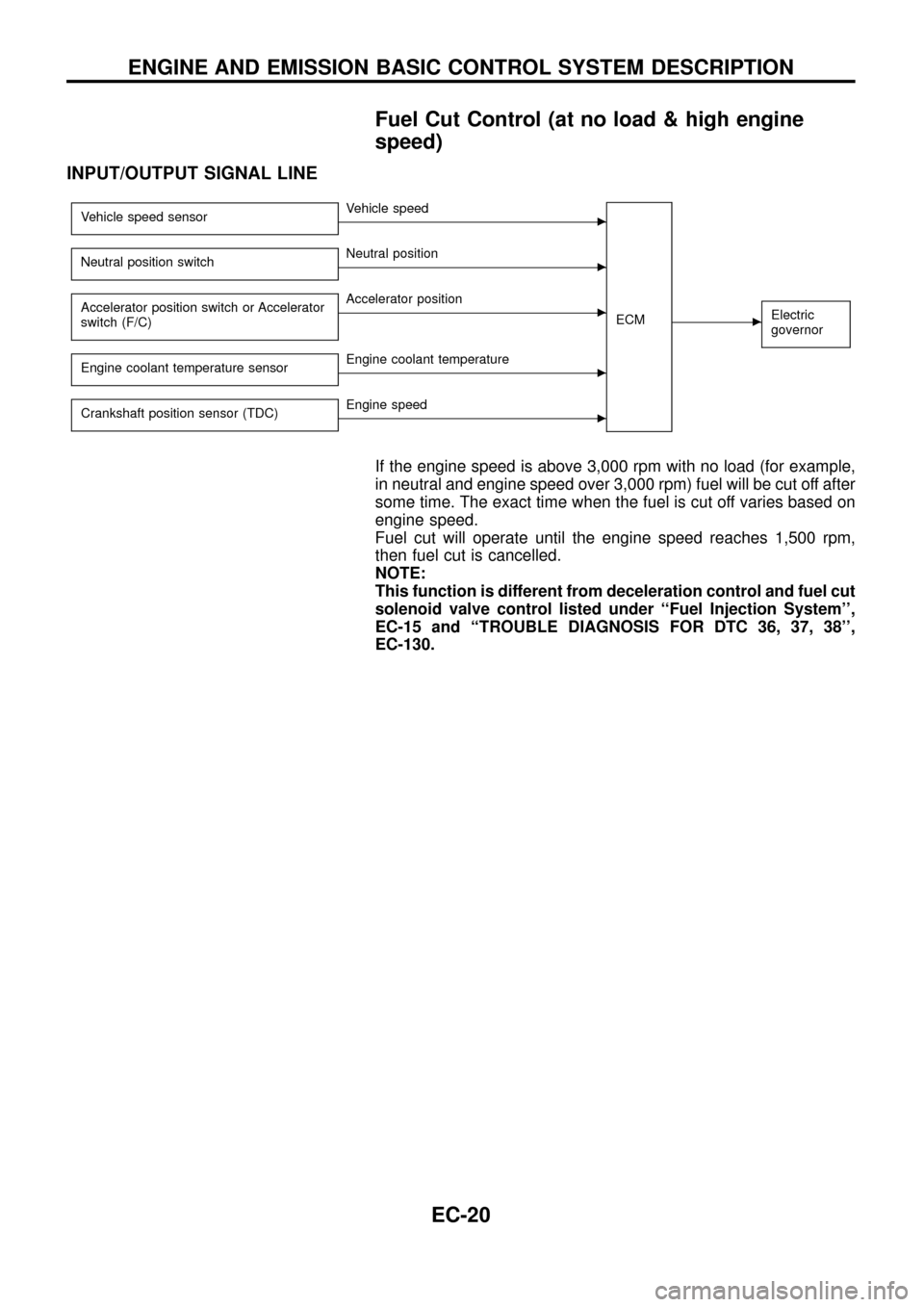
INPUT/OUTPUT SIGNAL LINE
Vehicle speed sensorcVehicle speed
ECM
cElectric
governor
Neutral position switchcNeutral position
Accelerator position switch or Accelerator
switch (F/C)
cAccelerator position
Engine coolant temperature sensor
cEngine coolant temperature
Crankshaft position sensor (TDC)
cEngine speed
If the engine speed is above 3,000 rpm with no load (for example,
in neutral and engine speed over 3,000 rpm) fuel will be cut off after
some time. The exact time when the fuel is cut off varies based on
engine speed.
Fuel cut will operate until the engine speed reaches 1,500 rpm,
then fuel cut is cancelled.
NOTE:
This function is different from deceleration control and fuel cut
solenoid valve control listed under ``Fuel Injection System'',
EC-15 and ``TROUBLE DIAGNOSIS FOR DTC 36, 37, 38'',
EC-130.
ENGINE AND EMISSION BASIC CONTROL SYSTEM DESCRIPTION
EC-20
Page 31 of 192
Disassembly and Assembly
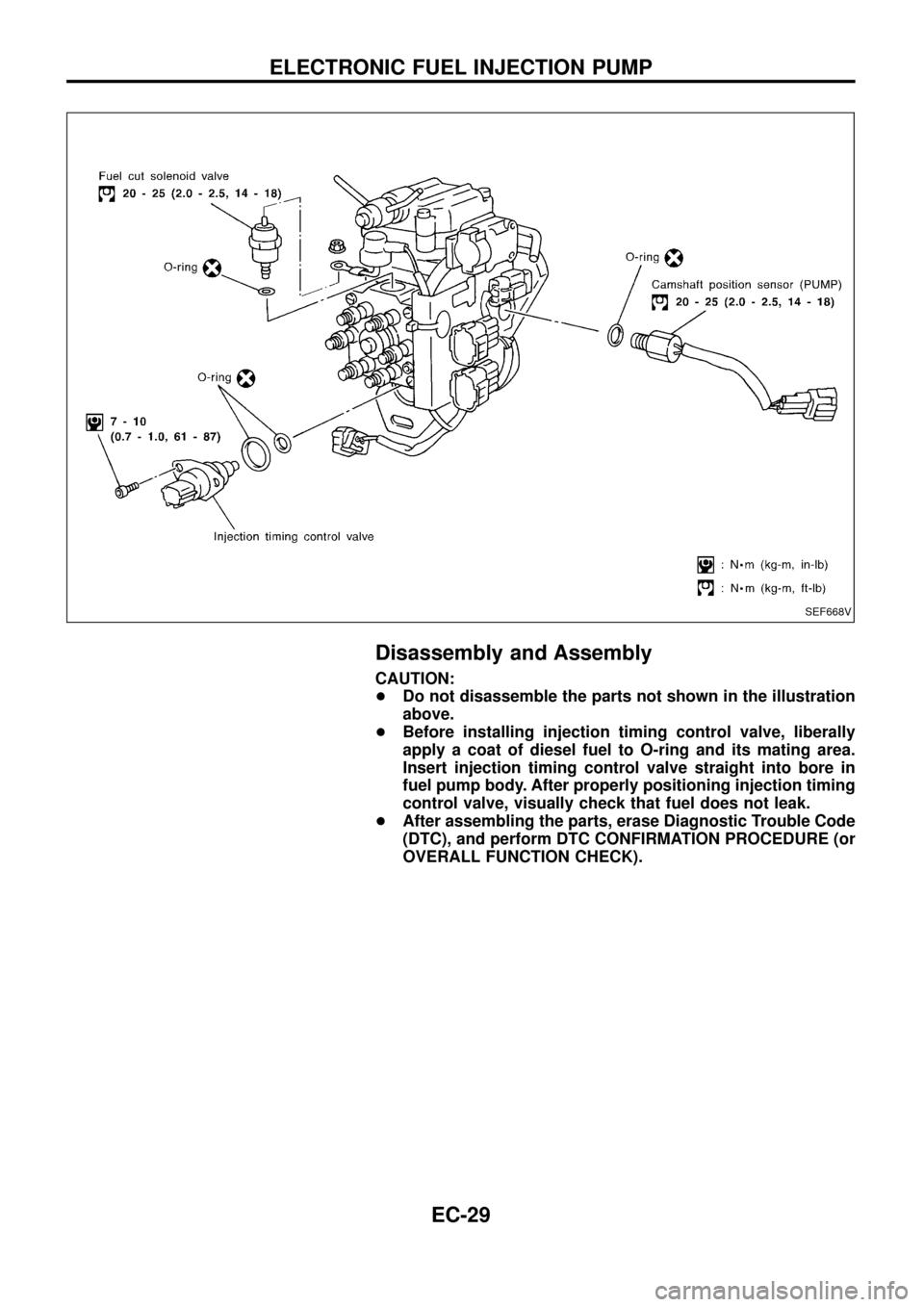
CAUTION:
+Do not disassemble the parts not shown in the illustration
above.
+Before installing injection timing control valve, liberally
apply a coat of diesel fuel to O-ring and its mating area.
Insert injection timing control valve straight into bore in
fuel pump body. After properly positioning injection timing
control valve, visually check that fuel does not leak.
+After assembling the parts, erase Diagnostic Trouble Code
(DTC), and perform DTC CONFIRMATION PROCEDURE (or
OVERALL FUNCTION CHECK).
SEF668V
ELECTRONIC FUEL INJECTION PUMP
EC-29
Page 32 of 192
DTC and MIL Detection Logic
When a malfunction is detected for the ®rst time, the malfunction (DTC) is stored in the ECM memory.
The MIL will light up each time the ECM detects malfunction. However, if the same malfunction is experienced
in two consecutive driving patterns and the engine is still running, the MIL will stay lit up. For diagnostic items
causing the MIL to light up, refer to ``DIAGNOSTIC TROUBLE CODE INDEX'', EC-1.
Diagnostic Trouble Code (DTC)
HOW TO READ DTC
The diagnostic trouble code can be read by the following methods.
1. The number of blinks of the malfunction indicator lamp in the Diagnostic Test Mode II (Self-Diagnostic
Results) Examples: 11, 13, 14, etc.
These DTCs are controlled by NISSAN.
2. CONSULT Examples: ``CAM POS SEN (PUMP)'', etc.
+Output of the trouble code means that the indicated circuit has a malfunction. However, in the Mode
II it does not indicate whether the malfunction is still occurring or occurred in the past and returned
to normal.
CONSULT can identify them. Therefore, using CONSULT (if available) is recommended.
HOW TO ERASE DTC
The diagnostic trouble code can be erased by the following methods.
Selecting ``ERASE'' in the ``SELF-DIAG RESULTS'' mode with CONSULT.
Changing the diagnostic test mode from Diagnostic Test Mode II to Mode I. (Refer to EC-32.)
+If the battery terminal is disconnected, the diagnostic trouble code will be lost within 24 hours.
+When you erase the DTC, using CONSULT is easier and quicker than switching the diagnostic test
modes.
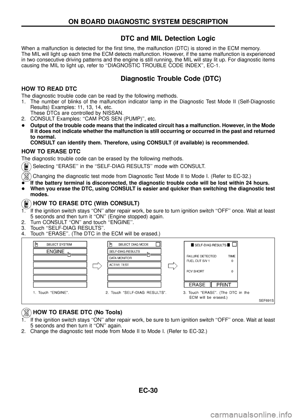
HOW TO ERASE DTC (With CONSULT)
1. If the ignition switch stays ``ON'' after repair work, be sure to turn ignition switch ``OFF'' once. Wait at least
5 seconds and then turn it ``ON'' (Engine stopped) again.
2. Turn CONSULT ``ON'' and touch ``ENGINE''.
3. Touch ``SELF-DIAG RESULTS''.
4. Touch ``ERASE''. (The DTC in the ECM will be erased.)
HOW TO ERASE DTC (No Tools)
1. If the ignition switch stays ``ON'' after repair work, be sure to turn ignition switch ``OFF'' once. Wait at least
5 seconds and then turn it ``ON'' again.
2. Change the diagnostic test mode from Mode II to Mode I. (Refer to EC-32.)
SEF691S
ON BOARD DIAGNOSTIC SYSTEM DESCRIPTION
EC-30
Page 36 of 192
DIAGNOSTIC TEST MODE IÐBULB CHECK
In this mode, the MALFUNCTION INDICATOR LAMP on the instrument panel should stay ON. If it remains
OFF, check the bulb. Refer to EL section (``WARNING LAMPS AND CHIME'') or see EC-188.
DIAGNOSTIC TEST MODE IÐMALFUNCTION WARNING
MALFUNCTION
INDICATOR LAMPCondition
ONWhen the malfunction is detected or the ECM's CPU is malfunctioning. (Refer to ``MIL Illumination'' of the
``DIAGNOSTIC TROUBLE CODE INDEX'', EC-1.)
OFF No malfunction.
+These Diagnostic Trouble Code Numbers are clari®ed in Diagnostic Test Mode II (SELF-DIAGNOSTIC
RESULTS).
DIAGNOSTIC TEST MODE IIÐSELF-DIAGNOSTIC RESULTS
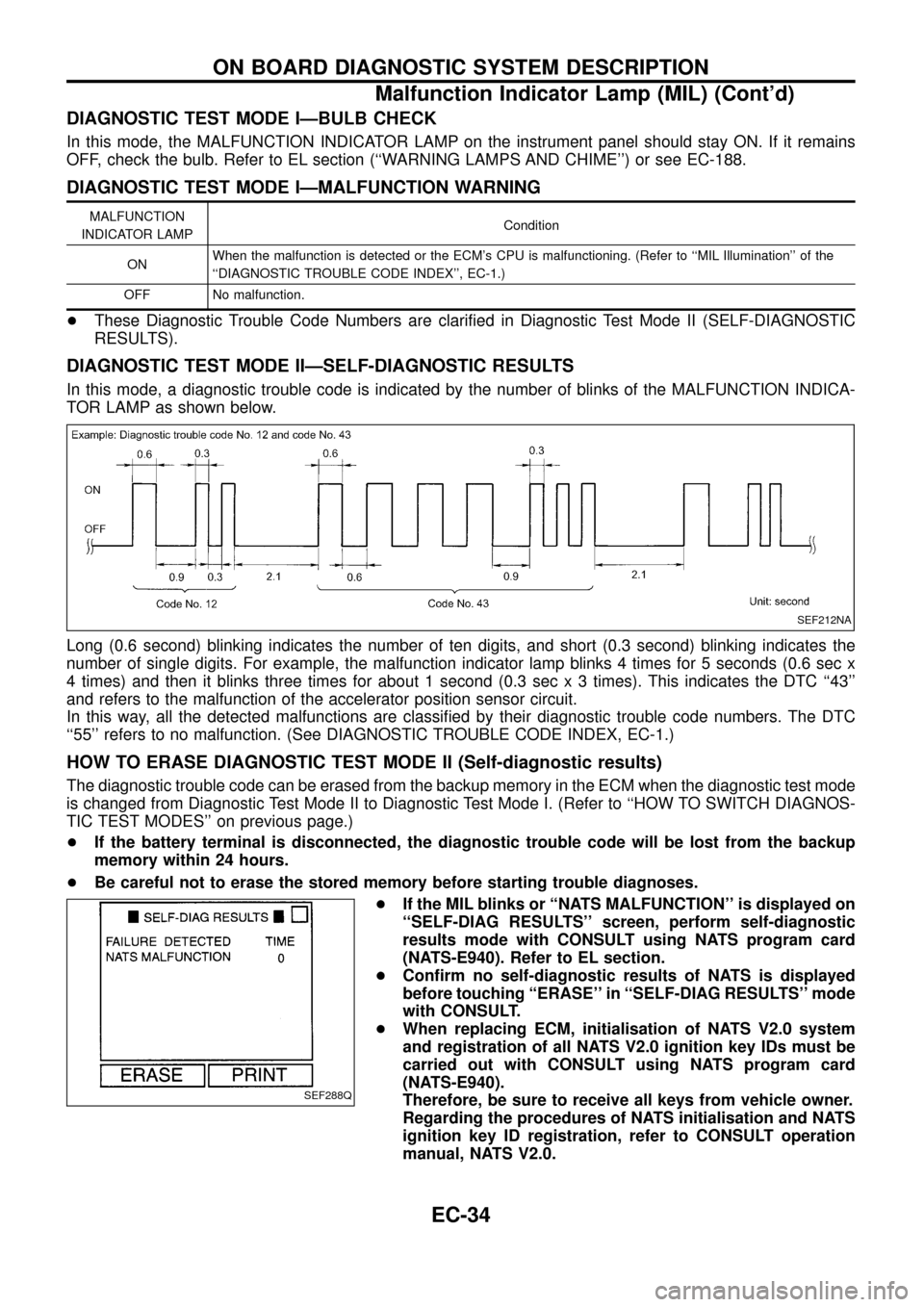
In this mode, a diagnostic trouble code is indicated by the number of blinks of the MALFUNCTION INDICA-
TOR LAMP as shown below.
Long (0.6 second) blinking indicates the number of ten digits, and short (0.3 second) blinking indicates the
number of single digits. For example, the malfunction indicator lamp blinks 4 times for 5 seconds (0.6 sec x
4 times) and then it blinks three times for about 1 second (0.3 sec x 3 times). This indicates the DTC ``43''
and refers to the malfunction of the accelerator position sensor circuit.
In this way, all the detected malfunctions are classi®ed by their diagnostic trouble code numbers. The DTC
``55'' refers to no malfunction. (See DIAGNOSTIC TROUBLE CODE INDEX, EC-1.)
HOW TO ERASE DIAGNOSTIC TEST MODE II (Self-diagnostic results)
The diagnostic trouble code can be erased from the backup memory in the ECM when the diagnostic test mode
is changed from Diagnostic Test Mode II to Diagnostic Test Mode I. (Refer to ``HOW TO SWITCH DIAGNOS-
TIC TEST MODES'' on previous page.)
+If the battery terminal is disconnected, the diagnostic trouble code will be lost from the backup
memory within 24 hours.
+Be careful not to erase the stored memory before starting trouble diagnoses.
+If the MIL blinks or ``NATS MALFUNCTION'' is displayed on
``SELF-DIAG RESULTS'' screen, perform self-diagnostic
results mode with CONSULT using NATS program card
(NATS-E940). Refer to EL section.
+Con®rm no self-diagnostic results of NATS is displayed
before touching ``ERASE'' in ``SELF-DIAG RESULTS'' mode
with CONSULT.
+When replacing ECM, initialisation of NATS V2.0 system
and registration of all NATS V2.0 ignition key IDs must be
carried out with CONSULT using NATS program card
(NATS-E940).
Therefore, be sure to receive all keys from vehicle owner.
Regarding the procedures of NATS initialisation and NATS
ignition key ID registration, refer to CONSULT operation
manual, NATS V2.0.
SEF212NA
SEF288Q
ON BOARD DIAGNOSTIC SYSTEM DESCRIPTION
Malfunction Indicator Lamp (MIL) (Cont'd)
EC-34