Page 57 of 192
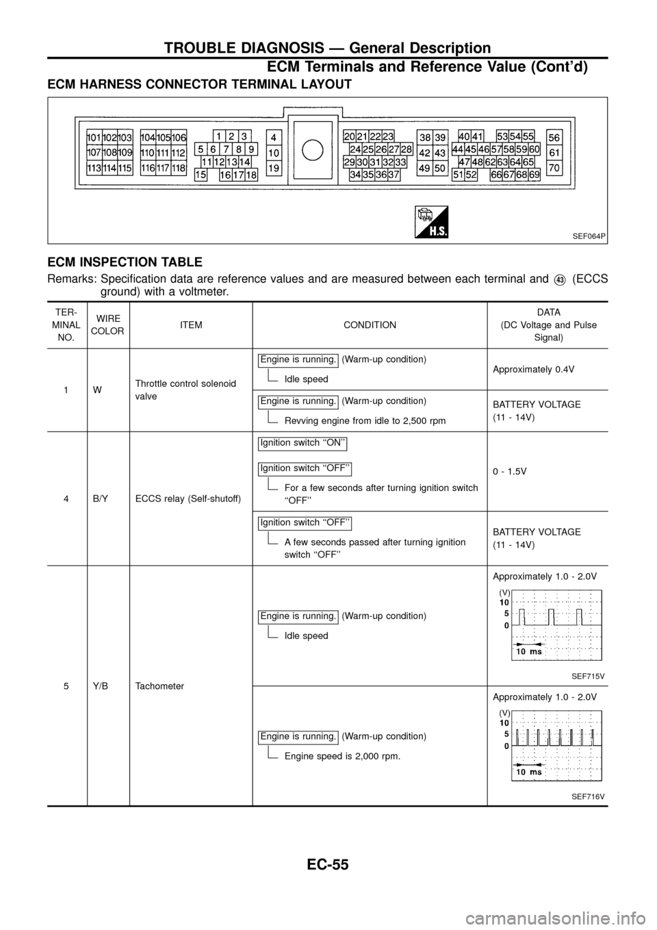
ECM HARNESS CONNECTOR TERMINAL LAYOUT
ECM INSPECTION TABLE
Remarks: Speci®cation data are reference values and are measured between each terminal andV43(ECCS
ground) with a voltmeter.
TER-
MINAL
NO.WIRE
COLORITEM CONDITIONDATA
(DC Voltage and Pulse
Signal)
1WThrottle control solenoid
valveEngine is running.
(Warm-up condition)
Idle speedApproximately 0.4V
Engine is running.
(Warm-up condition)
Revving engine from idle to 2,500 rpmBATTERY VOLTAGE
(11 - 14V)
4 B/Y ECCS relay (Self-shutoff)Ignition switch ``ON''
Ignition switch ``OFF''
For a few seconds after turning ignition switch
``OFF''0 - 1.5V
Ignition switch ``OFF''
A few seconds passed after turning ignition
switch ``OFF''BATTERY VOLTAGE
(11 - 14V)
5 Y/B TachometerEngine is running.
(Warm-up condition)
Idle speedApproximately 1.0 - 2.0V
SEF715V
Engine is running.(Warm-up condition)
Engine speed is 2,000 rpm.Approximately 1.0 - 2.0V
SEF716V
SEF064P
TROUBLE DIAGNOSIS Ð General Description
ECM Terminals and Reference Value (Cont'd)
EC-55
Page 58 of 192
TER-
MINAL
NO.WIRE
COLORITEM CONDITIONDATA
(DC Voltage and Pulse
Signal)
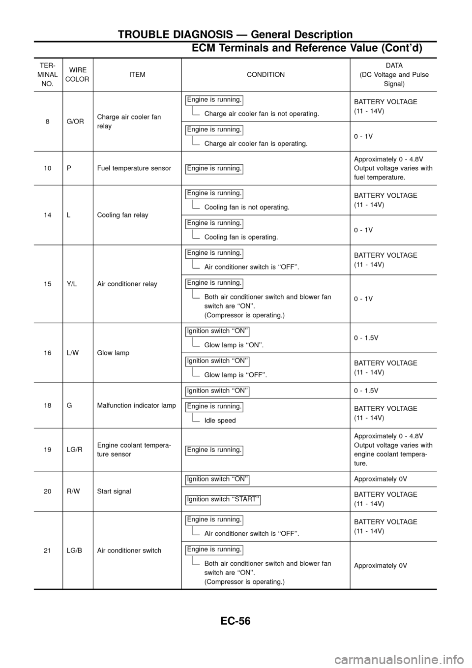
8 G/ORCharge air cooler fan
relayEngine is running.
Charge air cooler fan is not operating.BATTERY VOLTAGE
(11 - 14V)
Engine is running.
Charge air cooler fan is operating.0-1V
10 P Fuel temperature sensor Engine is running.
Approximately 0 - 4.8V
Output voltage varies with
fuel temperature.
14 L Cooling fan relayEngine is running.
Cooling fan is not operating.BATTERY VOLTAGE
(11 - 14V)
Engine is running.
Cooling fan is operating.0-1V
15 Y/L Air conditioner relayEngine is running.
Air conditioner switch is ``OFF''.BATTERY VOLTAGE
(11 - 14V)
Engine is running.
Both air conditioner switch and blower fan
switch are ``ON''.
(Compressor is operating.)0-1V
16 L/W Glow lampIgnition switch ``ON''
Glow lamp is ``ON''.0 - 1.5V
Ignition switch ``ON''
Glow lamp is ``OFF''.BATTERY VOLTAGE
(11 - 14V)
18 G Malfunction indicator lampIgnition switch ``ON''
0 - 1.5V
Engine is running.
Idle speedBATTERY VOLTAGE
(11 - 14V)
19 LG/REngine coolant tempera-
ture sensorEngine is running.
Approximately 0 - 4.8V
Output voltage varies with
engine coolant tempera-
ture.
20 R/W Start signalIgnition switch ``ON''
Approximately 0V
Ignition switch ``START''
BATTERY VOLTAGE
(11 - 14V)
21 LG/B Air conditioner switchEngine is running.
Air conditioner switch is ``OFF''.BATTERY VOLTAGE
(11 - 14V)
Engine is running.
Both air conditioner switch and blower fan
switch are ``ON''.
(Compressor is operating.)Approximately 0V
TROUBLE DIAGNOSIS Ð General Description
ECM Terminals and Reference Value (Cont'd)
EC-56
Page 59 of 192
TER-
MINAL
NO.WIRE
COLORITEM CONDITIONDATA
(DC Voltage and Pulse
Signal)
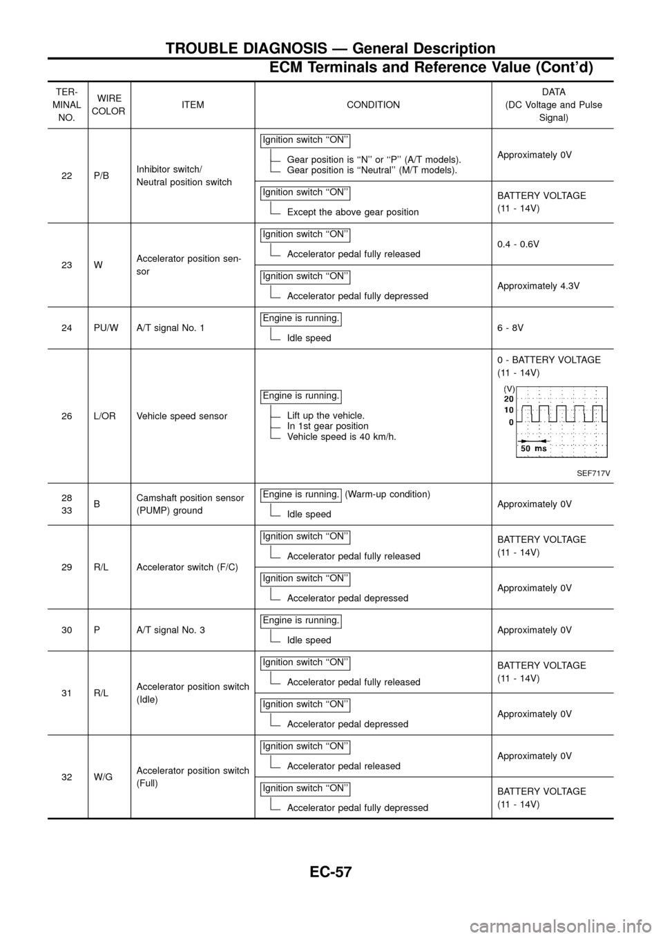
22 P/BInhibitor switch/
Neutral position switchIgnition switch ``ON''
Gear position is ``N'' or ``P'' (A/T models).Gear position is ``Neutral'' (M/T models).Approximately 0V
Ignition switch ``ON''
Except the above gear positionBATTERY VOLTAGE
(11 - 14V)
23 WAccelerator position sen-
sorIgnition switch ``ON''
Accelerator pedal fully released0.4 - 0.6V
Ignition switch ``ON''
Accelerator pedal fully depressedApproximately 4.3V
24 PU/W A/T signal No. 1Engine is running.
Idle speed6-8V
26 L/OR Vehicle speed sensorEngine is running.
Lift up the vehicle.In 1st gear positionVehicle speed is 40 km/h.0 - BATTERY VOLTAGE
(11 - 14V)
SEF717V
28
33BCamshaft position sensor
(PUMP) groundEngine is running.(Warm-up condition)
Idle speedApproximately 0V
29 R/L Accelerator switch (F/C)Ignition switch ``ON''
Accelerator pedal fully releasedBATTERY VOLTAGE
(11 - 14V)
Ignition switch ``ON''
Accelerator pedal depressedApproximately 0V
30 P A/T signal No. 3Engine is running.
Idle speedApproximately 0V
31 R/LAccelerator position switch
(Idle)Ignition switch ``ON''
Accelerator pedal fully releasedBATTERY VOLTAGE
(11 - 14V)
Ignition switch ``ON''
Accelerator pedal depressedApproximately 0V
32 W/GAccelerator position switch
(Full)Ignition switch ``ON''
Accelerator pedal releasedApproximately 0V
Ignition switch ``ON''
Accelerator pedal fully depressedBATTERY VOLTAGE
(11 - 14V)
TROUBLE DIAGNOSIS Ð General Description
ECM Terminals and Reference Value (Cont'd)
EC-57
Page 60 of 192
TER-
MINAL
NO.WIRE
COLORITEM CONDITIONDATA
(DC Voltage and Pulse
Signal)
34 W Needle lift sensorEngine is running.
(Warm-up condition)
Idle speedApproximately 0V
SEF718V
Engine is running.(Warm-up condition)
Engine speed is 2,000 rpm.Approximately 0V
SEF719V
35 R Mass air ¯ow sensorEngine is running.(Warm-up condition)
Idle speed1.6 - 2.0V
36 LGCharge air temperature
sensorEngine is running.
Approximately 0 - 4.8V
Output voltage varies with
charge air temperature.
37 P/B A/T signal No. 2Engine is running.
Idle speed6-8V
38 B/Y Ignition switchIgnition switch ``OFF''
0V
Ignition switch ``ON''
BATTERY VOLTAGE
(11 - 14V)
39
43B ECCS groundEngine is running.
Idle speedEngine ground
(Probe this terminal with
@tester probe when
measuring.)
TROUBLE DIAGNOSIS Ð General Description
ECM Terminals and Reference Value (Cont'd)
EC-58
Page 61 of 192
TER-
MINAL
NO.WIRE
COLORITEM CONDITIONDATA
(DC Voltage and Pulse
Signal)
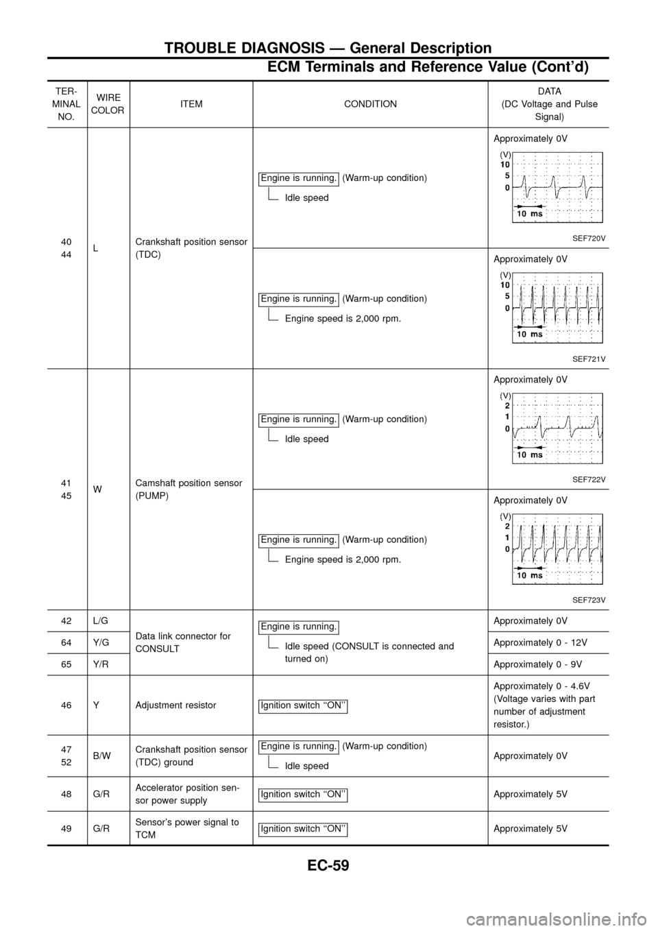
40
44LCrankshaft position sensor
(TDC)Engine is running.
(Warm-up condition)
Idle speedApproximately 0V
SEF720V
Engine is running.(Warm-up condition)
Engine speed is 2,000 rpm.Approximately 0V
SEF721V
41
45WCamshaft position sensor
(PUMP)Engine is running.
(Warm-up condition)
Idle speedApproximately 0V
SEF722V
Engine is running.(Warm-up condition)
Engine speed is 2,000 rpm.Approximately 0V
SEF723V
42 L/G
Data link connector for
CONSULTEngine is running.
Idle speed (CONSULT is connected and
turned on)Approximately 0V
64 Y/GApproximately0-12V
65 Y/RApproximately0-9V
46 Y Adjustment resistor Ignition switch ``ON''
Approximately 0 - 4.6V
(Voltage varies with part
number of adjustment
resistor.)
47
52B/WCrankshaft position sensor
(TDC) groundEngine is running.
(Warm-up condition)
Idle speedApproximately 0V
48 G/RAccelerator position sen-
sor power supplyIgnition switch ``ON''
Approximately 5V
49 G/RSensor's power signal to
TCMIgnition switch ``ON''
Approximately 5V
TROUBLE DIAGNOSIS Ð General Description
ECM Terminals and Reference Value (Cont'd)
EC-59
Page 62 of 192
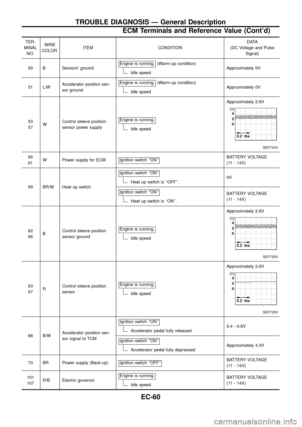
TER-
MINAL
NO.WIRE
COLORITEM CONDITIONDATA
(DC Voltage and Pulse
Signal)
50 B Sensors' groundEngine is running.
(Warm-up condition)
Idle speedApproximately 0V
51 L/WAccelerator position sen-
sor groundEngine is running.
(Warm-up condition)
Idle speedApproximately 0V
53
57WControl sleeve position
sensor power supplyEngine is running.
Idle speedApproximately 2.6V
SEF724V
56
61W Power supply for ECM Ignition switch ``ON''BATTERY VOLTAGE
(11 - 14V)
59 BR/W Heat up switchIgnition switch ``ON''
Heat up switch is ``OFF''.0V
Ignition switch ``ON''
Heat up switch is ``ON''.BATTERY VOLTAGE
(11 - 14V)
62
66BControl sleeve position
sensor groundEngine is running.
Idle speedApproximately 2.6V
SEF725V
63
67RControl sleeve position
sensorEngine is running.
Idle speedApproximately 2.6V
SEF726V
68 B/WAccelerator position sen-
sor signal to TCMIgnition switch ``ON''Accelerator pedal fully released0.4 - 0.6V
Ignition switch ``ON''
Accelerator pedal fully depressedApproximately 4.3V
70 BR Power supply (Back-up) Ignition switch ``OFF''
BATTERY VOLTAGE
(11 - 14V)
101
107R/B Electric governorEngine is running.
Idle speedBATTERY VOLTAGE
(11 - 14V)
TROUBLE DIAGNOSIS Ð General Description
ECM Terminals and Reference Value (Cont'd)
EC-60
Page 63 of 192
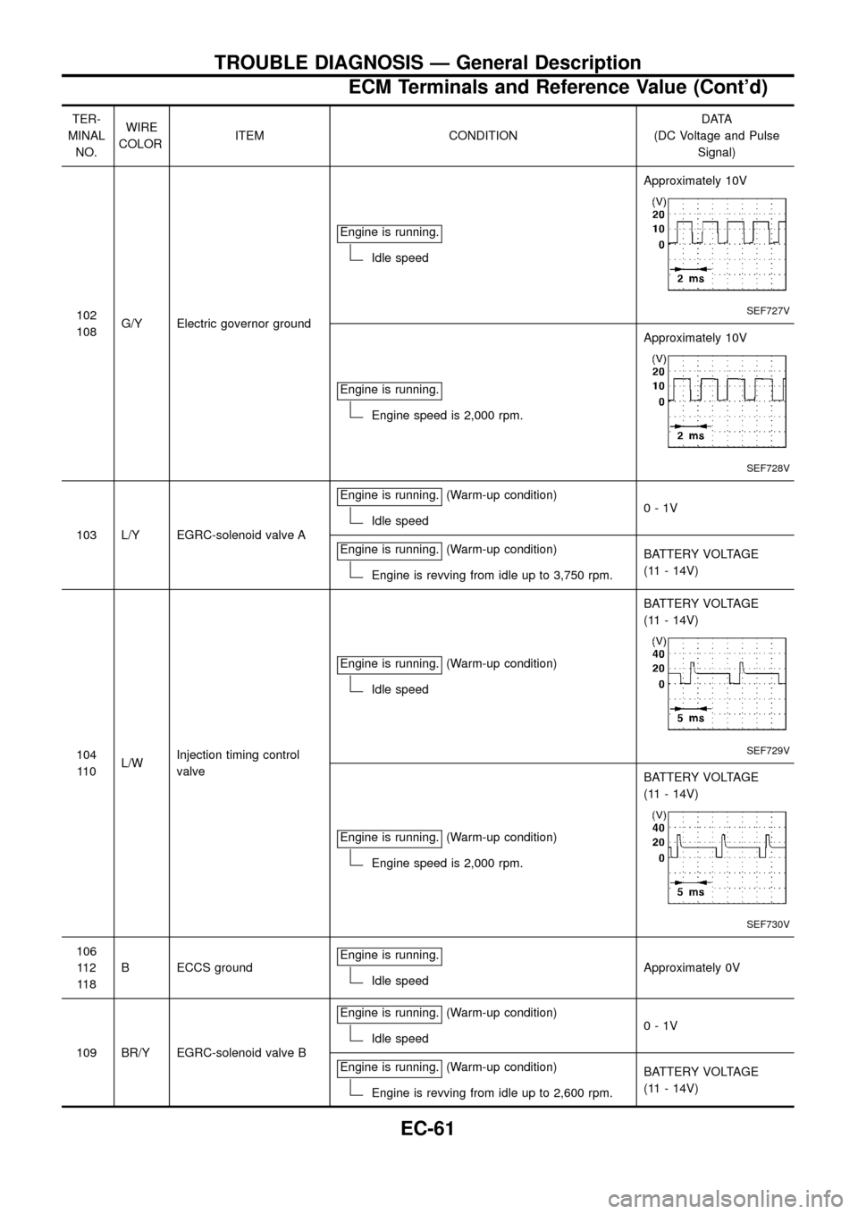
TER-
MINAL
NO.WIRE
COLORITEM CONDITIONDATA
(DC Voltage and Pulse
Signal)
102
108G/Y Electric governor groundEngine is running.
Idle speedApproximately 10V
SEF727V
Engine is running.
Engine speed is 2,000 rpm.Approximately 10V
SEF728V
103 L/Y EGRC-solenoid valve AEngine is running.
(Warm-up condition)
Idle speed0-1V
Engine is running.
(Warm-up condition)
Engine is revving from idle up to 3,750 rpm.BATTERY VOLTAGE
(11 - 14V)
104
11 0L/WInjection timing control
valveEngine is running.
(Warm-up condition)
Idle speedBATTERY VOLTAGE
(11 - 14V)
SEF729V
Engine is running.(Warm-up condition)
Engine speed is 2,000 rpm.BATTERY VOLTAGE
(11 - 14V)
SEF730V
106
11 2
11 8B ECCS groundEngine is running.
Idle speedApproximately 0V
109 BR/Y EGRC-solenoid valve BEngine is running.
(Warm-up condition)
Idle speed0-1V
Engine is running.
(Warm-up condition)
Engine is revving from idle up to 2,600 rpm.BATTERY VOLTAGE
(11 - 14V)
TROUBLE DIAGNOSIS Ð General Description
ECM Terminals and Reference Value (Cont'd)
EC-61
Page 65 of 192
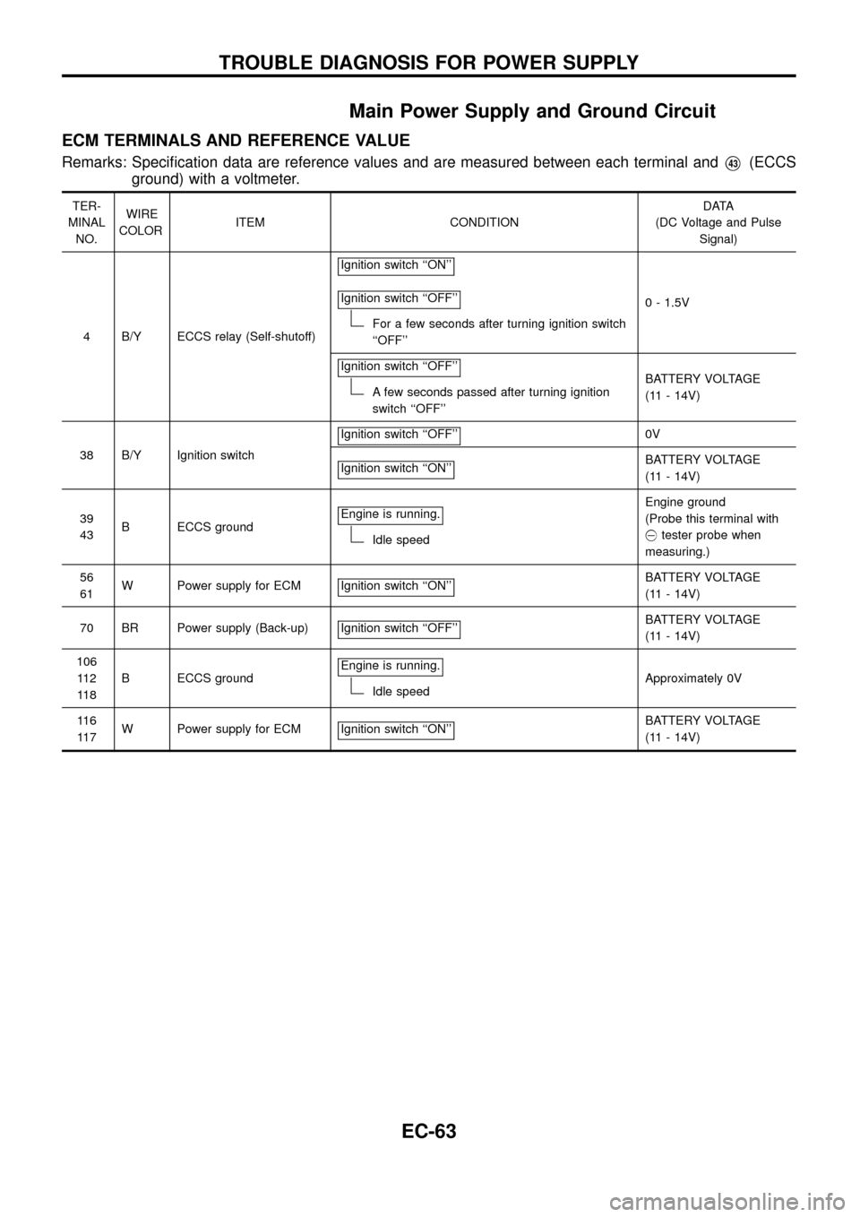
Main Power Supply and Ground Circuit
ECM TERMINALS AND REFERENCE VALUE
Remarks: Speci®cation data are reference values and are measured between each terminal andV43(ECCS
ground) with a voltmeter.
TER-
MINAL
NO.WIRE
COLORITEM CONDITIONDATA
(DC Voltage and Pulse
Signal)
4 B/Y ECCS relay (Self-shutoff)Ignition switch ``ON''
Ignition switch ``OFF''
For a few seconds after turning ignition switch
``OFF''0 - 1.5V
Ignition switch ``OFF''
A few seconds passed after turning ignition
switch ``OFF''BATTERY VOLTAGE
(11 - 14V)
38 B/Y Ignition switchIgnition switch ``OFF''
0V
Ignition switch ``ON''
BATTERY VOLTAGE
(11 - 14V)
39
43B ECCS groundEngine is running.
Idle speedEngine ground
(Probe this terminal with
@tester probe when
measuring.)
56
61W Power supply for ECM Ignition switch ``ON''
BATTERY VOLTAGE
(11 - 14V)
70 BR Power supply (Back-up) Ignition switch ``OFF''
BATTERY VOLTAGE
(11 - 14V)
106
11 2
11 8B ECCS groundEngine is running.
Idle speedApproximately 0V
11 6
11 7W Power supply for ECM Ignition switch ``ON''
BATTERY VOLTAGE
(11 - 14V)
TROUBLE DIAGNOSIS FOR POWER SUPPLY
EC-63