1998 NISSAN PATROL display
[x] Cancel search: displayPage 3 of 192
Alphabetical & Numerical Index for DTC
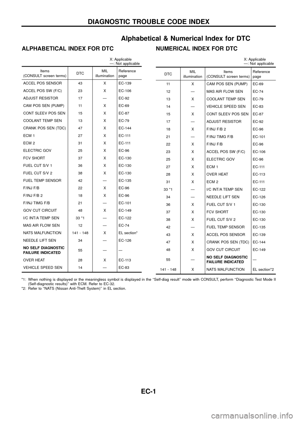
ALPHABETICAL INDEX FOR DTC
X: Applicable
Ð: Not applicable
Items
(CONSULT screen terms) DTCMIL
illumination Reference
page
ACCEL POS SENSOR 43 X EC-139
ACCEL POS SW (F/C) 23 X EC-106
ADJUST RESISTOR 17 Ð EC-92
CAM POS SEN (PUMP) 11 X EC-69
CONT SLEEV POS SEN 15 X EC-87
COOLANT TEMP SEN 13 X EC-79
CRANK POS SEN (TDC) 47 X EC-144
ECM 1 27 X EC-111
ECM 2 31 X EC-111
ELECTRIC GOV 25 X EC-96
FCV SHORT 37 X EC-130
FUEL CUT S/V 1 36 X EC-130
FUEL CUT S/V 2 38 X EC-130
FUEL TEMP SENSOR 42 Ð EC-135
F/INJ F/B 22 X EC-96
F/INJ F/B 2 18 X EC-96
F/INJ TIMG F/B 21 Ð EC-101
GOV CUT CIRCUIT 48 X EC-149
I/C INT/A TEMP SEN 33 *1 Ð EC-122
MAS AIR FLOW SEN 12 Ð EC-74
NATS MALFUNCTION 141 - 148 X EL section*
NEEDLE LIFT SEN 34 Ð EC-126
NO SELF DIAGNOSTIC
FAILURE INDICATED 55 Ð Ð
OVER HEAT 28 X EC-113
VEHICLE SPEED SEN 14 Ð EC-83
NUMERICAL INDEX FOR DTC
X: Applicable
Ð: Not applicable
DTC MIL
illumination Items
(CONSULT screen terms) Reference
page
11 X CAM POS SEN (PUMP) EC-69
12 Ð MAS AIR FLOW SEN EC-74
13 X COOLANT TEMP SEN EC-79
14 Ð VEHICLE SPEED SEN EC-83
15 X CONT SLEEV POS SEN EC-87
17 Ð ADJUST RESISTOR EC-92
18 X F/INJ F/B 2 EC-96
21 Ð F/INJ TIMG F/B EC-101
22 X F/INJ F/B EC-96
23 X ACCEL POS SW (F/C) EC-106
25 X ELECTRIC GOV EC-96
27 X ECM 1 EC-111
28 X OVER HEAT EC-113
31 X ECM 2 EC-111
33 *1 Ð I/C INT/A TEMP SEN EC-122 34 Ð NEEDLE LIFT SEN EC-126
36 X FUEL CUT S/V 1 EC-130
37 X FCV SHORT EC-130
38 X FUEL CUT S/V 2 EC-130
42 Ð FUEL TEMP SENSOR EC-135
43 X ACCEL POS SENSOR EC-139
47 X CRANK POS SEN (TDC) EC-144
48 X GOV CUT CIRCUIT EC-149
55 Ð NO SELF DIAGNOSTIC
FAILURE INDICATED Ð
141 - 148 X NATS MALFUNCTION EL section*2
*1: When nothing is displayed or the meaningless symbol is displayed in the ``Self-diag result'' mode with CONSULT, perform ``Diagnostic Test Mode II (Self-diagnostic results)'' with ECM. Refer to EC-32.
*2: Refer to ``NATS (Nissan Anti-Theft System)'' in EL section.
DIAGNOSTIC TROUBLE CODE INDEX
EC-1
Page 8 of 192
Precautions
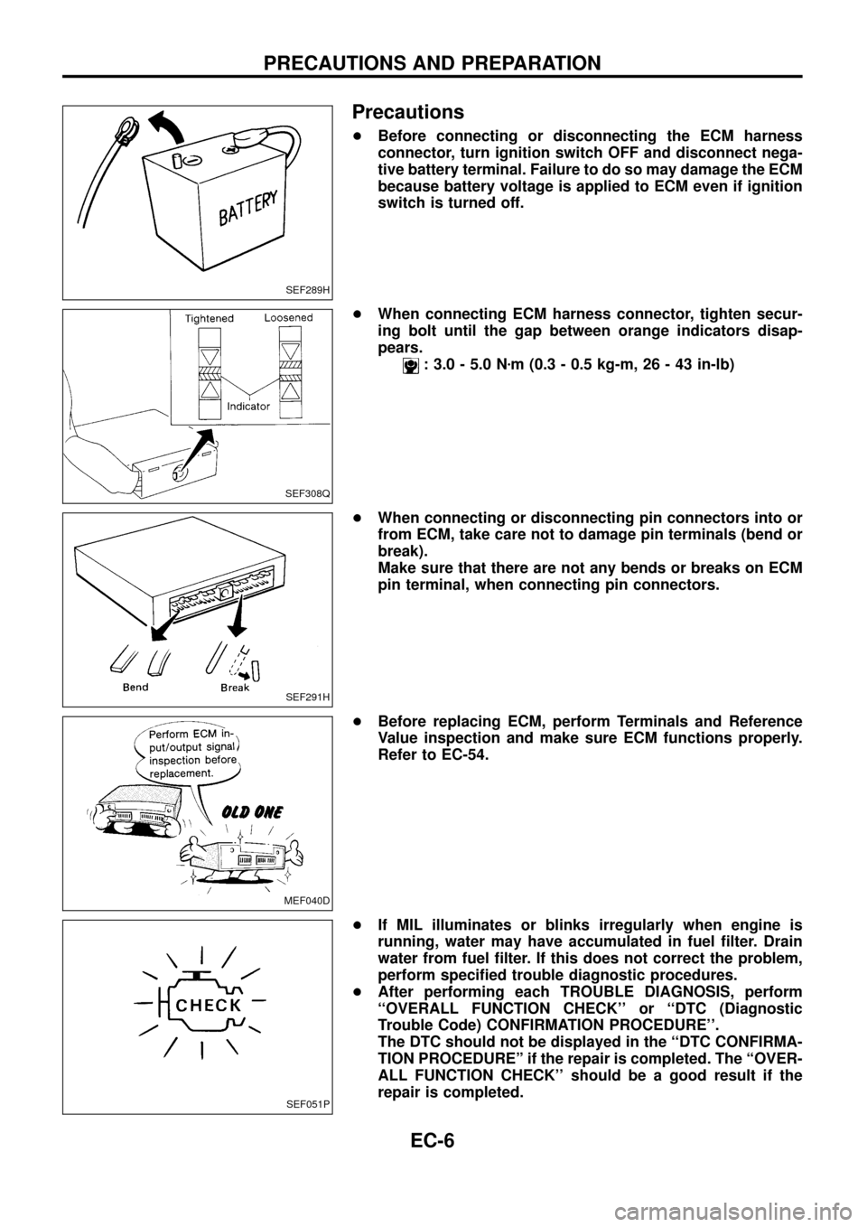
+Before connecting or disconnecting the ECM harness
connector, turn ignition switch OFF and disconnect nega-
tive battery terminal. Failure to do so may damage the ECM
because battery voltage is applied to ECM even if ignition
switch is turned off.
+When connecting ECM harness connector, tighten secur-
ing bolt until the gap between orange indicators disap-
pears.
: 3.0 - 5.0 Nzm (0.3 - 0.5 kg-m, 26 - 43 in-lb)
+When connecting or disconnecting pin connectors into or
from ECM, take care not to damage pin terminals (bend or
break).
Make sure that there are not any bends or breaks on ECM
pin terminal, when connecting pin connectors.
+Before replacing ECM, perform Terminals and Reference
Value inspection and make sure ECM functions properly.
Refer to EC-54.
+If MIL illuminates or blinks irregularly when engine is
running, water may have accumulated in fuel ®lter. Drain
water from fuel ®lter. If this does not correct the problem,
perform speci®ed trouble diagnostic procedures.
+After performing each TROUBLE DIAGNOSIS, perform
``OVERALL FUNCTION CHECK'' or ``DTC (Diagnostic
Trouble Code) CONFIRMATION PROCEDURE''.
The DTC should not be displayed in the ``DTC CONFIRMA-
TION PROCEDUREº if the repair is completed. The ``OVER-
ALL FUNCTION CHECK'' should be a good result if the
repair is completed.
SEF289H
SEF308Q
SEF291H
MEF040D
SEF051P
PRECAUTIONS AND PREPARATION
EC-6
Page 36 of 192
DIAGNOSTIC TEST MODE IÐBULB CHECK
In this mode, the MALFUNCTION INDICATOR LAMP on the instrument panel should stay ON. If it remains
OFF, check the bulb. Refer to EL section (``WARNING LAMPS AND CHIME'') or see EC-188.
DIAGNOSTIC TEST MODE IÐMALFUNCTION WARNING
MALFUNCTION
INDICATOR LAMPCondition
ONWhen the malfunction is detected or the ECM's CPU is malfunctioning. (Refer to ``MIL Illumination'' of the
``DIAGNOSTIC TROUBLE CODE INDEX'', EC-1.)
OFF No malfunction.
+These Diagnostic Trouble Code Numbers are clari®ed in Diagnostic Test Mode II (SELF-DIAGNOSTIC
RESULTS).
DIAGNOSTIC TEST MODE IIÐSELF-DIAGNOSTIC RESULTS
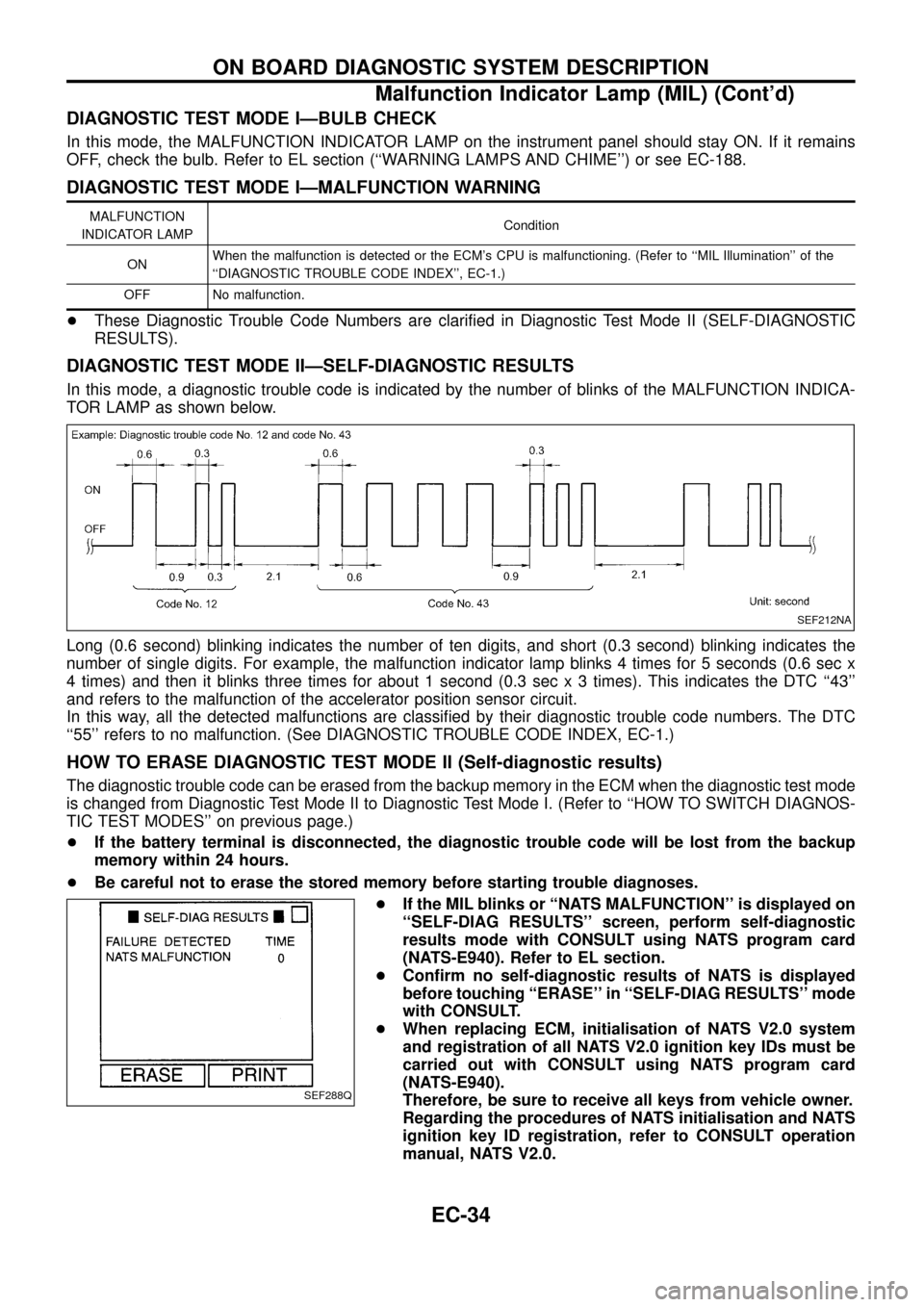
In this mode, a diagnostic trouble code is indicated by the number of blinks of the MALFUNCTION INDICA-
TOR LAMP as shown below.
Long (0.6 second) blinking indicates the number of ten digits, and short (0.3 second) blinking indicates the
number of single digits. For example, the malfunction indicator lamp blinks 4 times for 5 seconds (0.6 sec x
4 times) and then it blinks three times for about 1 second (0.3 sec x 3 times). This indicates the DTC ``43''
and refers to the malfunction of the accelerator position sensor circuit.
In this way, all the detected malfunctions are classi®ed by their diagnostic trouble code numbers. The DTC
``55'' refers to no malfunction. (See DIAGNOSTIC TROUBLE CODE INDEX, EC-1.)
HOW TO ERASE DIAGNOSTIC TEST MODE II (Self-diagnostic results)
The diagnostic trouble code can be erased from the backup memory in the ECM when the diagnostic test mode
is changed from Diagnostic Test Mode II to Diagnostic Test Mode I. (Refer to ``HOW TO SWITCH DIAGNOS-
TIC TEST MODES'' on previous page.)
+If the battery terminal is disconnected, the diagnostic trouble code will be lost from the backup
memory within 24 hours.
+Be careful not to erase the stored memory before starting trouble diagnoses.
+If the MIL blinks or ``NATS MALFUNCTION'' is displayed on
``SELF-DIAG RESULTS'' screen, perform self-diagnostic
results mode with CONSULT using NATS program card
(NATS-E940). Refer to EL section.
+Con®rm no self-diagnostic results of NATS is displayed
before touching ``ERASE'' in ``SELF-DIAG RESULTS'' mode
with CONSULT.
+When replacing ECM, initialisation of NATS V2.0 system
and registration of all NATS V2.0 ignition key IDs must be
carried out with CONSULT using NATS program card
(NATS-E940).
Therefore, be sure to receive all keys from vehicle owner.
Regarding the procedures of NATS initialisation and NATS
ignition key ID registration, refer to CONSULT operation
manual, NATS V2.0.
SEF212NA
SEF288Q
ON BOARD DIAGNOSTIC SYSTEM DESCRIPTION
Malfunction Indicator Lamp (MIL) (Cont'd)
EC-34
Page 37 of 192
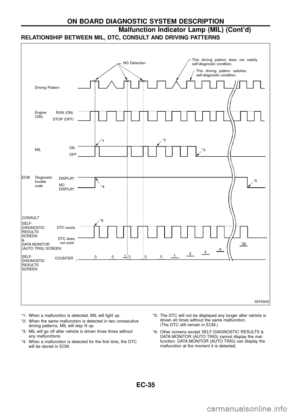
RELATIONSHIP BETWEEN MIL, DTC, CONSULT AND DRIVING PATTERNS
*1: When a malfunction is detected, MIL will light up.
*2: When the same malfunction is detected in two consecutive
driving patterns, MIL will stay lit up.
*3: MIL will go off after vehicle is driven three times without
any malfunctions.
*4: When a malfunction is detected for the ®rst time, the DTC
will be stored in ECM.*5: The DTC will not be displayed any longer after vehicle is
driven 40 times without the same malfunction.
(The DTC still remain in ECM.)
*6: Other screens except SELF-DIAGNOSTIC RESULTS &
DATA MONITOR (AUTO TRIG) cannot display the mal-
function. DATA MONITOR (AUTO TRIG) can display the
malfunction at the moment it is detected.
SEF659S
RUN (ON)
STOP (OFF)
ON
OFF
DISPLAY
NO
DISPLAY
DTC exists
DTC does
not exist
COUNTER Driving Pattern
Engine
(GN)
MIL
ECM Diagnostic
trouble
code
CONSULT
SELF-
DIAGNOSTIC
RESULTS
SCREEN
&
DATA MONITOR
(AUTO TRIG) SCREEN
SELF-
DIAGNOSTIC
RESULTS
SCREENNG DetectionThis driving pattern does not satisfy
self-diagnostic condition.
This driving pattern satis®es
self-diagnostic condition.
ON BOARD DIAGNOSTIC SYSTEM DESCRIPTION
Malfunction Indicator Lamp (MIL) (Cont'd)
EC-35
Page 40 of 192
![NISSAN PATROL 1998 Y61 / 5.G Engine Control Workshop Manual SELF-DIAGNOSTIC MODE
Regarding items detected in ``SELF-DIAG RESULTS mode, refer to ``DIAGNOSTIC TROUBLE CODE
INDEX, EC-1.
DATA MONITOR MODE
Monitored item
[Unit]ECM
input
signalsMain
signalsDescr NISSAN PATROL 1998 Y61 / 5.G Engine Control Workshop Manual SELF-DIAGNOSTIC MODE
Regarding items detected in ``SELF-DIAG RESULTS mode, refer to ``DIAGNOSTIC TROUBLE CODE
INDEX, EC-1.
DATA MONITOR MODE
Monitored item
[Unit]ECM
input
signalsMain
signalsDescr](/manual-img/5/617/w960_617-39.png)
SELF-DIAGNOSTIC MODE
Regarding items detected in ``SELF-DIAG RESULTS'' mode, refer to ``DIAGNOSTIC TROUBLE CODE
INDEX'', EC-1.
DATA MONITOR MODE
Monitored item
[Unit]ECM
input
signalsMain
signalsDescription Remarks
CKPSzRPM
(TDC) [rpm]
jj
+The engine speed computed from the
crankshaft position sensor (TDC) signal
is displayed.
CKPSzRPM
(REF) [rpm]
jj
+The engine speed [determined by the
time between pulses from the crankshaft
position sensor (TDC) signal] is dis-
played.
CMPSzRPM -
PUMP [rpm]
jj
+The engine speed computed from the
camshaft position sensor (PUMP) signal
is displayed.
COOLAN TEMP/S
[ÉC] or [ÉF]
jj
+The engine coolant temperature (deter-
mined by the signal voltage of the engine
coolant temperature sensor) is displayed.+When the engine coolant temperature
sensor is open or short-circuited, ECM
enters fail-safe mode. The engine cool-
ant temperature determined by the ECM
is displayed.
VHCL SPEED SE
[km/h] or [mph]
jj+The vehicle speed computed from the
vehicle speed sensor signal is displayed.
FUEL TEMP SEN
[ÉC] or [ÉF]
jj
+The fuel temperature (determined by the
signal voltage of the fuel temperature
sensor) is displayed.
ACCEL POS SEN [V]
jj+The accelerator position sensor signal
voltage is displayed.
FULL ACCEL SW
[ON/OFF]
jj+Indicates [ON/OFF] condition from the
accelerator position switch signal.
ACCEL SW (FC)
[OPEN/CLOSE]
jj+Indicates [OPEN/CLOSE] condition from
the accelerator switch (FC) signal.
OFF ACCEL SW
[ON/OFF]
jj+Indicates [ON/OFF] condition from the
accelerator position switch signal.
C/SLEEV POS/S [V]
jj+The control sleeve position sensor signal
voltage is displayed.
BATTERY VOLT [V]
jj+The power supply voltage of ECM is dis-
played.
P/N POSI SW
[ON/OFF]
jj+Indicates [ON/OFF] condition from the
park/neutral position switch signal.
START SIGNAL
[ON/OFF]
jj+Indicates [ON/OFF] condition from the
starter signal.+After starting the engine, [OFF] is dis-
played regardless of the starter signal.
NOTE:
Any monitored item that does not match the vehicle being diagnosed is deleted from the display automatically.
ON BOARD DIAGNOSTIC SYSTEM DESCRIPTION
CONSULT (Cont'd)
EC-38
Page 41 of 192
![NISSAN PATROL 1998 Y61 / 5.G Engine Control Workshop Manual Monitored item
[Unit]ECM
input
signalsMain
signalsDescription Remarks
AIR COND SIG
[ON/OFF]
jj
+Indicates [ON/OFF] condition of the air
conditioner switch as determined by the
air conditioner signal.
NISSAN PATROL 1998 Y61 / 5.G Engine Control Workshop Manual Monitored item
[Unit]ECM
input
signalsMain
signalsDescription Remarks
AIR COND SIG
[ON/OFF]
jj
+Indicates [ON/OFF] condition of the air
conditioner switch as determined by the
air conditioner signal.](/manual-img/5/617/w960_617-40.png)
Monitored item
[Unit]ECM
input
signalsMain
signalsDescription Remarks
AIR COND SIG
[ON/OFF]
jj
+Indicates [ON/OFF] condition of the air
conditioner switch as determined by the
air conditioner signal.
IGN SW
[ON/OFF]
jj+Indicates [ON/OFF] condition from igni-
tion switch signal.
MAS AIR/FL SE [V]
jj+The signal voltage of the mass air ¯ow
sensor is displayed.+When the engine is stopped, a certain
value is indicated.
ACT INJ TIMG [É]
jj
+The actual injection timing angle deter-
mined by the ECM (an approximate
average angle between injection start
and end from TDC) is displayed.
INJ TIMG C/V [%]+Indicates the duty ratio of fuel injection
timing control valve.
DECELER F/CUT
[ON/OFF]
j
+Indicates [ON/OFF] condition from decel-
eration fuel cut signal.+When the accelerator pedal is released
quickly with engine speed at 3,000 rpm
or more, ``ON'' is displayed.
FUEL CUT S/V
[ON/OFF]
j
+The control condition of the fuel cut sole-
noid valve (determined by ECM accord-
ing to the input signal) is indicted.
+OFF ... Fuel cut solenoid valve is not
operating.
ON ... Fuel cut solenoid valve is operat-
ing.+When the fuel cut solenoid valve is not
operating, fuel is not supplied to injection
nozzles.
GLOW RLY [ON/OFF]
j
+The glow relay control condition (deter-
mined by ECM according to the input
signal) is displayed.
COOLING FAN
[LOW/HI/OFF]
j
+Indicates the control condition of the
cooling fans (determined by ECM
according to the input signal).
+LOW ... Operates at low speed.
HI ... Operates at high speed.
OFF ... Stopped.
I/C FAN RLY
[ON/OFF]
j
+Indicates the control condition of the
charge air cooler fan (determined by
ECM according to the input signals).
EGRC SOL/V A
[ON/OFF]+The control condition of the EGRC-sole-
noid valve A (determined by ECM
according to the input signal) is indi-
cated.
+OFF ... EGRC-solenoid valve A is not
operating.
ON ... EGRC-solenoid valve A is operat-
ing.
EGRC SOL/V B
[ON/OFF]+The control condition of the EGRC-sole-
noid valve B (determined by ECM
according to the input signal) is indi-
cated.
+OFF ... EGRC-solenoid valve B is not
operating.
ON ... EGRC-solenoid valve B is operat-
ing.
THROT RLY
[ON/OFF]+The control condition of the throttle con-
trol solenoid valve (determined by ECM
according to the input signal) is indi-
cated.
+OFF ... Throttle control solenoid valve is
not operating.
ON ... Throttle control solenoid valve is
operating.
ON BOARD DIAGNOSTIC SYSTEM DESCRIPTION
CONSULT (Cont'd)
EC-39
Page 43 of 192
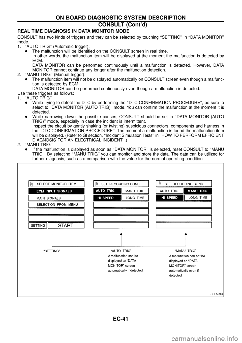
REAL TIME DIAGNOSIS IN DATA MONITOR MODE
CONSULT has two kinds of triggers and they can be selected by touching ``SETTING'' in ``DATA MONITOR''
mode.
1. ``AUTO TRIG'' (Automatic trigger):
+The malfunction will be identi®ed on the CONSULT screen in real time.
In other words, the malfunction item will be displayed at the moment the malfunction is detected by
ECM.
DATA MONITOR can be performed continuously until a malfunction is detected. However, DATA
MONITOR cannot continue any longer after the malfunction detection.
2. ``MANU TRIG'' (Manual trigger):
+The malfunction item will not be displayed automatically on CONSULT screen even though a malfunc-
tion is detected by ECM.
DATA MONITOR can be performed continuously even though a malfunction is detected.
Use these triggers as follows:
1. ``AUTO TRIG''
+While trying to detect the DTC by performing the ``DTC CONFIRMATION PROCEDURE'', be sure to
select to ``DATA MONITOR (AUTO TRIG)'' mode. You can con®rm the malfunction at the moment it is
detected.
+While narrowing down the possible causes, CONSULT should be set in ``DATA MONITOR (AUTO
TRIG)'' mode, especially in case the incident is intermittent.
Inspect the circuit by gently shaking (or twisting) suspicious connectors, components and harness in
the ``DTC CONFIRMATION PROCEDURE''. The moment a malfunction is found the malfunction item
will be displayed. (Refer to GI section, ``Incident Simulation Tests'' in ``HOW TO PERFORM EFFICIENT
DIAGNOSIS FOR AN ELECTRICAL INCIDENT''.)
2. ``MANU TRIG''
+If the malfunction is displayed as soon as ``DATA MONITOR'' is selected, reset CONSULT to ``MANU
TRIG''. By selecting ``MANU TRIG'' you can monitor and store the data. The data can be utilized for
further diagnosis, such as a comparison with the value for the normal operating condition.
SEF529Q
ON BOARD DIAGNOSTIC SYSTEM DESCRIPTION
CONSULT (Cont'd)
EC-41
Page 47 of 192
Description for Work Flow
STEP DESCRIPTION
STEP IGet detailed information about the conditions and the environment when the incident/symptom occurred using the
``DIAGNOSTIC WORKSHEET'' as shown on EC-43.
STEP IIBefore con®rming the concern, check and write down (print out using CONSULT) the Diagnostic Trouble Code
(DTC), then erase the code. Refer to EC-30.
Study the relationship between the cause, speci®ed by DTC, and the symptom described by the customer. (The
``Symptom Matrix Chart'' will be useful. Refer to EC-48.)
STEP IIITry to con®rm the symptom and under what conditions the incident occurs.
The ``DIAGNOSTIC WORK SHEET'' is useful to verify the incident. Connect CONSULT to the vehicle in DATA
MONITOR (AUTO TRIG) mode and check real time diagnosis results.
If the incident cannot be veri®ed, perform INCIDENT SIMULATION TESTS. Refer to GI section.
If the malfunction code is detected, skip STEP IV and perform STEP V.
STEP IVTry to detect the Diagnostic Trouble Code (DTC) by driving in (or performing) the ``DTC CONFIRMATION PROCE-
DURE''. Check and read the DTC by using CONSULT.
During the DTC veri®cation, be sure to connect CONSULT to the vehicle in DATA MONITOR (AUTO TRIG) mode
and check real time diagnosis results.
If the incident cannot be veri®ed, perform INCIDENT SIMULATION TESTS. Refer to GI section.
In case the ``DTC CONFIRMATION PROCEDURE'' is not available, perform the ``OVERALL FUNCTION CHECK''
instead. The DTC cannot be displayed by this check, however, this simpli®ed ``check'' is an effective alternative.
The ``NG'' result of the ``OVERALL FUNCTION CHECK'' is the same as the DTC detection.
STEP VTake the appropriate action based on the results of STEP I through IV.
If the malfunction code is indicated, proceed to TROUBLE DIAGNOSIS FOR DTC XX.
If the normal code is indicated, proceed to the BASIC INSPECTION. Refer to EC-46. Then perform inspections
according to the Symptom Matrix Chart. Refer to EC-48.
STEP VIIdentify where to begin diagnosis based on the relationship study between symptom and possible causes. Inspect
the system for mechanical binding, loose connectors or wiring damage using (tracing) ``Harness Layouts''.
Gently shake the related connectors, components or wiring harness with CONSULT set in ``DATA MONITOR
(AUTO TRIG)'' mode.
Check the voltage of the related ECM terminals or monitor the output data from the related sensors with CON-
SULT. Refer to EC-54.
The ``DIAGNOSTIC PROCEDURE'' in EC section contains a description based on open circuit inspection. A short
circuit inspection is also required for the circuit check in the DIAGNOSTIC PROCEDURE. For details, refer to GI
section (``Circuit Inspection'', ``HOW TO PERFORM EFFICIENT DIAGNOSIS FOR AN ELECTRICAL INCIDENT'').
Repair or replace the malfunction parts.
STEP VIIOnce you have repaired the circuit or replaced a component, you need to run the engine in the same conditions
and circumstances which resulted in the customer's initial complaint.
Perform the ``DTC CONFIRMATION PROCEDURE'' and con®rm the normal code (Diagnostic trouble code No. 55)
is detected. If the incident is still detected in the ®nal check, perform STEP VI by using a different method from the
previous one.
Before returning the vehicle to the customer, be sure to erase the unnecessary (already ®xed) DTC in ECM. (Refer
to EC-30.)
TROUBLE DIAGNOSIS Ð Work Flow
EC-45