1998 NISSAN PATROL turn signal
[x] Cancel search: turn signalPage 170 of 192
jA
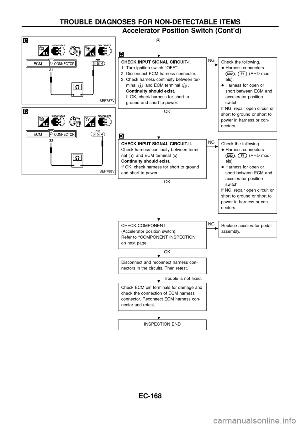
CHECK INPUT SIGNAL CIRCUIT-I.
1. Turn ignition switch ``OFF''.
2. Disconnect ECM harness connector.
3. Check harness continuity between ter-
minal
V6and ECM terminalV31.
Continuity should exist.
If OK, check harness for short to
ground and short to power.
OK
cNG
Check the following.
+Harness connectors
M52,F7(RHD mod-
els)
+Harness for open or
short between ECM and
accelerator position
switch
If NG, repair open circuit or
short to ground or short to
power in harness or con-
nectors.
CHECK INPUT SIGNAL CIRCUIT-II.
Check harness continuity between termi-
nal
V4and ECM terminalV32.
Continuity should exist.
If OK, check harness for short to ground
and short to power.
OK
cNG
Check the following.
+Harness connectors
M52,F7(RHD mod-
els)
+Harness for open or
short between ECM and
accelerator position
switch
If NG, repair open circuit or
short to ground or short to
power in harness or con-
nectors.
CHECK COMPONENT
(Accelerator position switch).
Refer to ``COMPONENT INSPECTION''
on next page.
OK
cNG
Replace accelerator pedal
assembly.
Disconnect and reconnect harness con-
nectors in the circuits. Then retest.
Trouble is not ®xed.
Check ECM pin terminals for damage and
check the connection of ECM harness
connector. Reconnect ECM harness con-
nector and retest.
INSPECTION END
SEF787V
SEF788V
.
.
.
.
.
.
TROUBLE DIAGNOSES FOR NON-DETECTABLE ITEMS
Accelerator Position Switch (Cont'd)
EC-168
Page 173 of 192
When the gear position is in ``N'', neutral position switch is ``ON''.
The ECM detects the position because the continuity of the line (the
``ON'' signal) exists.
CONSULT REFERENCE VALUE IN DATA MONITOR MODE
Remarks: Speci®cation data are reference values.
MONITOR ITEM CONDITION SPECIFICATION
P/N POSI SW+Ignition switch: ONShift lever: Neutral/Park ON
Except above OFF
ECM TERMINALS AND REFERENCE VALUE
Remarks: Speci®cation data are reference values and are measured between each terminal andV43(ECCS
ground) with a voltmeter.
TER-
MINAL
NO.WIRE
COLORITEM CONDITIONDATA
(DC Voltage and Pulse
Signal)
22 P/BInhibitor switch/
Neutral position switchIgnition switch ``ON''
Gear position is ``N'' or ``P'' (A/T models).Gear position is ``Neutral'' (M/T models).Approximately 0V
Ignition switch ``ON''
Except the above gear positionBATTERY VOLTAGE
(11 - 14V)
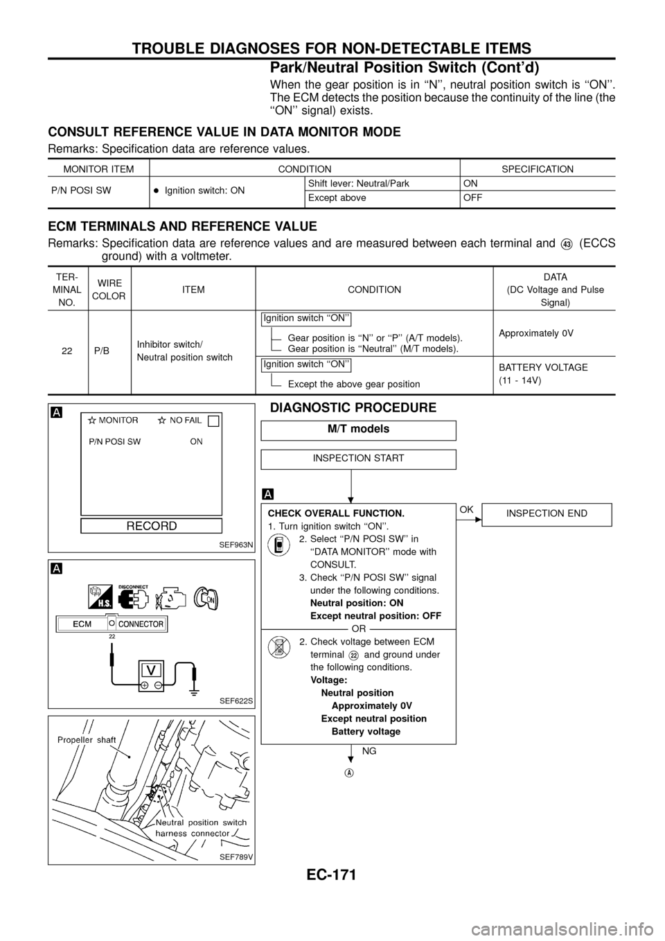
DIAGNOSTIC PROCEDURE
M/T models
INSPECTION START
CHECK OVERALL FUNCTION.
1. Turn ignition switch ``ON''.
2. Select ``P/N POSI SW'' in
``DATA MONITOR'' mode with
CONSULT.
3. Check ``P/N POSI SW'' signal
under the following conditions.
Neutral position: ON
Except neutral position: OFF
--------------------------------------------------------------------------------------------------------------------------------------OR--------------------------------------------------------------------------------------------------------------------------------------
2. Check voltage between ECM
terminal
V22and ground under
the following conditions.
Voltage:
Neutral position
Approximately 0V
Except neutral position
Battery voltage
NG
cOK
INSPECTION END
jA
SEF963N
SEF622S
SEF789V
.
.
TROUBLE DIAGNOSES FOR NON-DETECTABLE ITEMS
Park/Neutral Position Switch (Cont'd)
EC-171
Page 174 of 192
jA
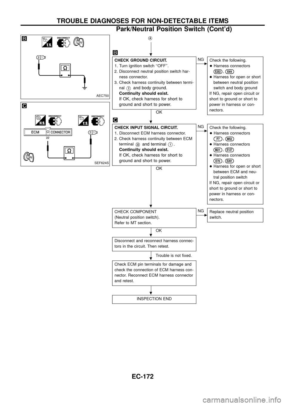
CHECK GROUND CIRCUIT.
1. Turn ignition switch ``OFF''.
2. Disconnect neutral position switch har-
ness connector.
3. Check harness continuity between termi-
nal
V2and body ground.
Continuity should exist.
If OK, check harness for short to
ground and short to power.
OK
cNG
Check the following.
+Harness connectors
E202,E69
+Harness for open or short
between neutral position
switch and body ground
If NG, repair open circuit or
short to ground or short to
power in harness or con-
nectors.
CHECK INPUT SIGNAL CIRCUIT.
1. Disconnect ECM harness connector.
2. Check harness continuity between ECM
terminal
V22and terminalV1.
Continuity should exist.
If OK, check harness for short to
ground and short to power.
OK
cNG
Check the following.
+Harness connectors
F7,M52
+Harness connectors
M21,E127
+Harness connectors
E70,E201
+Harness for open or short
between ECM and neu-
tral position switch
If NG, repair open circuit or
short to ground or short to
power in harness or con-
nectors.
CHECK COMPONENT
(Neutral position switch).
Refer to MT section.
OK
cNG
Replace neutral position
switch.
Disconnect and reconnect harness connec-
tors in the circuit. Then retest.
Trouble is not ®xed.
Check ECM pin terminals for damage and
check the connection of ECM harness con-
nector. Reconnect ECM harness connector
and retest.
INSPECTION END
AEC750
SEF624S
.
.
.
.
.
.
TROUBLE DIAGNOSES FOR NON-DETECTABLE ITEMS
Park/Neutral Position Switch (Cont'd)
EC-172
Page 175 of 192
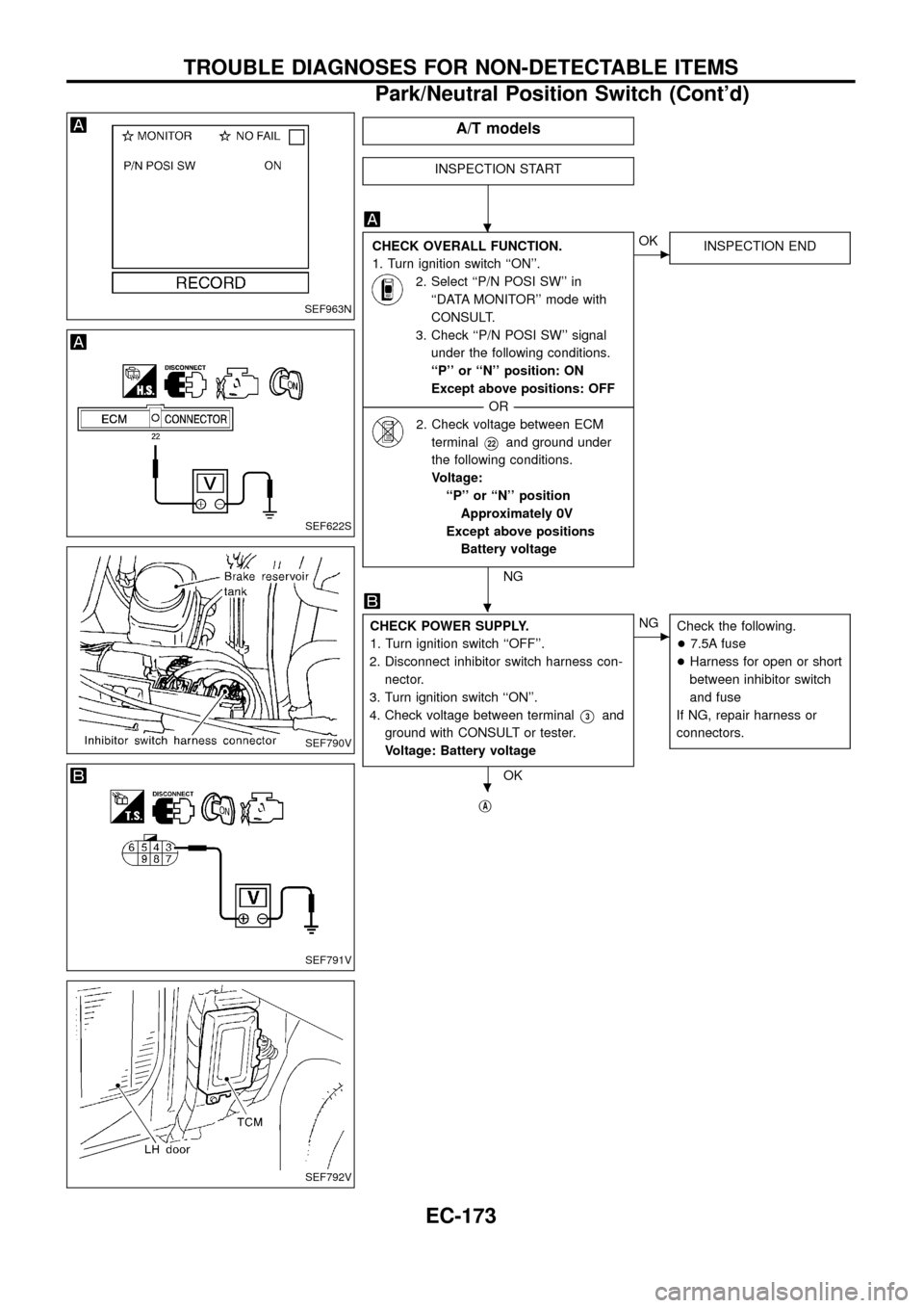
A/T models
INSPECTION START
CHECK OVERALL FUNCTION.
1. Turn ignition switch ``ON''.
2. Select ``P/N POSI SW'' in
``DATA MONITOR'' mode with
CONSULT.
3. Check ``P/N POSI SW'' signal
under the following conditions.
``P'' or ``N'' position: ON
Except above positions: OFF
--------------------------------------------------------------------------------------------------------------------------------------OR--------------------------------------------------------------------------------------------------------------------------------------
2. Check voltage between ECM
terminal
V22and ground under
the following conditions.
Voltage:
``P'' or ``N'' position
Approximately 0V
Except above positions
Battery voltage
NG
cOK
INSPECTION END
CHECK POWER SUPPLY.
1. Turn ignition switch ``OFF''.
2. Disconnect inhibitor switch harness con-
nector.
3. Turn ignition switch ``ON''.
4. Check voltage between terminal
V3and
ground with CONSULT or tester.
Voltage: Battery voltage
OK
cNG
Check the following.
+7.5A fuse
+Harness for open or short
between inhibitor switch
and fuse
If NG, repair harness or
connectors.
jA
SEF963N
SEF622S
SEF790V
SEF791V
SEF792V
.
.
.
TROUBLE DIAGNOSES FOR NON-DETECTABLE ITEMS
Park/Neutral Position Switch (Cont'd)
EC-173
Page 176 of 192
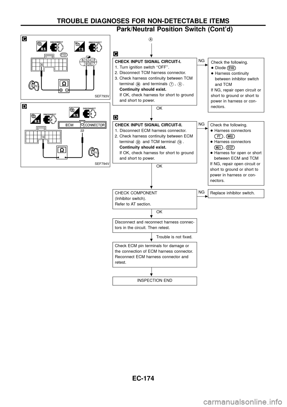
jA
CHECK INPUT SIGNAL CIRCUIT-I.
1. Turn ignition switch ``OFF''.
2. Disconnect TCM harness connector.
3. Check harness continuity between TCM
terminal
V36and terminalsV7,V9.
Continuity should exist.
If OK, check harness for short to ground
and short to power.
OK
cNG
Check the following.
+Diode
E103
+Harness continuity
between inhibitor switch
and TCM
If NG, repair open circuit or
short to ground or short to
power in harness or con-
nectors.
CHECK INPUT SIGNAL CIRCUIT-II.
1. Disconnect ECM harness connector.
2. Check harness continuity between ECM
terminal
V22and TCM terminalV14.
Continuity should exist.
If OK, check harness for short to ground
and short to power.
OK
cNG
Check the following.
+Harness connectors
F7,M52
+Harness connectors
M21,E127
+Harness for open or short
between ECM and TCM
If NG, repair open circuit or
short to ground or short to
power in harness or con-
nectors.
CHECK COMPONENT
(Inhibitor switch).
Refer to AT section.
OK
cNG
Replace inhibitor switch.
Disconnect and reconnect harness connec-
tors in the circuit. Then retest.
Trouble is not ®xed.
Check ECM pin terminals for damage or
the connection of ECM harness connector.
Reconnect ECM harness connector and
retest.
INSPECTION END
SEF793V
SEF794V
.
.
.
.
.
.
TROUBLE DIAGNOSES FOR NON-DETECTABLE ITEMS
Park/Neutral Position Switch (Cont'd)
EC-174
Page 179 of 192
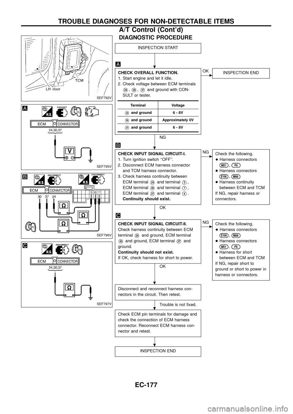
DIAGNOSTIC PROCEDURE
INSPECTION START
CHECK OVERALL FUNCTION.
1. Start engine and let it idle.
2. Check voltage between ECM terminals
V24,V30,V37and ground with CON-
SULT or tester.
NG
cOK
INSPECTION END
CHECK INPUT SIGNAL CIRCUIT-I.
1. Turn ignition switch ``OFF''.
2. Disconnect ECM harness connector
and TCM harness connector.
3. Check harness continuity between
ECM terminal
V24and terminalV5,
ECM terminal
V30and terminalV7,
ECM terminal
V37and terminalV6.
Continuity should exist.
OK
cNG
Check the following.
+Harness connectors
M51,F6
+Harness connectors
E106,M88
+Harness continuity
between ECM and TCM
If NG, repair harness or
connectors.
CHECK INPUT SIGNAL CIRCUIT-II.
Check harness continuity between ECM
terminal
V24and ground, ECM terminal
V30and ground, ECM terminalV37and
ground.
Continuity should not exist.
If OK, check harness for short to power.
OK
cNG
Check the following.
+Harness connectors
E106,M88
+Harness connectors
M51,F6
+Harness for short
between ECM and TCM
If NG, repair short to
ground or short to power in
harness or connectors.
Disconnect and reconnect harness con-
nectors in the circuit. Then retest.
Trouble is not ®xed.
Check ECM pin terminals for damage and
check the connection of ECM harness
connector. Reconnect ECM harness con-
nector and retest.
INSPECTION END
Terminal Voltage
V24and ground 6 - 8V
V30and ground Approximately 0V
V37and ground 6 - 8V
SEF792V
SEF795V
SEF796V
SEF797V
.
.
.
.
.
.
TROUBLE DIAGNOSES FOR NON-DETECTABLE ITEMS
A/T Control (Cont'd)
EC-177
Page 180 of 192
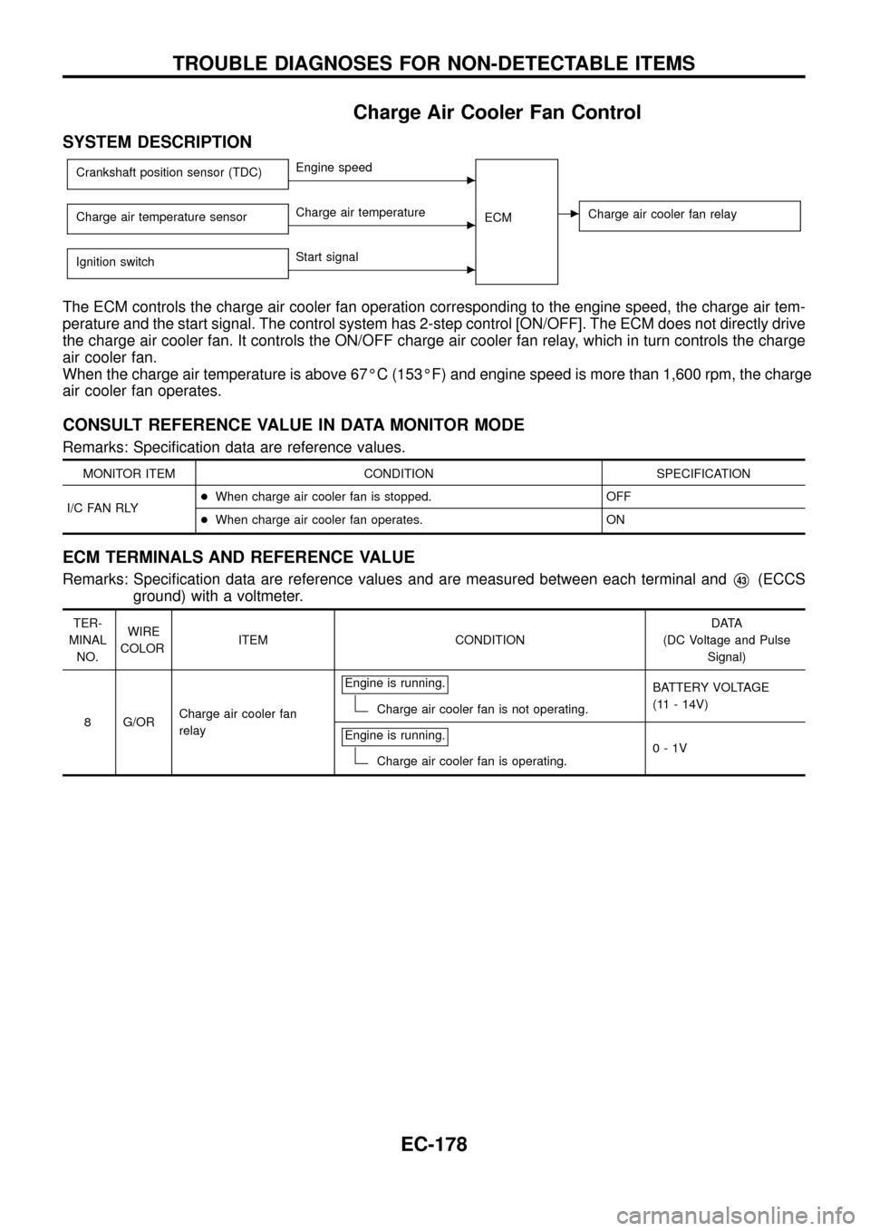
Charge Air Cooler Fan Control
SYSTEM DESCRIPTION
Crankshaft position sensor (TDC)cEngine speed
ECM
cCharge air cooler fan relayCharge air temperature sensorcCharge air temperature
Ignition switch
cStart signal
The ECM controls the charge air cooler fan operation corresponding to the engine speed, the charge air tem-
perature and the start signal. The control system has 2-step control [ON/OFF]. The ECM does not directly drive
the charge air cooler fan. It controls the ON/OFF charge air cooler fan relay, which in turn controls the charge
air cooler fan.
When the charge air temperature is above 67ÉC (153ÉF) and engine speed is more than 1,600 rpm, the charge
air cooler fan operates.
CONSULT REFERENCE VALUE IN DATA MONITOR MODE
Remarks: Speci®cation data are reference values.
MONITOR ITEM CONDITION SPECIFICATION
I/C FAN RLY+When charge air cooler fan is stopped. OFF
+When charge air cooler fan operates. ON
ECM TERMINALS AND REFERENCE VALUE
Remarks: Speci®cation data are reference values and are measured between each terminal andV43(ECCS
ground) with a voltmeter.
TER-
MINAL
NO.WIRE
COLORITEM CONDITIONDATA
(DC Voltage and Pulse
Signal)
8 G/ORCharge air cooler fan
relayEngine is running.
Charge air cooler fan is not operating.BATTERY VOLTAGE
(11 - 14V)
Engine is running.
Charge air cooler fan is operating.0-1V
TROUBLE DIAGNOSES FOR NON-DETECTABLE ITEMS
EC-178
Page 187 of 192
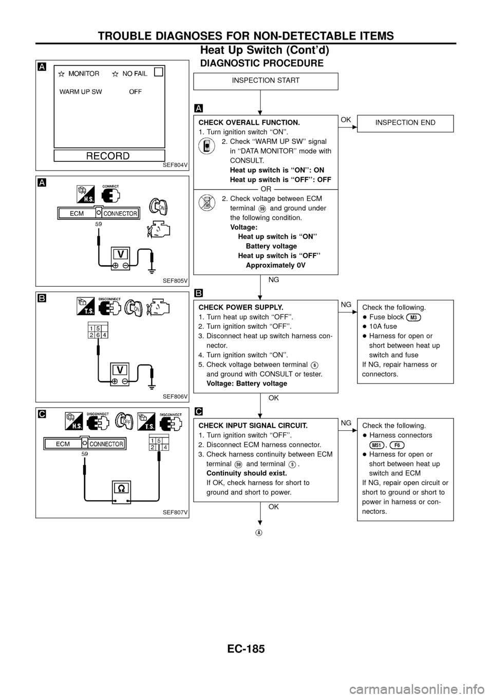
DIAGNOSTIC PROCEDURE
INSPECTION START
CHECK OVERALL FUNCTION.
1. Turn ignition switch ``ON''.
2. Check ``WARM UP SW'' signal
in ``DATA MONITOR'' mode with
CONSULT.
Heat up switch is ``ON'': ON
Heat up switch is ``OFF'': OFF
--------------------------------------------------------------------------------------------------------------------------------------OR--------------------------------------------------------------------------------------------------------------------------------------
2. Check voltage between ECM
terminal
V59and ground under
the following condition.
Voltage:
Heat up switch is ``ON''
Battery voltage
Heat up switch is ``OFF''
Approximately 0V
NG
cOK
INSPECTION END
CHECK POWER SUPPLY.
1. Turn heat up switch ``OFF''.
2. Turn ignition switch ``OFF''.
3. Disconnect heat up switch harness con-
nector.
4. Turn ignition switch ``ON''.
5. Check voltage between terminal
V6
and ground with CONSULT or tester.
Voltage: Battery voltage
OK
cNG
Check the following.
+Fuse block
M3
+10A fuse
+Harness for open or
short between heat up
switch and fuse
If NG, repair harness or
connectors.
CHECK INPUT SIGNAL CIRCUIT.
1. Turn ignition switch ``OFF''.
2. Disconnect ECM harness connector.
3. Check harness continuity between ECM
terminal
V59and terminalV5.
Continuity should exist.
If OK, check harness for short to
ground and short to power.
OK
cNG
Check the following.
+Harness connectors
M51,F6
+Harness for open or
short between heat up
switch and ECM
If NG, repair open circuit or
short to ground or short to
power in harness or con-
nectors.
jA
SEF804V
SEF805V
SEF806V
SEF807V
.
.
.
.
TROUBLE DIAGNOSES FOR NON-DETECTABLE ITEMS
Heat Up Switch (Cont'd)
EC-185