Page 61 of 192
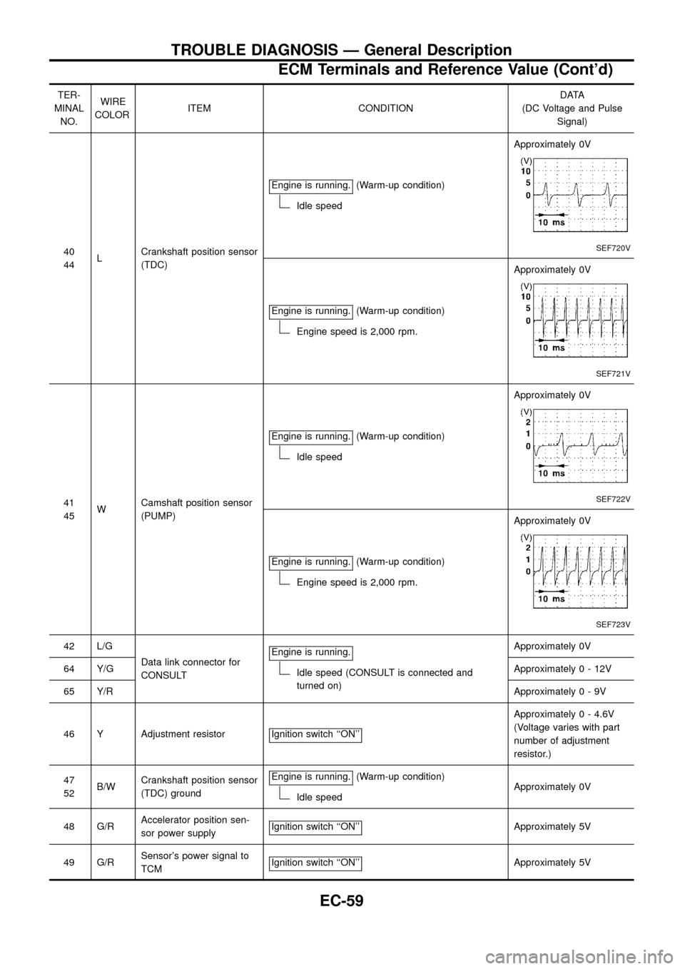
TER-
MINAL
NO.WIRE
COLORITEM CONDITIONDATA
(DC Voltage and Pulse
Signal)
40
44LCrankshaft position sensor
(TDC)Engine is running.
(Warm-up condition)
Idle speedApproximately 0V
SEF720V
Engine is running.(Warm-up condition)
Engine speed is 2,000 rpm.Approximately 0V
SEF721V
41
45WCamshaft position sensor
(PUMP)Engine is running.
(Warm-up condition)
Idle speedApproximately 0V
SEF722V
Engine is running.(Warm-up condition)
Engine speed is 2,000 rpm.Approximately 0V
SEF723V
42 L/G
Data link connector for
CONSULTEngine is running.
Idle speed (CONSULT is connected and
turned on)Approximately 0V
64 Y/GApproximately0-12V
65 Y/RApproximately0-9V
46 Y Adjustment resistor Ignition switch ``ON''
Approximately 0 - 4.6V
(Voltage varies with part
number of adjustment
resistor.)
47
52B/WCrankshaft position sensor
(TDC) groundEngine is running.
(Warm-up condition)
Idle speedApproximately 0V
48 G/RAccelerator position sen-
sor power supplyIgnition switch ``ON''
Approximately 5V
49 G/RSensor's power signal to
TCMIgnition switch ``ON''
Approximately 5V
TROUBLE DIAGNOSIS Ð General Description
ECM Terminals and Reference Value (Cont'd)
EC-59
Page 104 of 192
ON BOARD DIAGNOSIS LOGIC
Diagnostic
Trouble Code
No.Malfunction is detected when ....Check Items
(Possible cause)
21+Injection timing feedback system does not operate
properly. (This system consists essentially of ECM,
injection timing control valve and needle lift sensor.)+Harness or connectors
[Injection timing control valve, needle lift sensor,
crankshaft position sensor (TDC) circuits]
+Injection timing control valve
+Needle lift sensor
+Crankshaft position sensor (TDC)
+Air in fuel line
DIAGNOSTIC TROUBLE CODE CONFIRMATION
PROCEDURE
Note: If both DTC 21 and 34 or 47 are displayed, perform
TROUBLE DIAGNOSIS FOR DTC 34 or 47. (See EC-126
or EC-144.)
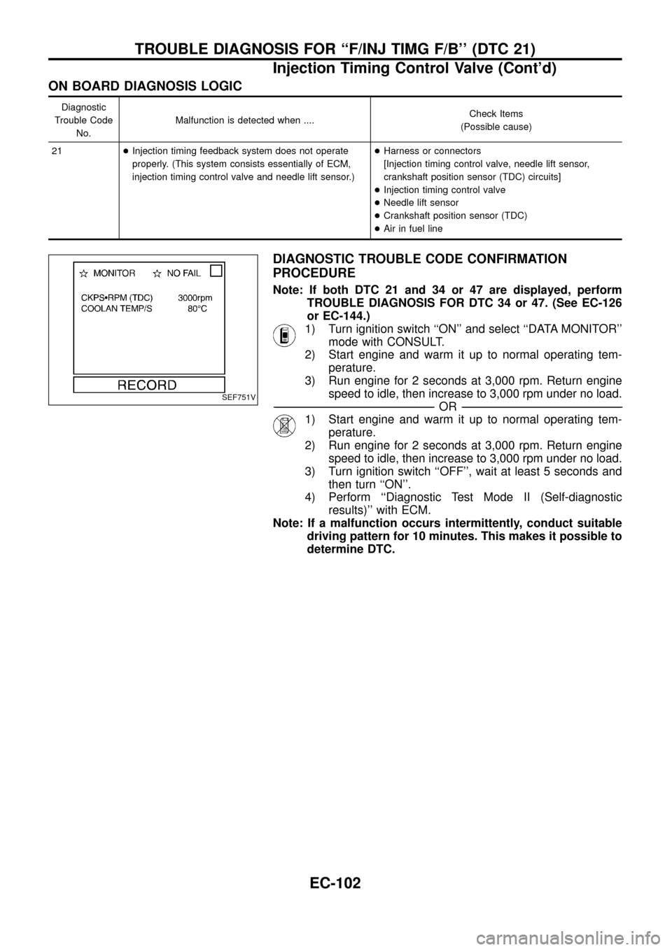
1) Turn ignition switch ``ON'' and select ``DATA MONITOR''
mode with CONSULT.
2) Start engine and warm it up to normal operating tem-
perature.
3) Run engine for 2 seconds at 3,000 rpm. Return engine
speed to idle, then increase to 3,000 rpm under no load.
-------------------------------------------------------------------------------------------------------------------------------------------------------------------------------------------------------------------------------------------------------OR-------------------------------------------------------------------------------------------------------------------------------------------------------------------------------------------------------------------------------------------------------
1) Start engine and warm it up to normal operating tem-
perature.
2) Run engine for 2 seconds at 3,000 rpm. Return engine
speed to idle, then increase to 3,000 rpm under no load.
3) Turn ignition switch ``OFF'', wait at least 5 seconds and
then turn ``ON''.
4) Perform ``Diagnostic Test Mode II (Self-diagnostic
results)'' with ECM.
Note: If a malfunction occurs intermittently, conduct suitable
driving pattern for 10 minutes. This makes it possible to
determine DTC.
SEF751V
TROUBLE DIAGNOSIS FOR ``F/INJ TIMG F/B'' (DTC 21)
Injection Timing Control Valve (Cont'd)
EC-102
Page 146 of 192
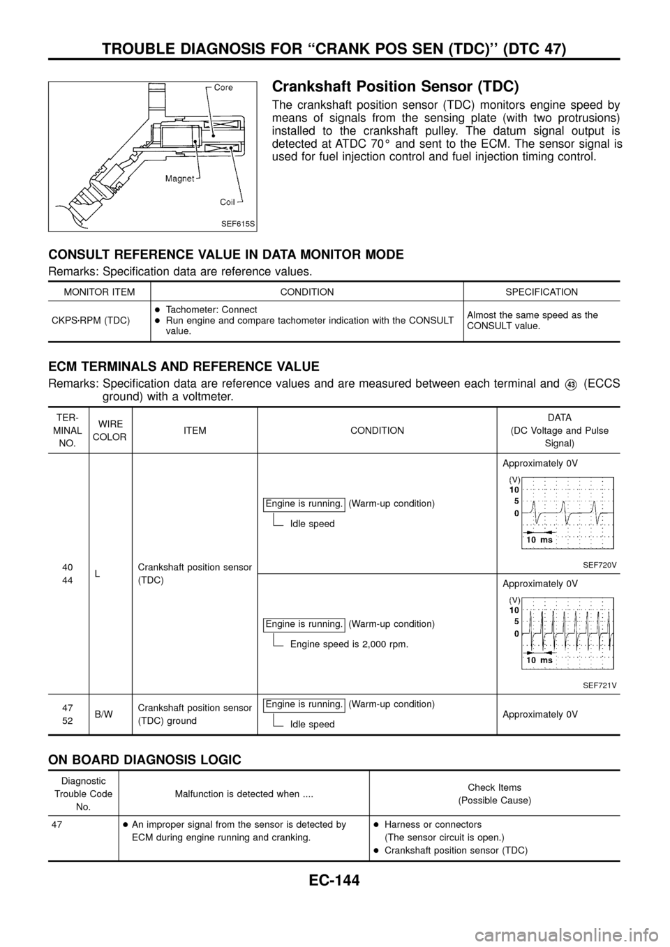
Crankshaft Position Sensor (TDC)
The crankshaft position sensor (TDC) monitors engine speed by
means of signals from the sensing plate (with two protrusions)
installed to the crankshaft pulley. The datum signal output is
detected at ATDC 70É and sent to the ECM. The sensor signal is
used for fuel injection control and fuel injection timing control.
CONSULT REFERENCE VALUE IN DATA MONITOR MODE
Remarks: Speci®cation data are reference values.
MONITOR ITEM CONDITION SPECIFICATION
CKPSzRPM (TDC)+Tachometer: Connect
+Run engine and compare tachometer indication with the CONSULT
value.Almost the same speed as the
CONSULT value.
ECM TERMINALS AND REFERENCE VALUE
Remarks: Speci®cation data are reference values and are measured between each terminal andV43(ECCS
ground) with a voltmeter.
TER-
MINAL
NO.WIRE
COLORITEM CONDITIONDATA
(DC Voltage and Pulse
Signal)
40
44LCrankshaft position sensor
(TDC)Engine is running.
(Warm-up condition)
Idle speedApproximately 0V
SEF720V
Engine is running.(Warm-up condition)
Engine speed is 2,000 rpm.Approximately 0V
SEF721V
47
52B/WCrankshaft position sensor
(TDC) groundEngine is running.(Warm-up condition)
Idle speedApproximately 0V
ON BOARD DIAGNOSIS LOGIC
Diagnostic
Trouble Code
No.Malfunction is detected when ....Check Items
(Possible Cause)
47+An improper signal from the sensor is detected by
ECM during engine running and cranking.+Harness or connectors
(The sensor circuit is open.)
+Crankshaft position sensor (TDC)
SEF615S
TROUBLE DIAGNOSIS FOR ``CRANK POS SEN (TDC)'' (DTC 47)
EC-144
Page 147 of 192
DIAGNOSTIC TROUBLE CODE CONFIRMATION
PROCEDURE
Before performing the following procedure, con®rm that bat-
tery voltage is more than 10V.
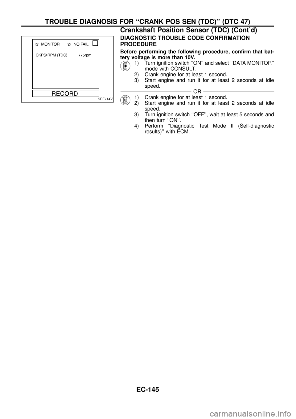
1) Turn ignition switch ``ON'' and select ``DATA MONITOR''
mode with CONSULT.
2) Crank engine for at least 1 second.
3) Start engine and run it for at least 2 seconds at idle
speed.
-------------------------------------------------------------------------------------------------------------------------------------------------------------------------------------------------------------------------------------------------------OR-------------------------------------------------------------------------------------------------------------------------------------------------------------------------------------------------------------------------------------------------------
1) Crank engine for at least 1 second.
2) Start engine and run it for at least 2 seconds at idle
speed.
3) Turn ignition switch ``OFF'', wait at least 5 seconds and
then turn ``ON''.
4) Perform ``Diagnostic Test Mode II (Self-diagnostic
results)'' with ECM.SEF714V
TROUBLE DIAGNOSIS FOR ``CRANK POS SEN (TDC)'' (DTC 47)
Crankshaft Position Sensor (TDC) (Cont'd)
EC-145
Page 148 of 192
TEC437
TROUBLE DIAGNOSIS FOR ``CRANK POS SEN (TDC)'' (DTC 47)
Crankshaft Position Sensor (TDC) (Cont'd)
EC-146
Page 149 of 192
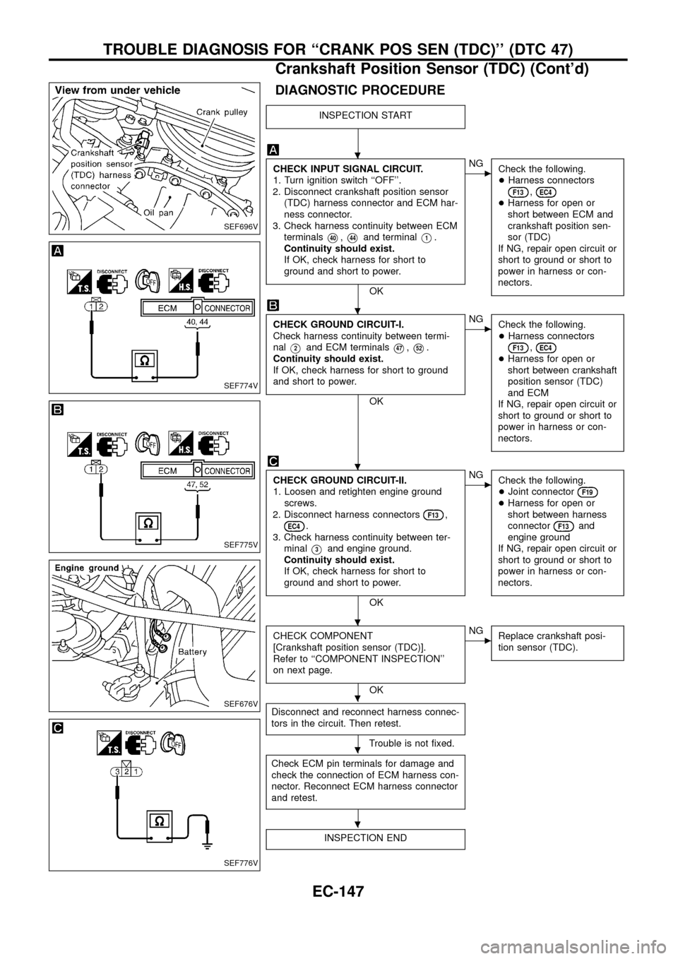
DIAGNOSTIC PROCEDURE
INSPECTION START
CHECK INPUT SIGNAL CIRCUIT.
1. Turn ignition switch ``OFF''.
2. Disconnect crankshaft position sensor
(TDC) harness connector and ECM har-
ness connector.
3. Check harness continuity between ECM
terminals
V40,V44and terminalV1.
Continuity should exist.
If OK, check harness for short to
ground and short to power.
OK
cNG
Check the following.
+Harness connectors
F13,EC4+Harness for open or
short between ECM and
crankshaft position sen-
sor (TDC)
If NG, repair open circuit or
short to ground or short to
power in harness or con-
nectors.
CHECK GROUND CIRCUIT-I.
Check harness continuity between termi-
nal
V2and ECM terminalsV47,V52.
Continuity should exist.
If OK, check harness for short to ground
and short to power.
OK
cNG
Check the following.
+Harness connectors
F13,EC4+Harness for open or
short between crankshaft
position sensor (TDC)
and ECM
If NG, repair open circuit or
short to ground or short to
power in harness or con-
nectors.
CHECK GROUND CIRCUIT-II.
1. Loosen and retighten engine ground
screws.
2. Disconnect harness connectors
F13,EC4.
3. Check harness continuity between ter-
minal
V3and engine ground.
Continuity should exist.
If OK, check harness for short to
ground and short to power.
OK
cNG
Check the following.
+Joint connector
F19+Harness for open or
short between harness
connector
F13and
engine ground
If NG, repair open circuit or
short to ground or short to
power in harness or con-
nectors.
CHECK COMPONENT
[Crankshaft position sensor (TDC)].
Refer to ``COMPONENT INSPECTION''
on next page.
OK
cNG
Replace crankshaft posi-
tion sensor (TDC).
Disconnect and reconnect harness connec-
tors in the circuit. Then retest.
Trouble is not ®xed.
Check ECM pin terminals for damage and
check the connection of ECM harness con-
nector. Reconnect ECM harness connector
and retest.
INSPECTION END
SEF696V
SEF774V
SEF775V
SEF676V
SEF776V
.
.
.
.
.
.
.
TROUBLE DIAGNOSIS FOR ``CRANK POS SEN (TDC)'' (DTC 47)
Crankshaft Position Sensor (TDC) (Cont'd)
EC-147
Page 150 of 192
COMPONENT INSPECTION
Crankshaft position sensor (TDC)
1. Disconnect crankshaft position sensor (TDC) harness connec-
tor.
2. Loosen the ®xing bolt of the sensor.
3. Remove the sensor.
4. Visually check the sensor for chipping.
5. Check resistance between terminals
V1andV2.
Resistance: Approximately 0.8 - 1.2 kW
[at 25ÉC (77ÉF)]
If NG, replace crankshaft position sensor (TDC).
SEF620S
SEF697V
TROUBLE DIAGNOSIS FOR ``CRANK POS SEN (TDC)'' (DTC 47)
Crankshaft Position Sensor (TDC) (Cont'd)
EC-148
Page 153 of 192
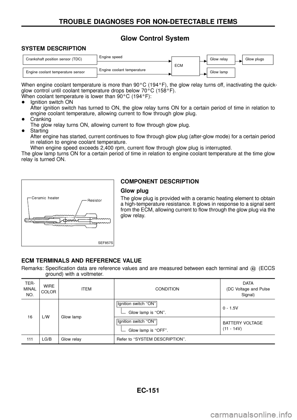
Glow Control System
SYSTEM DESCRIPTION
Crankshaft position sensor (TDC)cEngine speed
ECMcGlow relaycGlow plugs
Engine coolant temperature sensorcEngine coolant temperaturecGlow lamp
When engine coolant temperature is more than 90ÉC (194ÉF), the glow relay turns off, inactivating the quick-
glow control until coolant temperature drops below 70ÉC (158ÉF).
When coolant temperature is lower than 90ÉC (194ÉF):
+Ignition switch ON
After ignition switch has turned to ON, the glow relay turns ON for a certain period of time in relation to
engine coolant temperature, allowing current to ¯ow through glow plug.
+Cranking
The glow relay turns ON, allowing current to ¯ow through glow plug.
+Starting
After engine has started, current continues to ¯ow through glow plug (after-glow mode) for a certain period
in relation to engine coolant temperature.
When engine speed exceeds 2,400 rpm, current ¯ow through glow plug is interrupted.
The glow lamp turns ON for a certain period of time in relation to engine coolant temperature at the time glow
relay is turned ON.
COMPONENT DESCRIPTION
Glow plug
The glow plug is provided with a ceramic heating element to obtain
a high-temperature resistance. It glows in response to a signal sent
from the ECM, allowing current to ¯ow through the glow plug via the
glow relay.
ECM TERMINALS AND REFERENCE VALUE
Remarks: Speci®cation data are reference values and are measured between each terminal andV43(ECCS
ground) with a voltmeter.
TER-
MINAL
NO.WIRE
COLORITEM CONDITIONDATA
(DC Voltage and Pulse
Signal)
16 L/W Glow lampIgnition switch ``ON''
Glow lamp is ``ON''.0 - 1.5V
Ignition switch ``ON''
Glow lamp is ``OFF''.BATTERY VOLTAGE
(11 - 14V)
111 LG/B Glow relay Refer to ``SYSTEM DESCRIPTION''.
SEF857S
TROUBLE DIAGNOSES FOR NON-DETECTABLE ITEMS
EC-151