1998 NISSAN PATROL relay
[x] Cancel search: relayPage 64 of 192
TER-
MINAL
NO.WIRE
COLORITEM CONDITIONDATA
(DC Voltage and Pulse
Signal)
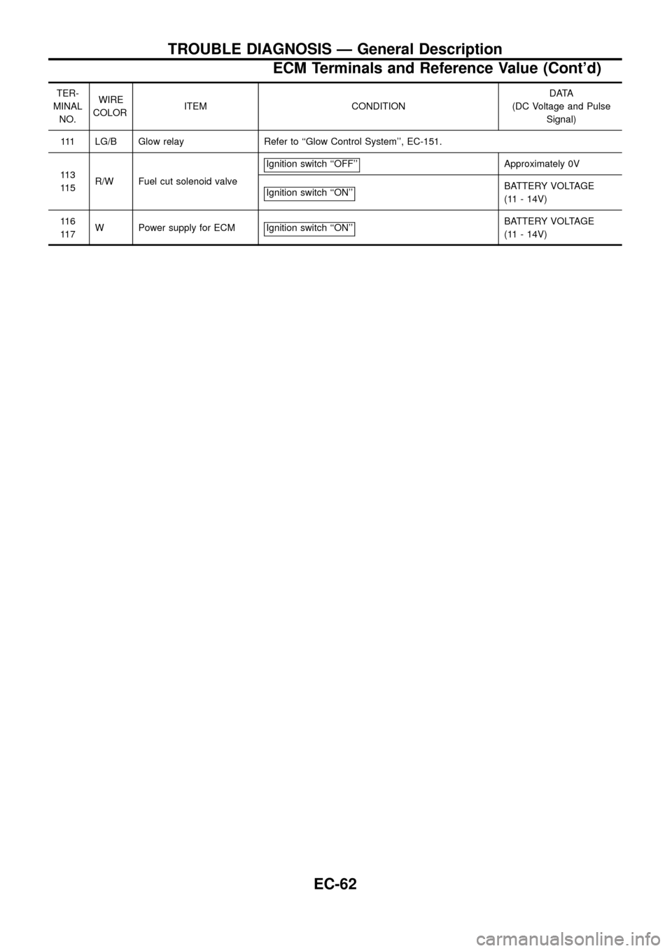
111 LG/B Glow relay Refer to ``Glow Control System'', EC-151.
11 3
11 5R/W Fuel cut solenoid valveIgnition switch ``OFF''
Approximately 0V
Ignition switch ``ON''
BATTERY VOLTAGE
(11 - 14V)
11 6
11 7W Power supply for ECM Ignition switch ``ON''
BATTERY VOLTAGE
(11 - 14V)
TROUBLE DIAGNOSIS Ð General Description
ECM Terminals and Reference Value (Cont'd)
EC-62
Page 65 of 192
Main Power Supply and Ground Circuit
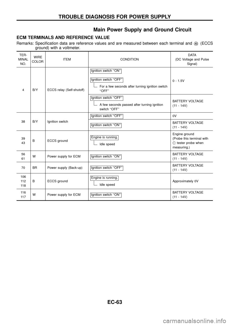
ECM TERMINALS AND REFERENCE VALUE
Remarks: Speci®cation data are reference values and are measured between each terminal andV43(ECCS
ground) with a voltmeter.
TER-
MINAL
NO.WIRE
COLORITEM CONDITIONDATA
(DC Voltage and Pulse
Signal)
4 B/Y ECCS relay (Self-shutoff)Ignition switch ``ON''
Ignition switch ``OFF''
For a few seconds after turning ignition switch
``OFF''0 - 1.5V
Ignition switch ``OFF''
A few seconds passed after turning ignition
switch ``OFF''BATTERY VOLTAGE
(11 - 14V)
38 B/Y Ignition switchIgnition switch ``OFF''
0V
Ignition switch ``ON''
BATTERY VOLTAGE
(11 - 14V)
39
43B ECCS groundEngine is running.
Idle speedEngine ground
(Probe this terminal with
@tester probe when
measuring.)
56
61W Power supply for ECM Ignition switch ``ON''
BATTERY VOLTAGE
(11 - 14V)
70 BR Power supply (Back-up) Ignition switch ``OFF''
BATTERY VOLTAGE
(11 - 14V)
106
11 2
11 8B ECCS groundEngine is running.
Idle speedApproximately 0V
11 6
11 7W Power supply for ECM Ignition switch ``ON''
BATTERY VOLTAGE
(11 - 14V)
TROUBLE DIAGNOSIS FOR POWER SUPPLY
EC-63
Page 68 of 192
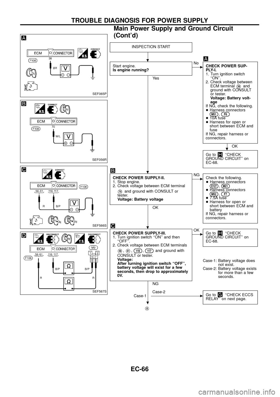
INSPECTION START
Start engine.
Is engine running?
Ye s
cNo
CHECK POWER SUP-
PLY-I.
1. Turn ignition switch
``ON''.
2. Check voltage between
ECM terminal
V38and
ground with CONSULT
or tester.
Voltage: Battery volt-
age
If NG, check the following.
+Harness connectors
M51,F6+10A fuse
+Harness for open or
short between ECM and
fuse
If NG, repair harness or
connectors.
OK
Go to
``CHECK
GROUND CIRCUIT'' on
EC-68.
CHECK POWER SUPPLY-II.
1. Stop engine.
2. Check voltage between ECM terminal
V70and ground with CONSULT or
tester.
Voltage: Battery voltage
OK
cNG
Check the following.
+Harness connectors
E127,M21+Harness connectorsM52,F7+7.5A fuse
+Harness for open or
short between ECM and
battery
If NG, repair harness or
connectors.
CHECK POWER SUPPLY-III.
1. Turn ignition switch ``ON'' and then
``OFF''.
2. Check voltage between ECM terminals
V56,V61,11 6,11 7and ground with
CONSULT or tester.
Voltage:
After turning ignition switch ``OFF'',
battery voltage will exist for a few
seconds, then drop to approximately
0V.
NG
cOK
Go to``CHECK
GROUND CIRCUIT'' on
EC-68.
Case-1: Battery voltage does
not exist.
Case-2: Battery voltage exists
for more than a few
seconds.
Case-1
cCase-2
Go to``CHECK ECCS
RELAY'' on next page.
jA
SEF065P
SEF056R
SEF566S
SEF567S
.
.
.
.
.
TROUBLE DIAGNOSIS FOR POWER SUPPLY
Main Power Supply and Ground Circuit
(Cont'd)
EC-66
Page 69 of 192
jA
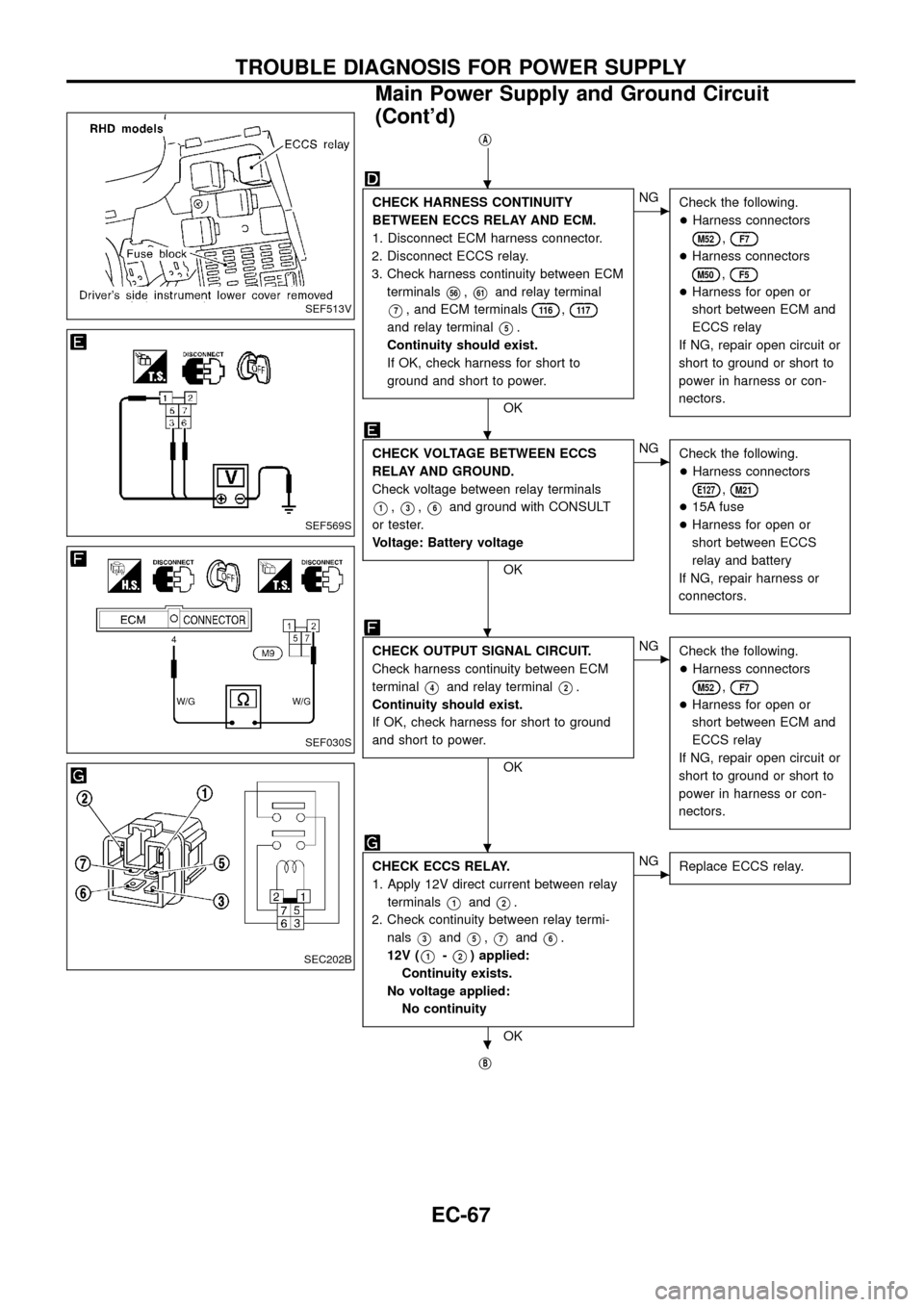
CHECK HARNESS CONTINUITY
BETWEEN ECCS RELAY AND ECM.
1. Disconnect ECM harness connector.
2. Disconnect ECCS relay.
3. Check harness continuity between ECM
terminals
V56,V61and relay terminal
V7, and ECM terminals11 6,11 7
and relay terminalV5.
Continuity should exist.
If OK, check harness for short to
ground and short to power.
OK
cNG
Check the following.
+Harness connectors
M52,F7
+Harness connectors
M50,F5
+Harness for open or
short between ECM and
ECCS relay
If NG, repair open circuit or
short to ground or short to
power in harness or con-
nectors.
CHECK VOLTAGE BETWEEN ECCS
RELAY AND GROUND.
Check voltage between relay terminals
V1,V3,V6and ground with CONSULT
or tester.
Voltage: Battery voltage
OK
cNG
Check the following.
+Harness connectors
E127,M21
+15A fuse
+Harness for open or
short between ECCS
relay and battery
If NG, repair harness or
connectors.
CHECK OUTPUT SIGNAL CIRCUIT.
Check harness continuity between ECM
terminal
V4and relay terminalV2.
Continuity should exist.
If OK, check harness for short to ground
and short to power.
OK
cNG
Check the following.
+Harness connectors
M52,F7
+Harness for open or
short between ECM and
ECCS relay
If NG, repair open circuit or
short to ground or short to
power in harness or con-
nectors.
CHECK ECCS RELAY.
1. Apply 12V direct current between relay
terminals
V1andV2.
2. Check continuity between relay termi-
nals
V3andV5,V7andV6.
12V (
V1-V2) applied:
Continuity exists.
No voltage applied:
No continuity
OK
cNG
Replace ECCS relay.
jB
SEF513V
SEF569S
SEF030S
SEC202B
.
.
.
.
.
TROUBLE DIAGNOSIS FOR POWER SUPPLY
Main Power Supply and Ground Circuit
(Cont'd)
EC-67
Page 79 of 192
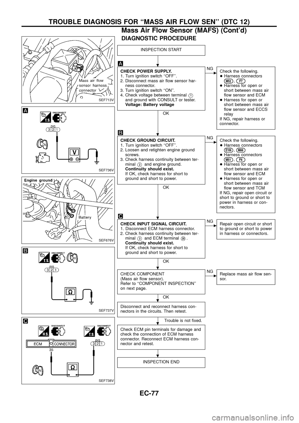
DIAGNOSTIC PROCEDURE
INSPECTION START
CHECK POWER SUPPLY.
1. Turn ignition switch ``OFF''.
2. Disconnect mass air ¯ow sensor har-
ness connector.
3. Turn ignition switch ``ON''.
4. Check voltage between terminal
V1and ground with CONSULT or tester.
Voltage: Battery voltage
OK
cNG
Check the following.
+Harness connectors
M52,F7+Harness for open or
short between mass air
¯ow sensor and ECM
+Harness for open or
short between mass air
¯ow sensor and ECCS
relay
If NG, repair harness or
connector.
CHECK GROUND CIRCUIT.
1. Turn ignition switch ``OFF''.
2. Loosen and retighten engine ground
screws.
3. Check harness continuity between ter-
minal
V2and engine ground.
Continuity should exist.
If OK, check harness for short to
ground and short to power.
OK
cNG
Check the following.
+Harness connectors
E106,M88+Harness connectorsM51,F6+Harness for open or
short between mass air
¯ow sensor and ECM
+Harness for open or
short between mass air
¯ow sensor and TCM
If NG, repair open circuit or
short to ground or short to
power in harness or con-
nectors.
CHECK INPUT SIGNAL CIRCUIT.
1. Disconnect ECM harness connector.
2. Check harness continuity between ter-
minal
V3and ECM terminalV35.
Continuity should exist.
If OK, check harness for short to
ground and short to power.
OK
cNG
Repair open circuit or short
to ground or short to power
in harness or connectors.
CHECK COMPONENT
(Mass air ¯ow sensor).
Refer to ``COMPONENT INSPECTION''
on next page.
OK
cNG
Replace mass air ¯ow sen-
sor.
Disconnect and reconnect harness con-
nectors in the circuits. Then retest.
Trouble is not ®xed.
Check ECM pin terminals for damage and
check the connection of ECM harness
connector. Reconnect ECM harness con-
nector and retest.
INSPECTION END
SEF713V
SEF736V
SEF676V
SEF737V
SEF738V
.
.
.
.
.
.
.
TROUBLE DIAGNOSIS FOR ``MASS AIR FLOW SEN'' (DTC 12)
Mass Air Flow Sensor (MAFS) (Cont'd)
EC-77
Page 98 of 192
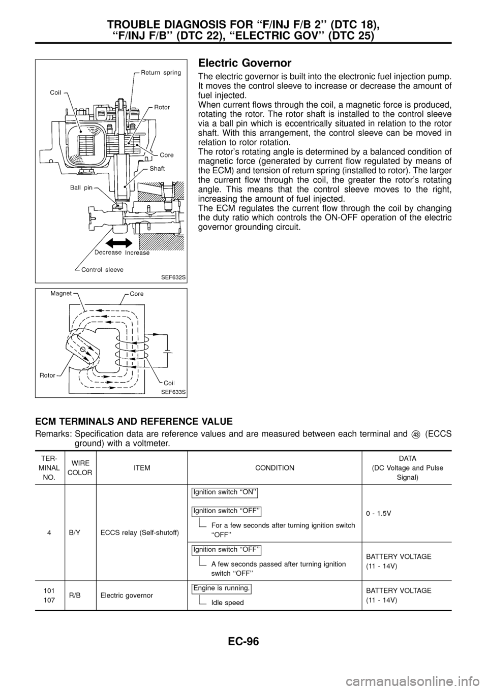
Electric Governor
The electric governor is built into the electronic fuel injection pump.
It moves the control sleeve to increase or decrease the amount of
fuel injected.
When current ¯ows through the coil, a magnetic force is produced,
rotating the rotor. The rotor shaft is installed to the control sleeve
via a ball pin which is eccentrically situated in relation to the rotor
shaft. With this arrangement, the control sleeve can be moved in
relation to rotor rotation.
The rotor's rotating angle is determined by a balanced condition of
magnetic force (generated by current ¯ow regulated by means of
the ECM) and tension of return spring (installed to rotor). The larger
the current ¯ow through the coil, the greater the rotor's rotating
angle. This means that the control sleeve moves to the right,
increasing the amount of fuel injected.
The ECM regulates the current ¯ow through the coil by changing
the duty ratio which controls the ON-OFF operation of the electric
governor grounding circuit.
ECM TERMINALS AND REFERENCE VALUE
Remarks: Speci®cation data are reference values and are measured between each terminal andV43(ECCS
ground) with a voltmeter.
TER-
MINAL
NO.WIRE
COLORITEM CONDITIONDATA
(DC Voltage and Pulse
Signal)
4 B/Y ECCS relay (Self-shutoff)Ignition switch ``ON''
Ignition switch ``OFF''
For a few seconds after turning ignition switch
``OFF''0 - 1.5V
Ignition switch ``OFF''
A few seconds passed after turning ignition
switch ``OFF''BATTERY VOLTAGE
(11 - 14V)
101
107R/B Electric governorEngine is running.
Idle speedBATTERY VOLTAGE
(11 - 14V)
SEF632S
SEF633S
TROUBLE DIAGNOSIS FOR ``F/INJ F/B 2'' (DTC 18),
``F/INJ F/B'' (DTC 22), ``ELECTRIC GOV'' (DTC 25)
EC-96
Page 115 of 192
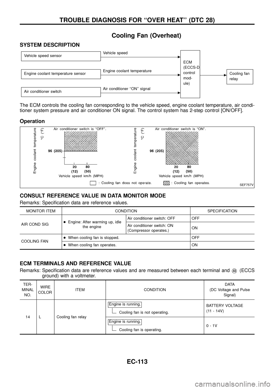
Cooling Fan (Overheat)
SYSTEM DESCRIPTION
Vehicle speed sensorcVehicle speed
ECM
(ECCS-D
control
mod-
ule)
cCooling fan
relayEngine coolant temperature sensorcEngine coolant temperature
Air conditioner switch
cAir conditioner ``ON'' signal
The ECM controls the cooling fan corresponding to the vehicle speed, engine coolant temperature, air condi-
tioner system pressure and air conditioner ON signal. The control system has 2-step control [ON/OFF].
Operation
CONSULT REFERENCE VALUE IN DATA MONITOR MODE
Remarks: Speci®cation data are reference values.
MONITOR ITEM CONDITION SPECIFICATION
AIR COND SIG+Engine: After warming up, idle
the engineAir conditioner switch: OFF OFF
Air conditioner switch: ON
(Compressor operates.)ON
COOLING FAN+When cooling fan is stopped. OFF
+When cooling fan operates. ON
ECM TERMINALS AND REFERENCE VALUE
Remarks: Speci®cation data are reference values and are measured between each terminal andV43(ECCS
ground) with a voltmeter.
TER-
MINAL
NO.WIRE
COLORITEM CONDITIONDATA
(DC Voltage and Pulse
Signal)
14 L Cooling fan relayEngine is running.
Cooling fan is not operating.BATTERY VOLTAGE
(11 - 14V)
Engine is running.
Cooling fan is operating.0-1V
SEF757V
TROUBLE DIAGNOSIS FOR ``OVER HEAT'' (DTC 28)
EC-113
Page 116 of 192
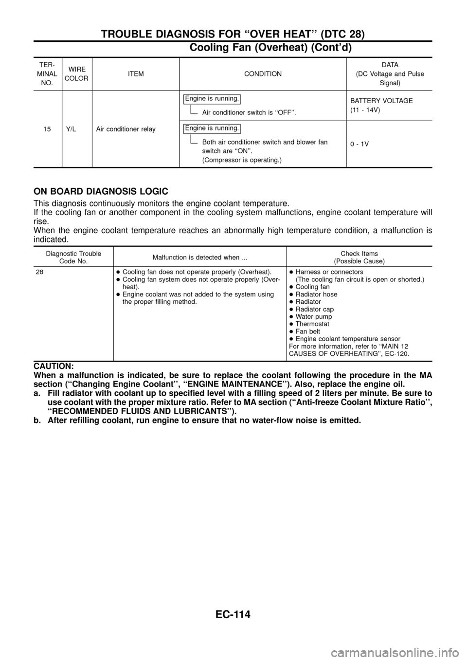
TER-
MINAL
NO.WIRE
COLORITEM CONDITIONDATA
(DC Voltage and Pulse
Signal)
15 Y/L Air conditioner relayEngine is running.
Air conditioner switch is ``OFF''.BATTERY VOLTAGE
(11 - 14V)
Engine is running.
Both air conditioner switch and blower fan
switch are ``ON''.
(Compressor is operating.)0-1V
ON BOARD DIAGNOSIS LOGIC
This diagnosis continuously monitors the engine coolant temperature.
If the cooling fan or another component in the cooling system malfunctions, engine coolant temperature will
rise.
When the engine coolant temperature reaches an abnormally high temperature condition, a malfunction is
indicated.
Diagnostic Trouble
Code No.Malfunction is detected when ...Check Items
(Possible Cause)
28+Cooling fan does not operate properly (Overheat).
+Cooling fan system does not operate properly (Over-
heat).
+Engine coolant was not added to the system using
the proper ®lling method.+Harness or connectors
(The cooling fan circuit is open or shorted.)
+Cooling fan
+Radiator hose
+Radiator
+Radiator cap
+Water pump
+Thermostat
+Fan belt
+Engine coolant temperature sensor
For more information, refer to ``MAIN 12
CAUSES OF OVERHEATING'', EC-120.
CAUTION:
When a malfunction is indicated, be sure to replace the coolant following the procedure in the MA
section (``Changing Engine Coolant'', ``ENGINE MAINTENANCE''). Also, replace the engine oil.
a. Fill radiator with coolant up to speci®ed level with a ®lling speed of 2 liters per minute. Be sure to
use coolant with the proper mixture ratio. Refer to MA section (``Anti-freeze Coolant Mixture Ratio'',
``RECOMMENDED FLUIDS AND LUBRICANTS'').
b. After re®lling coolant, run engine to ensure that no water-¯ow noise is emitted.
TROUBLE DIAGNOSIS FOR ``OVER HEAT'' (DTC 28)
Cooling Fan (Overheat) (Cont'd)
EC-114