Page 18 of 192
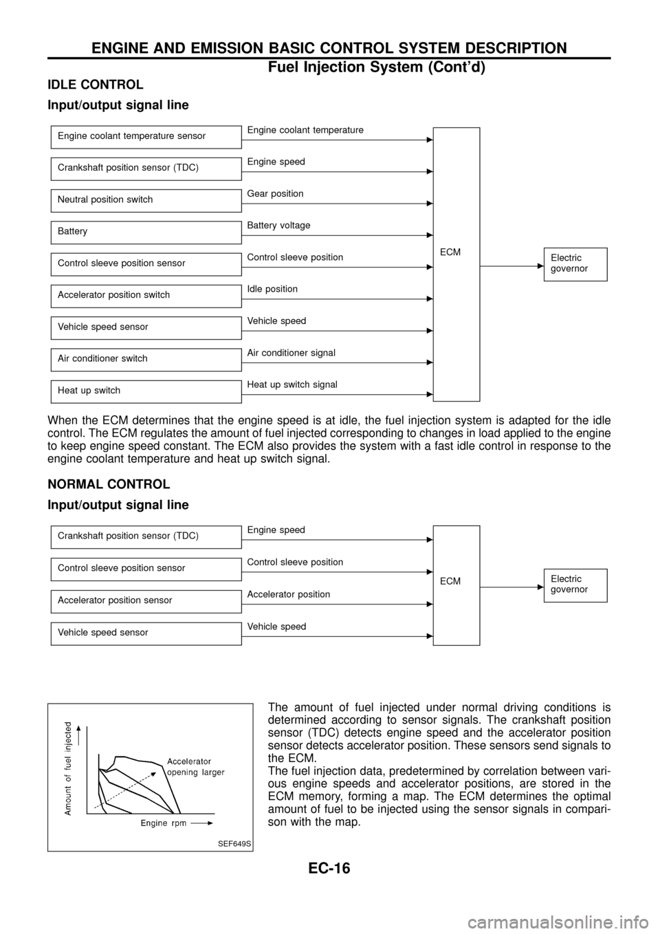
IDLE CONTROL
Input/output signal line
Engine coolant temperature sensorcEngine coolant temperature
ECM
cElectric
governor
Crankshaft position sensor (TDC)cEngine speed
Neutral position switch
cGear position
Battery
cBattery voltage
Control sleeve position sensor
cControl sleeve position
Accelerator position switch
cIdle position
Vehicle speed sensor
cVehicle speed
Air conditioner switch
cAir conditioner signal
Heat up switch
cHeat up switch signal
When the ECM determines that the engine speed is at idle, the fuel injection system is adapted for the idle
control. The ECM regulates the amount of fuel injected corresponding to changes in load applied to the engine
to keep engine speed constant. The ECM also provides the system with a fast idle control in response to the
engine coolant temperature and heat up switch signal.
NORMAL CONTROL
Input/output signal line
Crankshaft position sensor (TDC)cEngine speed
ECM
cElectric
governorControl sleeve position sensorcControl sleeve position
Accelerator position sensor
cAccelerator position
Vehicle speed sensor
cVehicle speed
The amount of fuel injected under normal driving conditions is
determined according to sensor signals. The crankshaft position
sensor (TDC) detects engine speed and the accelerator position
sensor detects accelerator position. These sensors send signals to
the ECM.
The fuel injection data, predetermined by correlation between vari-
ous engine speeds and accelerator positions, are stored in the
ECM memory, forming a map. The ECM determines the optimal
amount of fuel to be injected using the sensor signals in compari-
son with the map.
SEF649S
ENGINE AND EMISSION BASIC CONTROL SYSTEM DESCRIPTION
Fuel Injection System (Cont'd)
EC-16
Page 19 of 192
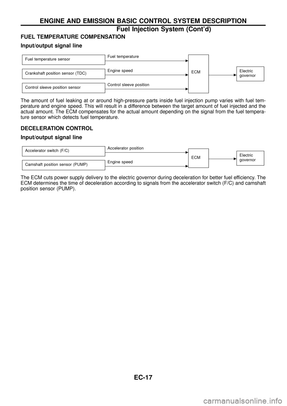
FUEL TEMPERATURE COMPENSATION
Input/output signal line
Fuel temperature sensorcFuel temperature
ECM
cElectric
governorCrankshaft position sensor (TDC)cEngine speed
Control sleeve position sensor
cControl sleeve position
The amount of fuel leaking at or around high-pressure parts inside fuel injection pump varies with fuel tem-
perature and engine speed. This will result in a difference between the target amount of fuel injected and the
actual amount. The ECM compensates for the actual amount depending on the signal from the fuel tempera-
ture sensor which detects fuel temperature.
DECELERATION CONTROL
Input/output signal line
Accelerator switch (F/C)cAccelerator position
ECM
cElectric
governor
Camshaft position sensor (PUMP)cEngine speed
The ECM cuts power supply delivery to the electric governor during deceleration for better fuel efficiency. The
ECM determines the time of deceleration according to signals from the accelerator switch (F/C) and camshaft
position sensor (PUMP).
ENGINE AND EMISSION BASIC CONTROL SYSTEM DESCRIPTION
Fuel Injection System (Cont'd)
EC-17
Page 20 of 192
Fuel Injection Timing System
SYSTEM DESCRIPTION
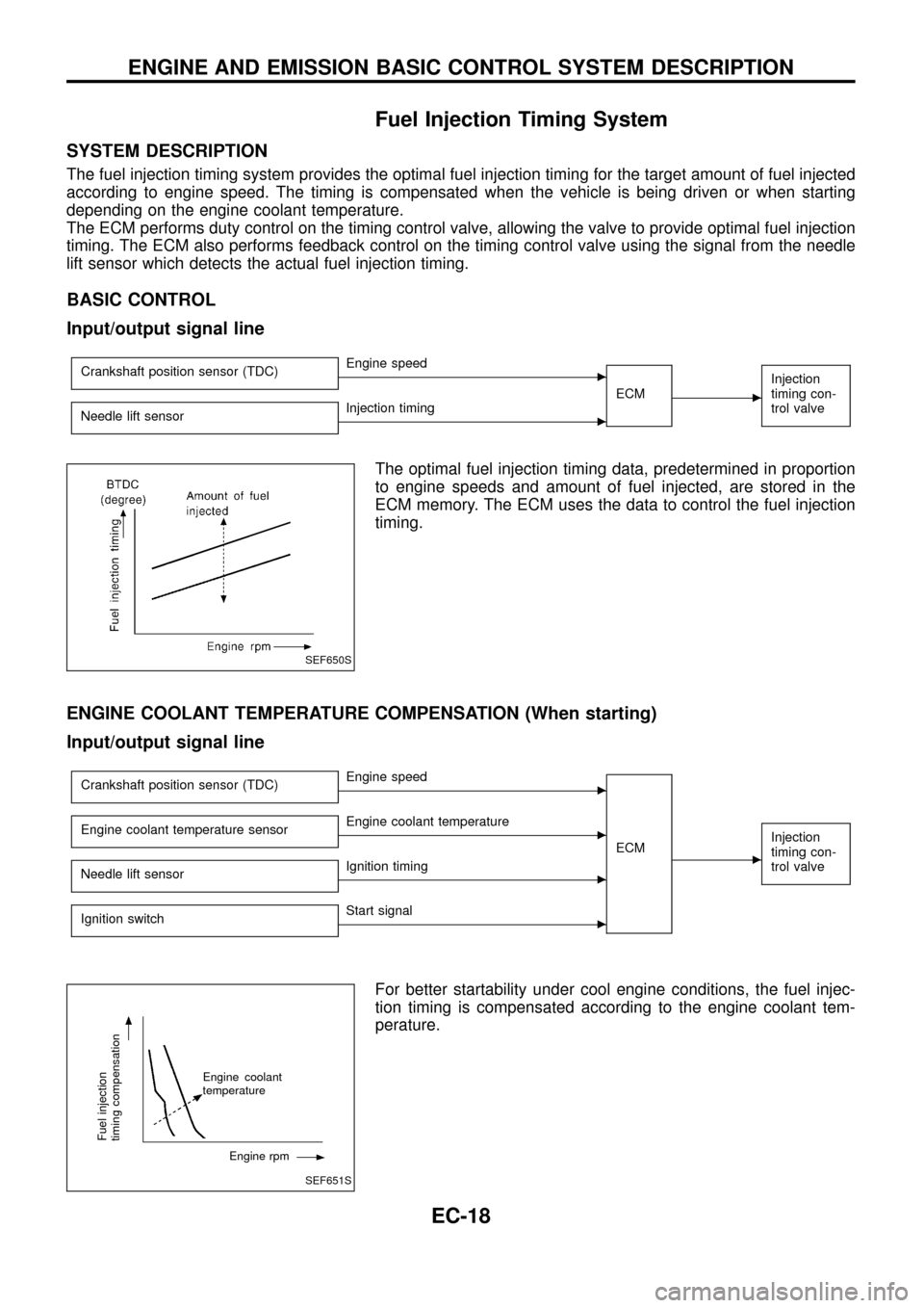
The fuel injection timing system provides the optimal fuel injection timing for the target amount of fuel injected
according to engine speed. The timing is compensated when the vehicle is being driven or when starting
depending on the engine coolant temperature.
The ECM performs duty control on the timing control valve, allowing the valve to provide optimal fuel injection
timing. The ECM also performs feedback control on the timing control valve using the signal from the needle
lift sensor which detects the actual fuel injection timing.
BASIC CONTROL
Input/output signal line
Crankshaft position sensor (TDC)cEngine speed
ECM
c
Injection
timing con-
trol valve
Needle lift sensorcInjection timing
The optimal fuel injection timing data, predetermined in proportion
to engine speeds and amount of fuel injected, are stored in the
ECM memory. The ECM uses the data to control the fuel injection
timing.
ENGINE COOLANT TEMPERATURE COMPENSATION (When starting)
Input/output signal line
Crankshaft position sensor (TDC)cEngine speed
ECM
c
Injection
timing con-
trol valveEngine coolant temperature sensorcEngine coolant temperature
Needle lift sensor
cIgnition timing
Ignition switch
cStart signal
For better startability under cool engine conditions, the fuel injec-
tion timing is compensated according to the engine coolant tem-
perature.
SEF650S
SEF651S
Fuel injection
timing compensation
Engine coolant
temperature
Engine rpm
ENGINE AND EMISSION BASIC CONTROL SYSTEM DESCRIPTION
EC-18
Page 21 of 192
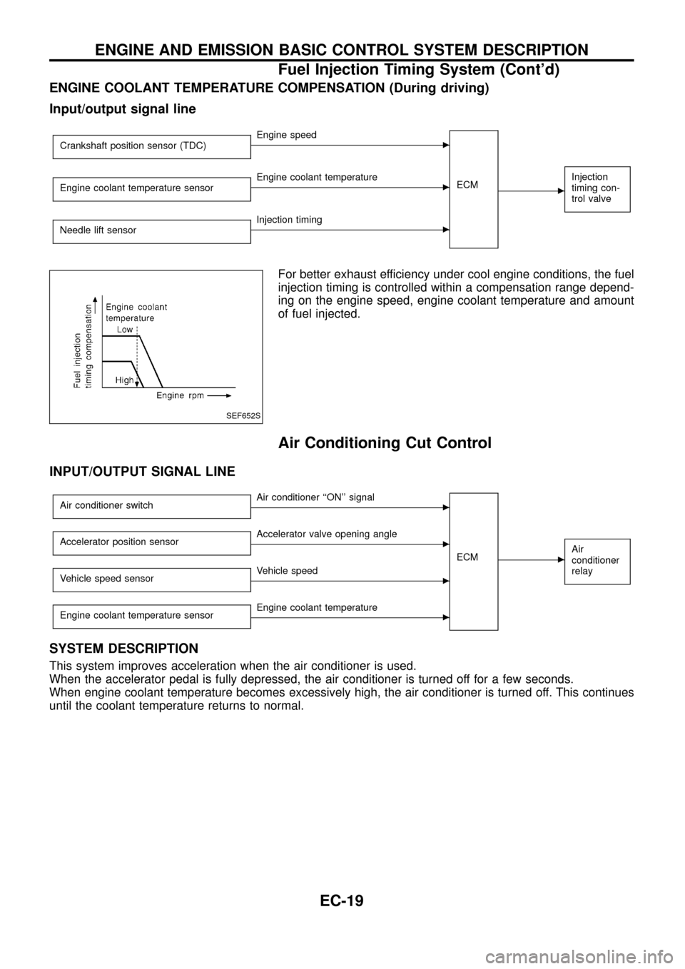
ENGINE COOLANT TEMPERATURE COMPENSATION (During driving)
Input/output signal line
Crankshaft position sensor (TDC)cEngine speed
ECM
c
Injection
timing con-
trol valveEngine coolant temperature sensorcEngine coolant temperature
Needle lift sensor
cInjection timing
For better exhaust efficiency under cool engine conditions, the fuel
injection timing is controlled within a compensation range depend-
ing on the engine speed, engine coolant temperature and amount
of fuel injected.
Air Conditioning Cut Control
INPUT/OUTPUT SIGNAL LINE
Air conditioner switchcAir conditioner ``ON'' signal
ECM
cAir
conditioner
relayAccelerator position sensorcAccelerator valve opening angle
Vehicle speed sensor
cVehicle speed
Engine coolant temperature sensor
cEngine coolant temperature
SYSTEM DESCRIPTION
This system improves acceleration when the air conditioner is used.
When the accelerator pedal is fully depressed, the air conditioner is turned off for a few seconds.
When engine coolant temperature becomes excessively high, the air conditioner is turned off. This continues
until the coolant temperature returns to normal.
SEF652S
ENGINE AND EMISSION BASIC CONTROL SYSTEM DESCRIPTION
Fuel Injection Timing System (Cont'd)
EC-19
Page 22 of 192
Fuel Cut Control (at no load & high engine
speed)
INPUT/OUTPUT SIGNAL LINE
Vehicle speed sensorcVehicle speed
ECM
cElectric
governor
Neutral position switchcNeutral position
Accelerator position switch or Accelerator
switch (F/C)
cAccelerator position
Engine coolant temperature sensor
cEngine coolant temperature
Crankshaft position sensor (TDC)
cEngine speed
If the engine speed is above 3,000 rpm with no load (for example,
in neutral and engine speed over 3,000 rpm) fuel will be cut off after
some time. The exact time when the fuel is cut off varies based on
engine speed.
Fuel cut will operate until the engine speed reaches 1,500 rpm,
then fuel cut is cancelled.
NOTE:
This function is different from deceleration control and fuel cut
solenoid valve control listed under ``Fuel Injection System'',
EC-15 and ``TROUBLE DIAGNOSIS FOR DTC 36, 37, 38'',
EC-130.
ENGINE AND EMISSION BASIC CONTROL SYSTEM DESCRIPTION
EC-20
Page 24 of 192
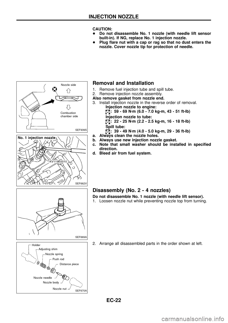
CAUTION:
+Do not disassemble No. 1 nozzle (with needle lift sensor
built-in). If NG, replace No. 1 injection nozzle.
+Plug ¯are nut with a cap or rag so that no dust enters the
nozzle. Cover nozzle tip for protection of needle.
Removal and Installation
1. Remove fuel injection tube and spill tube.
2. Remove injection nozzle assembly.
Also remove gasket from nozzle end.
3. Install injection nozzle in the reverse order of removal.
Injection nozzle to engine:
: 59-69Nzm (6.0 - 7.0 kg-m, 43 - 51 ft-lb)
Injection nozzle to tube:
: 22-25Nzm (2.2 - 2.5 kg-m, 16 - 18 ft-lb)
Spill tube:
: 39-49Nzm (4.0 - 5.0 kg-m, 29 - 36 ft-lb)
a. Always clean the nozzle holes.
b. Always use new injection nozzle gasket.
c. Note that small washer should be installed in speci®ed
direction.
d. Bleed air from fuel system.
Disassembly (No.2-4nozzles)
Do not disassemble No. 1 nozzle (with needle lift sensor).
1. Loosen nozzle nut while preventing nozzle top from turning.
2. Arrange all disassembled parts in the order shown at left.
SEF939S
Nozzle side
Combustion
chamber side
SEF662V
SEF669A
SEF670A
Holder
Adjusting shim
Nozzle spring
Push rod
Distance piece
Nozzle nut Nozzle body Nozzle needle
INJECTION NOZZLE
EC-22
Page 25 of 192
Inspection (No.2-4nozzles)
Thoroughly clean all disassembled parts with fresh kerosene or
solvent.
+If nozzle needle is damaged or fused, replace nozzle assem-
bly with a new one.
+If end of nozzle needle is seized or excessively discolored,
replace nozzle assembly.
+Check nozzle body and distance piece for proper contact. If
excessively worn or damaged, replace nozzle assembly or dis-
tance piece.
+Check distance piece and nozzle holder for proper contact. If
excessively worn or damaged, replace distance piece or nozzle
holder.
+Check nozzle spring for excessive wear or damage. If exces-
sively worn or damaged, replace it with a new spring.
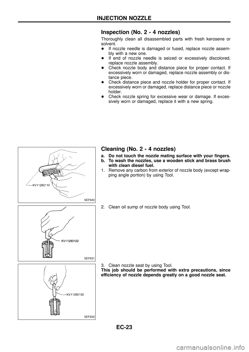
Cleaning (No.2-4nozzles)
a. Do not touch the nozzle mating surface with your ®ngers.
b. To wash the nozzles, use a wooden stick and brass brush
with clean diesel fuel.
1. Remove any carbon from exterior of nozzle body (except wrap-
ping angle portion) by using Tool.
2. Clean oil sump of nozzle body using Tool.
3. Clean nozzle seat by using Tool.
This job should be performed with extra precautions, since
efficiency of nozzle depends greatly on a good nozzle seat.
SEF830
SEF831
SEF832
INJECTION NOZZLE
EC-23
Page 27 of 192
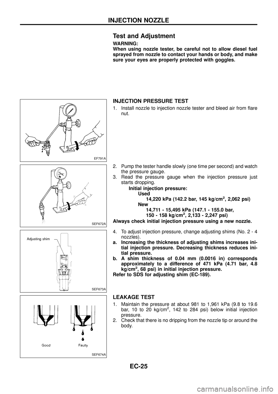
Test and Adjustment
WARNING:
When using nozzle tester, be careful not to allow diesel fuel
sprayed from nozzle to contact your hands or body, and make
sure your eyes are properly protected with goggles.
INJECTION PRESSURE TEST
1. Install nozzle to injection nozzle tester and bleed air from ¯are
nut.
2. Pump the tester handle slowly (one time per second) and watch
the pressure gauge.
3. Read the pressure gauge when the injection pressure just
starts dropping.
Initial injection pressure:
Used
14,220 kPa (142.2 bar, 145 kg/cm
2, 2,062 psi)
New
14,711 - 15,495 kPa (147.1 - 155.0 bar,
150 - 158 kg/cm
2, 2,133 - 2,247 psi)
Always check initial injection pressure using a new nozzle.
4. To adjust injection pressure, change adjusting shims (No. 2 - 4
nozzles).
a. Increasing the thickness of adjusting shims increases ini-
tial injection pressure. Decreasing thickness reduces ini-
tial pressure.
b. A shim thickness of 0.04 mm (0.0016 in) corresponds
approximately to a difference of 471 kPa (4.71 bar, 4.8
kg/cm
2, 68 psi) in initial injection pressure.
Refer to SDS for adjusting shim (EC-189).
LEAKAGE TEST
1. Maintain the pressure at about 981 to 1,961 kPa (9.8 to 19.6
bar, 10 to 20 kg/cm2, 142 to 284 psi) below initial injection
pressure.
2. Check that there is no dripping from the nozzle tip or around the
body.
EF791A
SEF672A
SEF673A
Adjusting shim
SEF674A
INJECTION NOZZLE
EC-25