Page 61 of 192
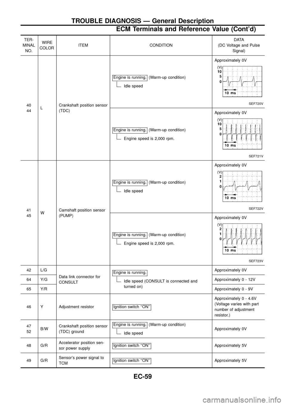
TER-
MINAL
NO.WIRE
COLORITEM CONDITIONDATA
(DC Voltage and Pulse
Signal)
40
44LCrankshaft position sensor
(TDC)Engine is running.
(Warm-up condition)
Idle speedApproximately 0V
SEF720V
Engine is running.(Warm-up condition)
Engine speed is 2,000 rpm.Approximately 0V
SEF721V
41
45WCamshaft position sensor
(PUMP)Engine is running.
(Warm-up condition)
Idle speedApproximately 0V
SEF722V
Engine is running.(Warm-up condition)
Engine speed is 2,000 rpm.Approximately 0V
SEF723V
42 L/G
Data link connector for
CONSULTEngine is running.
Idle speed (CONSULT is connected and
turned on)Approximately 0V
64 Y/GApproximately0-12V
65 Y/RApproximately0-9V
46 Y Adjustment resistor Ignition switch ``ON''
Approximately 0 - 4.6V
(Voltage varies with part
number of adjustment
resistor.)
47
52B/WCrankshaft position sensor
(TDC) groundEngine is running.
(Warm-up condition)
Idle speedApproximately 0V
48 G/RAccelerator position sen-
sor power supplyIgnition switch ``ON''
Approximately 5V
49 G/RSensor's power signal to
TCMIgnition switch ``ON''
Approximately 5V
TROUBLE DIAGNOSIS Ð General Description
ECM Terminals and Reference Value (Cont'd)
EC-59
Page 71 of 192
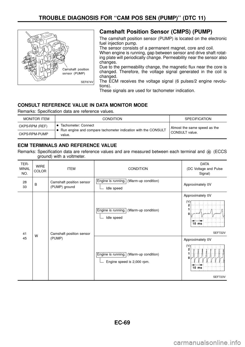
Camshaft Position Sensor (CMPS) (PUMP)
The camshaft position sensor (PUMP) is located on the electronic
fuel injection pump.
The sensor consists of a permanent magnet, core and coil.
When engine is running, gap between sensor and drive shaft rotat-
ing plate will periodically change. Permeability near the sensor also
changes.
Due to the permeability change, the magnetic ¯ux near the core is
changed. Therefore, the voltage signal generated in the coil is
changed.
The ECM receives the voltage signal (6 pulses/2 engine revolu-
tions).
These signals are used for tachometer indication.
CONSULT REFERENCE VALUE IN DATA MONITOR MODE
Remarks: Speci®cation data are reference values.
MONITOR ITEM CONDITION SPECIFICATION
CKPSzRPM (REF)+Tachometer: Connect
+Run engine and compare tachometer indication with the CONSULT
value.Almost the same speed as the
CONSULT value.
CKPSzRPM-PUMP
ECM TERMINALS AND REFERENCE VALUE
Remarks: Speci®cation data are reference values and are measured between each terminal andV43(ECCS
ground) with a voltmeter.
TER-
MINAL
NO.WIRE
COLORITEM CONDITIONDATA
(DC Voltage and Pulse
Signal)
28
33BCamshaft position sensor
(PUMP) groundEngine is running.
(Warm-up condition)
Idle speedApproximately 0V
41
45WCamshaft position sensor
(PUMP)Engine is running.
(Warm-up condition)
Idle speedApproximately 0V
SEF722V
Engine is running.(Warm-up condition)
Engine speed is 2,000 rpm.Approximately 0V
SEF723V
SEF674V
TROUBLE DIAGNOSIS FOR ``CAM POS SEN (PUMP)'' (DTC 11)
EC-69
Page 72 of 192
ON BOARD DIAGNOSIS LOGIC
Diagnostic
Trouble Code
No.Malfunction is detected when ....Check Items
(Possible cause)
11+An improper signal from the sensor is detected by
ECM during engine running.+Harness or connectors
[The camshaft position sensor (PUMP) circuit is open
or shorted.]
+Camshaft position sensor (PUMP)
DIAGNOSTIC TROUBLE CODE CONFIRMATION
PROCEDURE
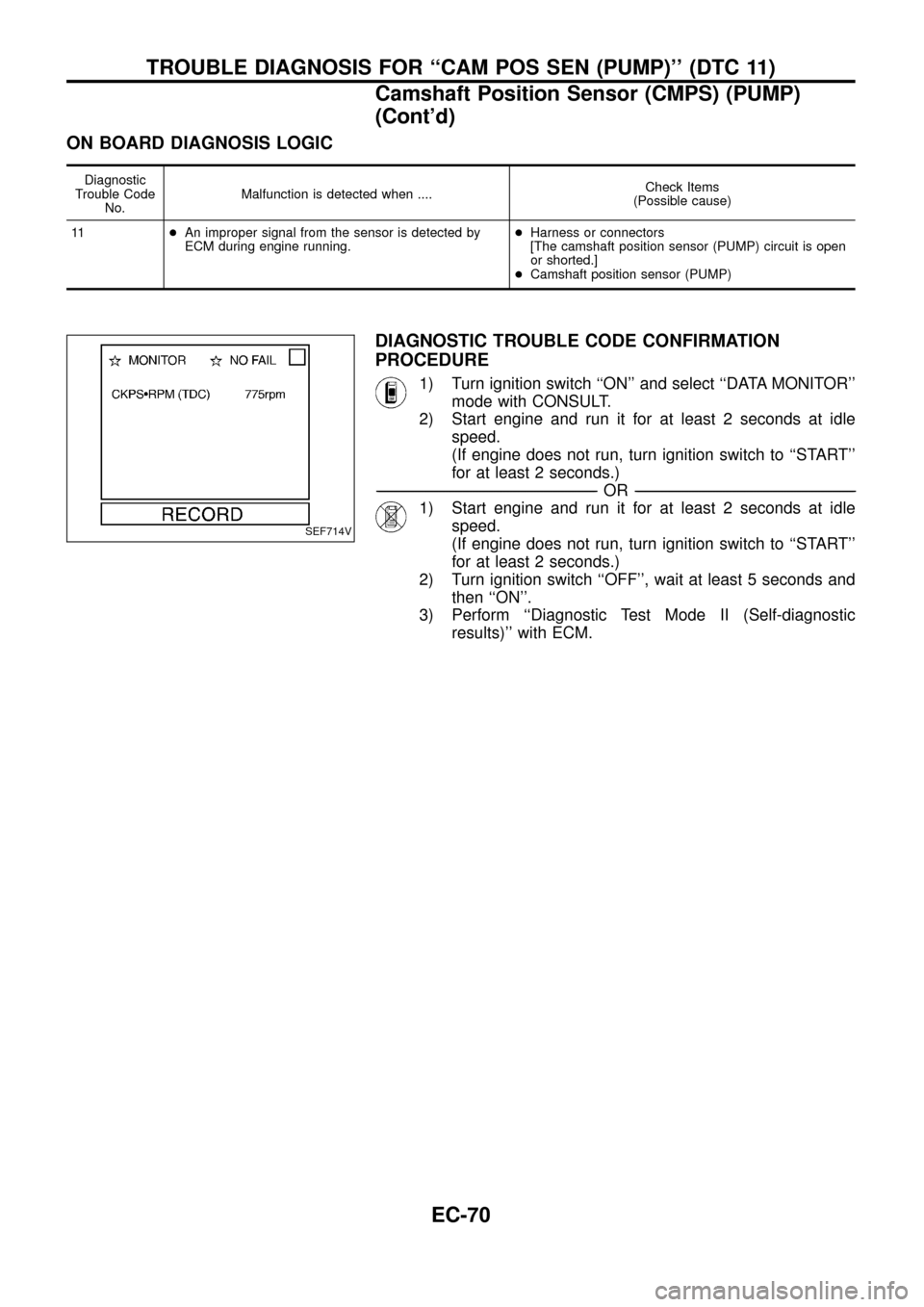
1) Turn ignition switch ``ON'' and select ``DATA MONITOR''
mode with CONSULT.
2) Start engine and run it for at least 2 seconds at idle
speed.
(If engine does not run, turn ignition switch to ``START''
for at least 2 seconds.)
-------------------------------------------------------------------------------------------------------------------------------------------------------------------------------------------------------------------------------------------------------OR-------------------------------------------------------------------------------------------------------------------------------------------------------------------------------------------------------------------------------------------------------
1) Start engine and run it for at least 2 seconds at idle
speed.
(If engine does not run, turn ignition switch to ``START''
for at least 2 seconds.)
2) Turn ignition switch ``OFF'', wait at least 5 seconds and
then ``ON''.
3) Perform ``Diagnostic Test Mode II (Self-diagnostic
results)'' with ECM.
SEF714V
TROUBLE DIAGNOSIS FOR ``CAM POS SEN (PUMP)'' (DTC 11)
Camshaft Position Sensor (CMPS) (PUMP)
(Cont'd)
EC-70
Page 73 of 192
TEC423
TROUBLE DIAGNOSIS FOR ``CAM POS SEN (PUMP)'' (DTC 11)
Camshaft Position Sensor (CMPS) (PUMP)
(Cont'd)
EC-71
Page 74 of 192
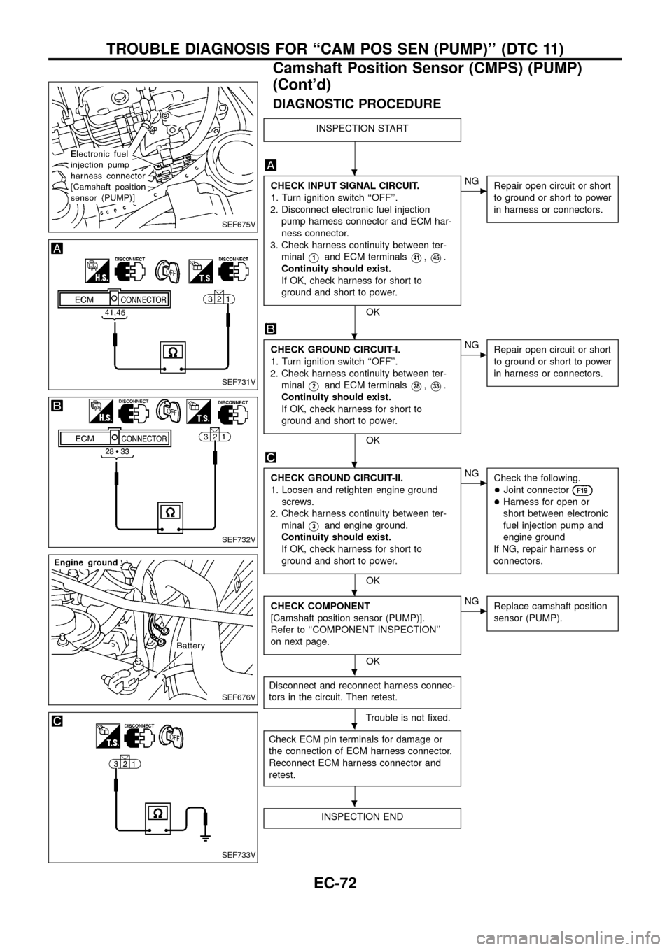
DIAGNOSTIC PROCEDURE
INSPECTION START
CHECK INPUT SIGNAL CIRCUIT.
1. Turn ignition switch ``OFF''.
2. Disconnect electronic fuel injection
pump harness connector and ECM har-
ness connector.
3. Check harness continuity between ter-
minal
V1and ECM terminalsV41,V45.
Continuity should exist.
If OK, check harness for short to
ground and short to power.
OK
cNG
Repair open circuit or short
to ground or short to power
in harness or connectors.
CHECK GROUND CIRCUIT-I.
1. Turn ignition switch ``OFF''.
2. Check harness continuity between ter-
minal
V2and ECM terminalsV28,V33.
Continuity should exist.
If OK, check harness for short to
ground and short to power.
OK
cNG
Repair open circuit or short
to ground or short to power
in harness or connectors.
CHECK GROUND CIRCUIT-II.
1. Loosen and retighten engine ground
screws.
2. Check harness continuity between ter-
minal
V3and engine ground.
Continuity should exist.
If OK, check harness for short to
ground and short to power.
OK
cNG
Check the following.
+Joint connector
F19
+Harness for open or
short between electronic
fuel injection pump and
engine ground
If NG, repair harness or
connectors.
CHECK COMPONENT
[Camshaft position sensor (PUMP)].
Refer to ``COMPONENT INSPECTION''
on next page.
OK
cNG
Replace camshaft position
sensor (PUMP).
Disconnect and reconnect harness connec-
tors in the circuit. Then retest.
Trouble is not ®xed.
Check ECM pin terminals for damage or
the connection of ECM harness connector.
Reconnect ECM harness connector and
retest.
INSPECTION END
SEF675V
SEF731V
SEF732V
SEF676V
SEF733V
.
.
.
.
.
.
.
TROUBLE DIAGNOSIS FOR ``CAM POS SEN (PUMP)'' (DTC 11)
Camshaft Position Sensor (CMPS) (PUMP)
(Cont'd)
EC-72
Page 75 of 192
COMPONENT INSPECTION
Camshaft position sensor (PUMP)
1. Disconnect electronic fuel injection pump harness connector.
2. Loosen the camshaft position sensor (PUMP).
3. Remove the sensor.
4. Visually check the sensor for chipping.
5. Check resistance between terminals
V1andV2.
Resistance:
Approximately 1,360 - 1,840W[at 25ÉC (77ÉF)]
If NG, replace camshaft position sensor (PUMP).
SEF573S
SEF677V
TROUBLE DIAGNOSIS FOR ``CAM POS SEN (PUMP)'' (DTC 11)
Camshaft Position Sensor (CMPS) (PUMP)
(Cont'd)
EC-73
Page 151 of 192
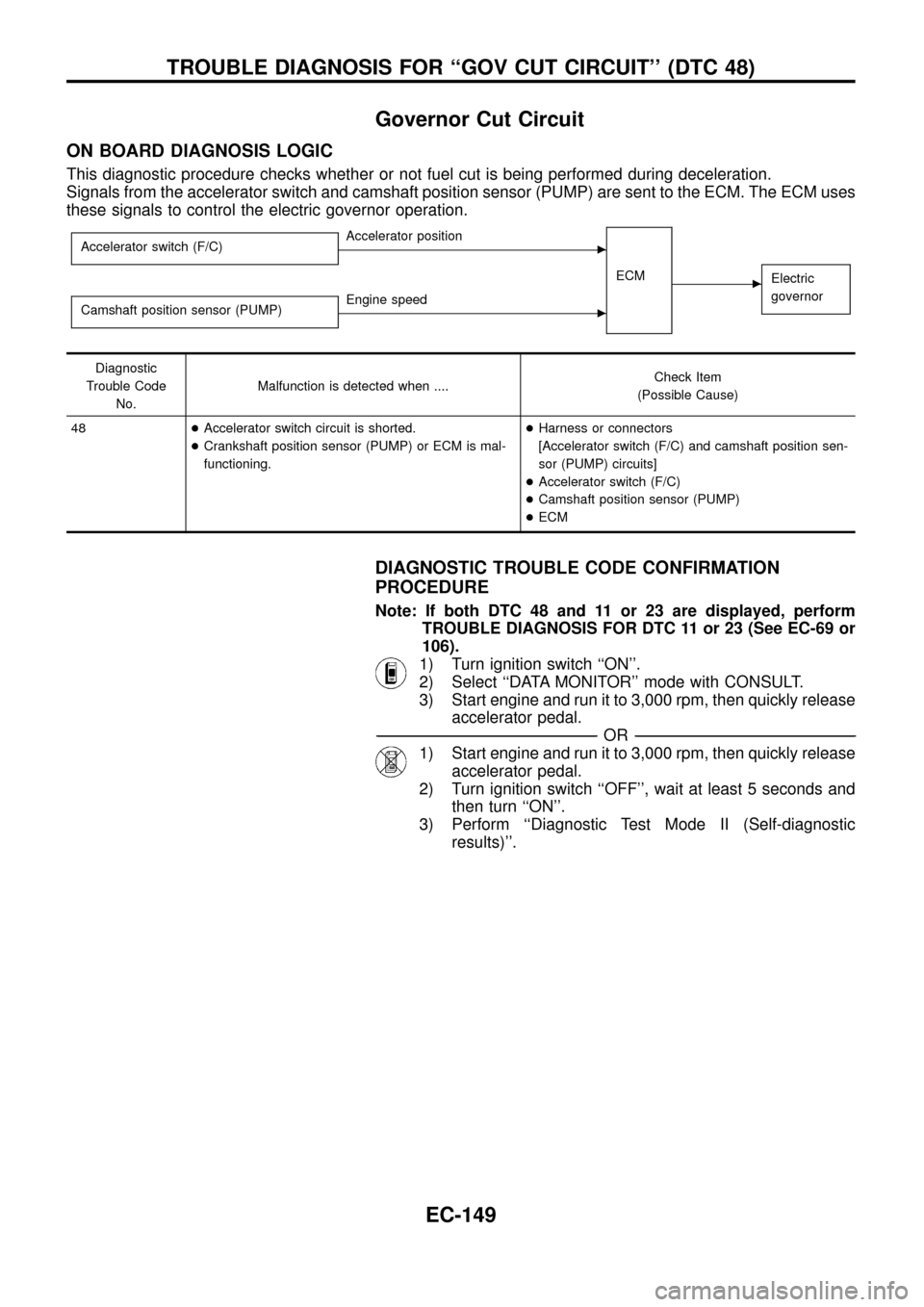
Governor Cut Circuit
ON BOARD DIAGNOSIS LOGIC
This diagnostic procedure checks whether or not fuel cut is being performed during deceleration.
Signals from the accelerator switch and camshaft position sensor (PUMP) are sent to the ECM. The ECM uses
these signals to control the electric governor operation.
Accelerator switch (F/C)cAccelerator position
ECM
cElectric
governor
Camshaft position sensor (PUMP)cEngine speed
Diagnostic
Trouble Code
No.Malfunction is detected when ....Check Item
(Possible Cause)
48+Accelerator switch circuit is shorted.
+Crankshaft position sensor (PUMP) or ECM is mal-
functioning.+Harness or connectors
[Accelerator switch (F/C) and camshaft position sen-
sor (PUMP) circuits]
+Accelerator switch (F/C)
+Camshaft position sensor (PUMP)
+ECM
DIAGNOSTIC TROUBLE CODE CONFIRMATION
PROCEDURE
Note: If both DTC 48 and 11 or 23 are displayed, perform
TROUBLE DIAGNOSIS FOR DTC 11 or 23 (See EC-69 or
106).
1) Turn ignition switch ``ON''.
2) Select ``DATA MONITOR'' mode with CONSULT.
3) Start engine and run it to 3,000 rpm, then quickly release
accelerator pedal.
-------------------------------------------------------------------------------------------------------------------------------------------------------------------------------------------------------------------------------------------------------OR-------------------------------------------------------------------------------------------------------------------------------------------------------------------------------------------------------------------------------------------------------
1) Start engine and run it to 3,000 rpm, then quickly release
accelerator pedal.
2) Turn ignition switch ``OFF'', wait at least 5 seconds and
then turn ``ON''.
3) Perform ``Diagnostic Test Mode II (Self-diagnostic
results)''.
TROUBLE DIAGNOSIS FOR ``GOV CUT CIRCUIT'' (DTC 48)
EC-149
Page 158 of 192
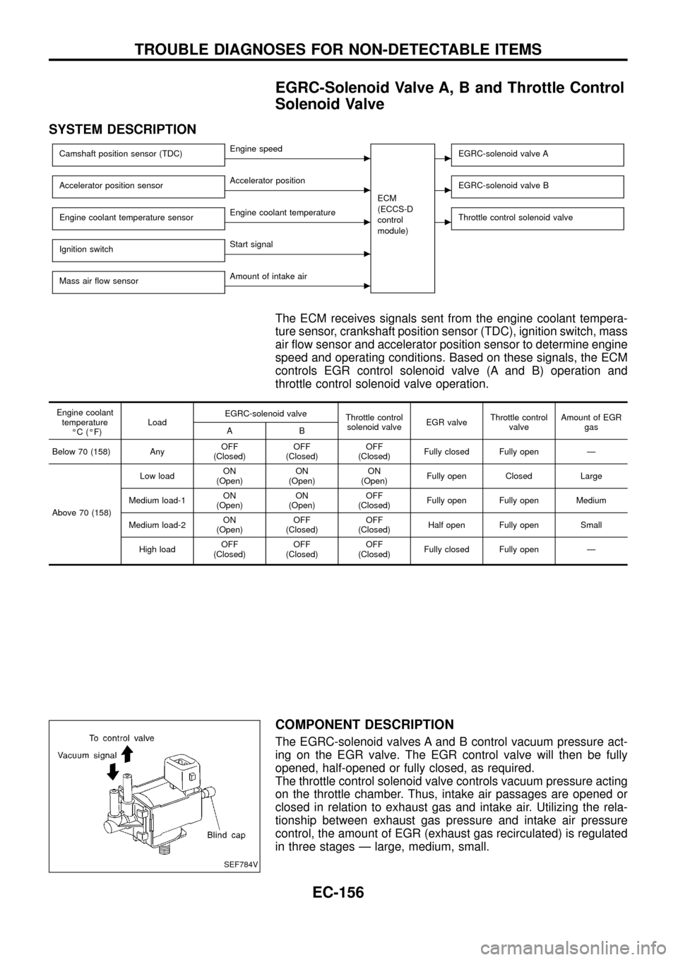
EGRC-Solenoid Valve A, B and Throttle Control
Solenoid Valve
SYSTEM DESCRIPTION
Camshaft position sensor (TDC)cEngine speed
ECM
(ECCS-D
control
module)cEGRC-solenoid valve A
Accelerator position sensorcAccelerator positioncEGRC-solenoid valve B
Engine coolant temperature sensorcEngine coolant temperaturecThrottle control solenoid valve
Ignition switchcStart signal
Mass air ¯ow sensor
cAmount of intake air
The ECM receives signals sent from the engine coolant tempera-
ture sensor, crankshaft position sensor (TDC), ignition switch, mass
air ¯ow sensor and accelerator position sensor to determine engine
speed and operating conditions. Based on these signals, the ECM
controls EGR control solenoid valve (A and B) operation and
throttle control solenoid valve operation.
Engine coolant
temperature
ÉC (ÉF)LoadEGRC-solenoid valve
Throttle control
solenoid valveEGR valveThrottle control
valveAmount of EGR
gas
AB
Below 70 (158) AnyOFF
(Closed)OFF
(Closed)OFF
(Closed)Fully closed Fully open Ð
Above 70 (158)Low loadON
(Open)ON
(Open)ON
(Open)Fully open Closed Large
Medium load-1ON
(Open)ON
(Open)OFF
(Closed)Fully open Fully open Medium
Medium load-2ON
(Open)OFF
(Closed)OFF
(Closed)Half open Fully open Small
High loadOFF
(Closed)OFF
(Closed)OFF
(Closed)Fully closed Fully open Ð
COMPONENT DESCRIPTION
The EGRC-solenoid valves A and B control vacuum pressure act-
ing on the EGR valve. The EGR control valve will then be fully
opened, half-opened or fully closed, as required.
The throttle control solenoid valve controls vacuum pressure acting
on the throttle chamber. Thus, intake air passages are opened or
closed in relation to exhaust gas and intake air. Utilizing the rela-
tionship between exhaust gas pressure and intake air pressure
control, the amount of EGR (exhaust gas recirculated) is regulated
in three stages Ð large, medium, small.
SEF784V
TROUBLE DIAGNOSES FOR NON-DETECTABLE ITEMS
EC-156