Page 57 of 326

Trouble Diagnoses
Before conducting an alternator test, make sure that the battery is fully charged. A 30-volt voltmeter and suit-
able test probes are necessary for the test. The alternator can be checked easily by referring to the Inspec-
tion Table.
+Before starting, inspect the fusible link.
+Use fully charged battery.
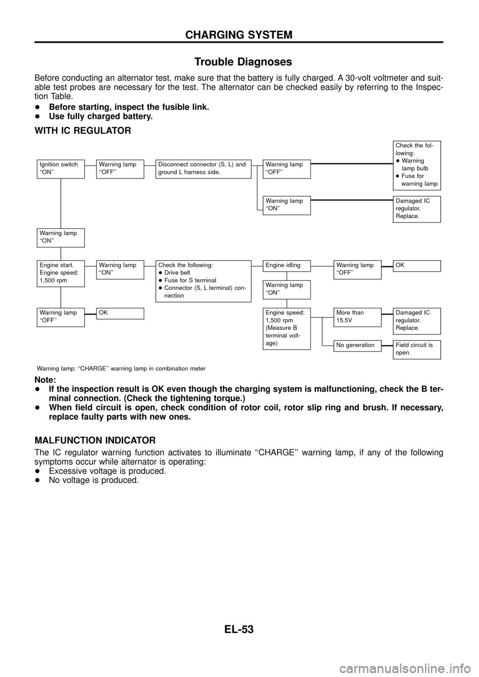
WITH IC REGULATOR
Check the fol-
lowing:
+Warning
lamp bulb
+Fuse for
warning lamp
Ignition switch
``ON''Warning lamp
``OFF''Disconnect connector (S, L) and
ground L harness side.Warning lamp
``OFF''
Warning lamp
``ON''Damaged IC
regulator.
Replace.
Warning lamp
``ON''
Engine start.
Engine speed:
1,500 rpmWarning lamp
``ON''Check the following:
+Drive belt
+Fuse for S terminal
+Connector (S, L terminal) con-
nectionEngine idlingWarning lamp
``OFF''OK
Warning lamp
``ON''
Warning lamp
``OFF''OKEngine speed:
1,500 rpm
(Measure B
terminal volt-
age)More than
15.5VDamaged IC
regulator.
Replace.
No generationField circuit is
open.
Warning lamp: ``CHARGE'' warning lamp in combination meter
Note:
+If the inspection result is OK even though the charging system is malfunctioning, check the B ter-
minal connection. (Check the tightening torque.)
+When ®eld circuit is open, check condition of rotor coil, rotor slip ring and brush. If necessary,
replace faulty parts with new ones.
MALFUNCTION INDICATOR
The IC regulator warning function activates to illuminate ``CHARGE'' warning lamp, if any of the following
symptoms occur while alternator is operating:
+Excessive voltage is produced.
+No voltage is produced.
CHARGING SYSTEM
EL-53
Page 89 of 326

Trouble Diagnoses
Symptom Possible cause Repair order
Turn signal and hazard warning
lamps do not operate.1. Hazard switch
2. Combination ¯asher unit
3. Open in combination ¯asher unit
circuit1. Check hazard switch.
2. Refer to combination ¯asher unit check.
3. Check wiring to combination ¯asher unit for open cir-
cuit.
Turn signal lamps do not operate
but hazard warning lamps operate.1. 7.5A fuse
2. Hazard switch
3. Turn signal switch
4. Open in turn signal switch circuit1. Check 7.5A fuse [No.
11, located in fuse block
(J/B)]. Turn ignition switch ON and verify battery
positive voltage is present at terminalj
2of hazard
switch.
2. Check hazard switch.
3. Check turn signal switch.
4. Check harness between combination ¯asher unit and
turn signal switch for open circuit.
Hazard warning lamps do not oper-
ate but turn signal lamps operate.1. 15A fuse
2. Hazard switch
3. Open in hazard switch circuit1. Check 10A fuse (No.
48, located in fuse and fusible
link box). Verify battery positive voltage is present at
terminalj
3of hazard switch.
2. Check hazard switch.
3. Check harness between combination ¯asher unit and
hazard switch for open circuit.
Front turn signal lamp LH or RH
does not operate.1. Bulb
2. Grounds
E25andE40
1. Check bulb.
2. Check grounds
E25andE40.
Rear turn signal lamp LH or RH
does not operate.1. Bulb
2. Grounds
B23andD83or
B112andD106
1. Check bulb.
2. Check grounds
B23andD83orB112andD106.
LH and RH turn indicators do not
operate.1. Ground 1. Check grounds
M30andM98.
LH or RH turn indicator does not
operate.1. Bulb 1. Check bulb in combination meter.
Electrical Components Inspection
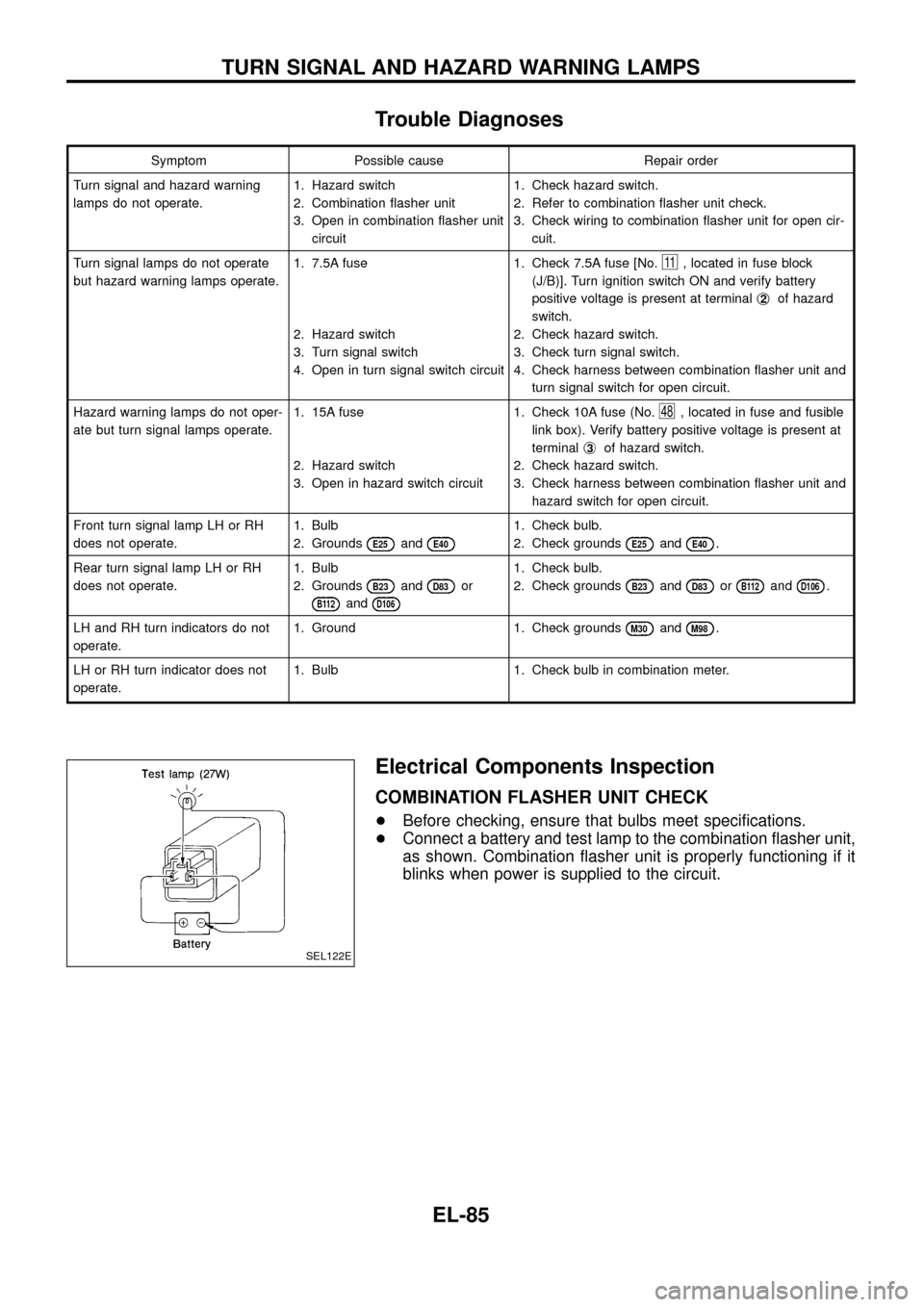
COMBINATION FLASHER UNIT CHECK
+Before checking, ensure that bulbs meet speci®cations.
+Connect a battery and test lamp to the combination ¯asher unit,
as shown. Combination ¯asher unit is properly functioning if it
blinks when power is supplied to the circuit.
SEL122E
TURN SIGNAL AND HAZARD WARNING LAMPS
EL-85
Page 104 of 326

Trouble Diagnoses
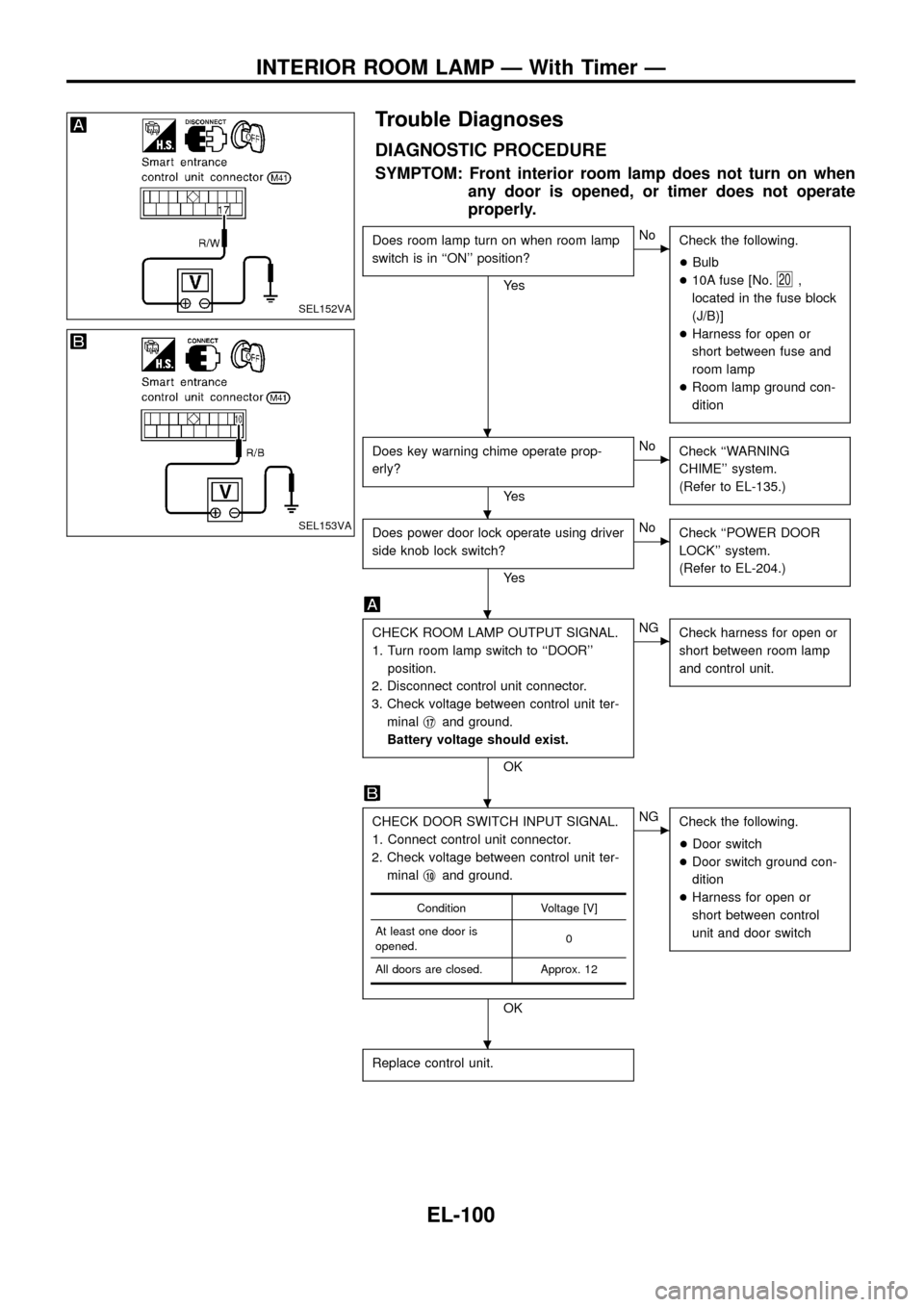
DIAGNOSTIC PROCEDURE
SYMPTOM: Front interior room lamp does not turn on when
any door is opened, or timer does not operate
properly.
Does room lamp turn on when room lamp
switch is in ``ON'' position?
Ye s
cNo
Check the following.
+Bulb
+10A fuse [No.
20,
located in the fuse block
(J/B)]
+Harness for open or
short between fuse and
room lamp
+Room lamp ground con-
dition
Does key warning chime operate prop-
erly?
Ye s
cNo
Check ``WARNING
CHIME'' system.
(Refer to EL-135.)
Does power door lock operate using driver
side knob lock switch?
Ye s
cNo
Check ``POWER DOOR
LOCK'' system.
(Refer to EL-204.)
CHECK ROOM LAMP OUTPUT SIGNAL.
1. Turn room lamp switch to ``DOOR''
position.
2. Disconnect control unit connector.
3. Check voltage between control unit ter-
minalj
17and ground.
Battery voltage should exist.
OK
cNG
Check harness for open or
short between room lamp
and control unit.
CHECK DOOR SWITCH INPUT SIGNAL.
1. Connect control unit connector.
2. Check voltage between control unit ter-
minalj
10and ground.
OK
cNG
Check the following.
+Door switch
+Door switch ground con-
dition
+Harness for open or
short between control
unit and door switch
Replace control unit.
Condition Voltage [V]
At least one door is
opened.0
All doors are closed. Approx. 12
SEL152VA
SEL153VA
.
.
.
.
.
INTERIOR ROOM LAMP Ð With Timer Ð
EL-100
Page 138 of 326
Electrical Components Inspection
FUEL WARNING LAMP SENSOR CHECK
+It will take a short time for the bulb to light.
NOTE: Inspection for sub fuel warning lamp sensor is the
same as for fuel warning lamp sensor.
OIL PRESSURE SWITCH CHECK
Oil pressure
kPa (bar, kg/cm2, psi)Continuity
Engine startMore than 10 - 20
(0.10 - 0.20, 0.1 - 0.2,1-3)NO
Engine stopLess than 10 - 20
(0.10 - 0.20, 0.1 - 0.2,1-3)YES
Check the continuity between the terminals of oil pressure switch
and body ground.
DIODE CHECK
+Check continuity using an ohmmeter.
+Diode is functioning properly if test results are as shown in the
®gure at left.
NOTE: Speci®cation may vary depending on the type of tester.
Before performing this inspection, be sure to refer to
the instruction manual for the tester to be used.
+Diodes for warning lamps are built into the combination meter
printed circuit.
MEL828F
MEL425F
CEL520
CEL740
WARNING LAMPS
EL-134