1998 NISSAN PATROL sen
[x] Cancel search: senPage 3 of 326
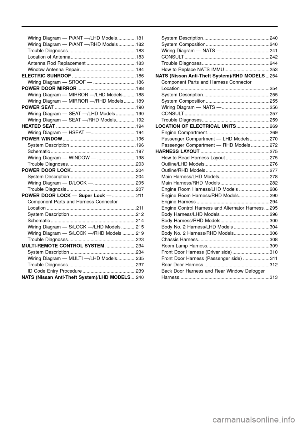
Wiring Diagram Ð P/ANT Ð/LHD Models..............181
Wiring Diagram Ð P/ANT Ð/RHD Models .............182
Trouble Diagnoses...................................................183
Location of Antenna .................................................183
Antenna Rod Replacement .....................................183
Window Antenna Repair ..........................................184
ELECTRIC SUNROOF................................................186
Wiring Diagram Ð SROOF Ð ................................186
POWER DOOR MIRROR............................................188
Wiring Diagram Ð MIRROR Ð/LHD Models..........188
Wiring Diagram Ð MIRROR Ð/RHD Models .........189
POWER SEAT.............................................................190
Wiring Diagram Ð SEAT Ð/LHD Models ...............190
Wiring Diagram Ð SEAT Ð/RHD Models...............192
HEATED SEAT............................................................194
Wiring Diagram Ð HSEAT Ð..................................194
POWER WINDOW.......................................................196
System Description ..................................................196
Schematic ................................................................197
Wiring Diagram Ð WINDOW Ð .............................198
Trouble Diagnoses...................................................203
POWER DOOR LOCK.................................................204
System Description ..................................................204
Wiring Diagram Ð D/LOCK Ð ................................205
Trouble Diagnosis ....................................................207
POWER DOOR LOCK Ð Super Lock Ð.................. 211
Component Parts and Harness Connector
Location ................................................................... 211
System Description ..................................................212
Schematic ................................................................214
Wiring Diagram Ð S/LOCK Ð/LHD Models ...........215
Wiring Diagram Ð S/LOCK Ð/RHD Models ..........219
Trouble Diagnoses...................................................223
MULTI-REMOTE CONTROL SYSTEM.......................234
System Description ..................................................234
Wiring Diagram Ð MULTI Ð/LHD Models..............235
Trouble Diagnoses...................................................237
ID Code Entry Procedure ........................................239
NATS (Nissan Anti-Theft System)/LHD MODELS....240System Description ..................................................240
System Composition ................................................240
Wiring Diagram Ð NATS Ð ....................................241
CONSULT ................................................................242
Trouble Diagnoses...................................................244
How to Replace NATS IMMU ..................................253
NATS (Nissan Anti-Theft System)/RHD MODELS...254
Component Parts and Harness Connector
Location ...................................................................254
System Description ..................................................255
System Composition ................................................255
Wiring Diagram Ð NATS Ð ....................................256
CONSULT ................................................................257
Trouble Diagnoses...................................................259
LOCATION OF ELECTRICAL UNITS.........................269
Engine Compartment ...............................................269
Passenger Compartment Ð LHD Models ...............270
Passenger Compartment Ð RHD Models ..............272
HARNESS LAYOUT....................................................275
How to Read Harness Layout .................................275
Outline/LHD Models.................................................276
Outline/RHD Models ................................................277
Main Harness/LHD Models......................................278
Main Harness/RHD Models .....................................282
Engine Room Harness/LHD Models .......................286
Engine Room Harness/RHD Models .......................290
Engine Harness .......................................................294
Engine Control Harness and Alternator Harness ....295
Body Harness/LHD Models .....................................296
Body Harness/RHD Models.....................................300
Body No. 2 Harness/LHD Models ...........................304
Body No. 2 Harness/RHD Models...........................306
Chassis Harness......................................................308
Room Lamp Harness...............................................309
Front Door Harness (Driver side) ............................310
Front Door Harness (Passenger side) .................... 311
Rear Door Harness..................................................312
Back Door Harness and Rear Window Defogger
Harness....................................................................313
Page 5 of 326
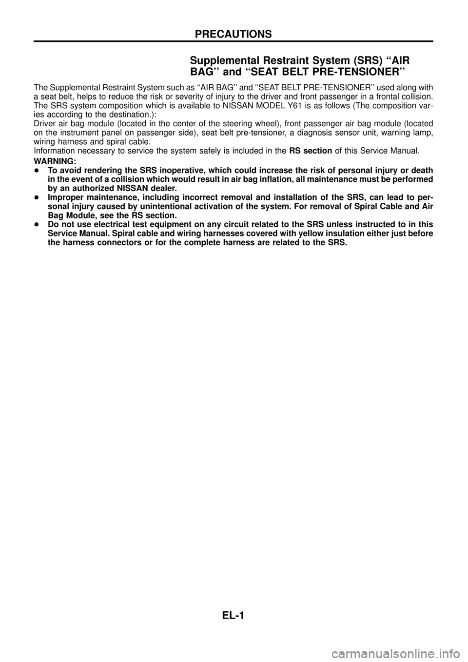
Supplemental Restraint System (SRS) ``AIR
BAG'' and ``SEAT BELT PRE-TENSIONER''
The Supplemental Restraint System such as ``AIR BAG'' and ``SEAT BELT PRE-TENSIONER'' used along with
a seat belt, helps to reduce the risk or severity of injury to the driver and front passenger in a frontal collision.
The SRS system composition which is available to NISSAN MODEL Y61 is as follows (The composition var-
ies according to the destination.):
Driver air bag module (located in the center of the steering wheel), front passenger air bag module (located
on the instrument panel on passenger side), seat belt pre-tensioner, a diagnosis sensor unit, warning lamp,
wiring harness and spiral cable.
Information necessary to service the system safely is included in theRS sectionof this Service Manual.
WARNING:
+To avoid rendering the SRS inoperative, which could increase the risk of personal injury or death
in the event of a collision which would result in air bag in¯ation, all maintenance must be performed
by an authorized NISSAN dealer.
+Improper maintenance, including incorrect removal and installation of the SRS, can lead to per-
sonal injury caused by unintentional activation of the system. For removal of Spiral Cable and Air
Bag Module, see the RS section.
+Do not use electrical test equipment on any circuit related to the SRS unless instructed to in this
Service Manual. Spiral cable and wiring harnesses covered with yellow insulation either just before
the harness connectors or for the complete harness are related to the SRS.
PRECAUTIONS
EL-1
Page 6 of 326
Description
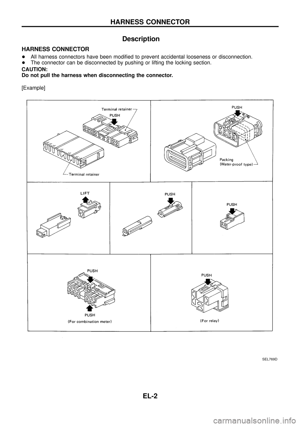
HARNESS CONNECTOR
+All harness connectors have been modi®ed to prevent accidental looseness or disconnection.
+The connector can be disconnected by pushing or lifting the locking section.
CAUTION:
Do not pull the harness when disconnecting the connector.
[Example]
SEL769D
HARNESS CONNECTOR
EL-2
Page 66 of 326
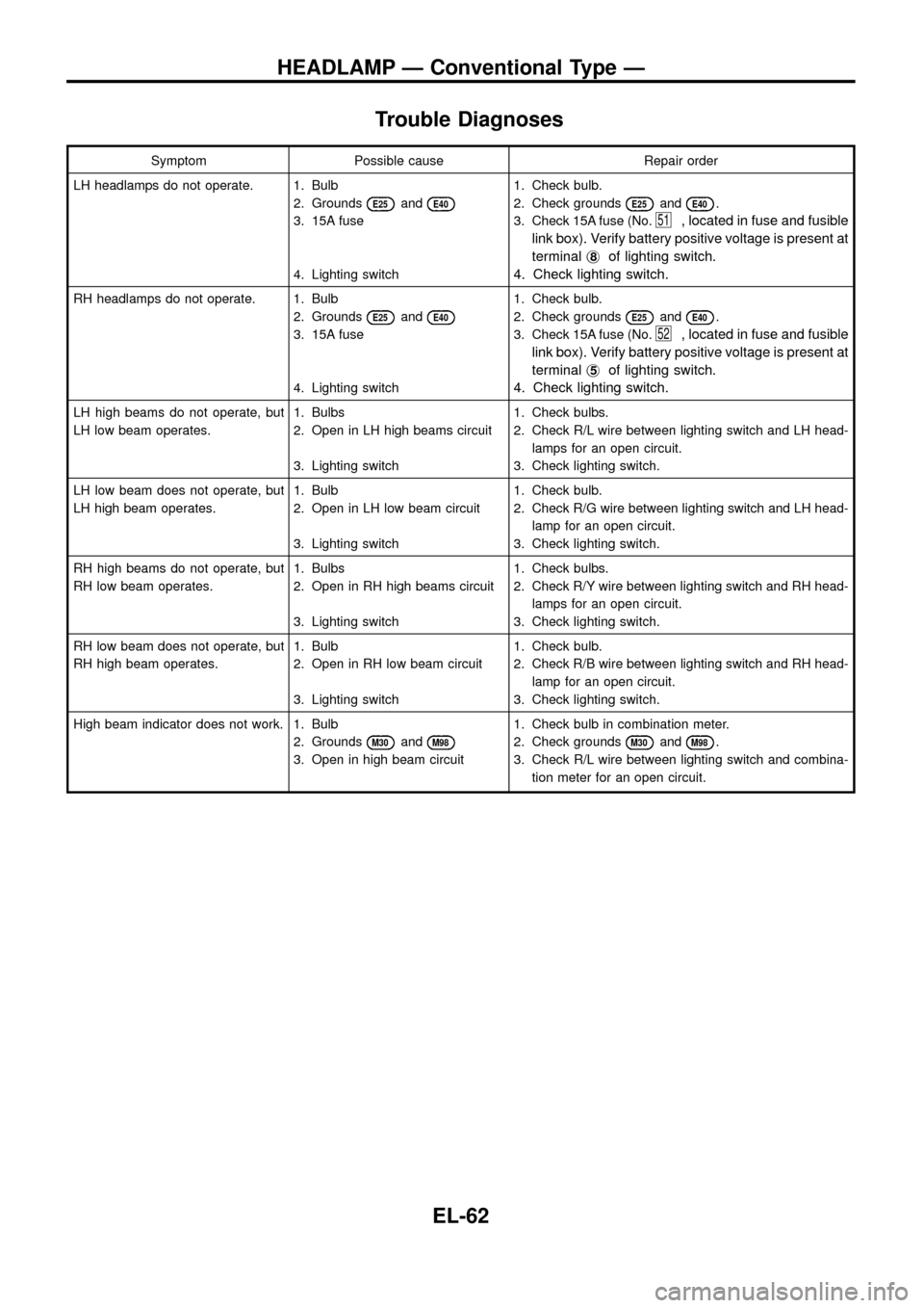
Trouble Diagnoses
Symptom Possible cause Repair order
LH headlamps do not operate. 1. Bulb
2. Grounds
E25andE40
3. 15A fuse
4. Lighting switch1. Check bulb.
2. Check grounds
E25andE40.
3. Check 15A fuse (No.
51, located in fuse and fusible
link box). Verify battery positive voltage is present at
terminalj
8of lighting switch.
4. Check lighting switch.
RH headlamps do not operate. 1. Bulb
2. Grounds
E25andE40
3. 15A fuse
4. Lighting switch1. Check bulb.
2. Check grounds
E25andE40.
3. Check 15A fuse (No.
52, located in fuse and fusible
link box). Verify battery positive voltage is present at
terminalj
5of lighting switch.
4. Check lighting switch.
LH high beams do not operate, but
LH low beam operates.1. Bulbs
2. Open in LH high beams circuit
3. Lighting switch1. Check bulbs.
2. Check R/L wire between lighting switch and LH head-
lamps for an open circuit.
3. Check lighting switch.
LH low beam does not operate, but
LH high beam operates.1. Bulb
2. Open in LH low beam circuit
3. Lighting switch1. Check bulb.
2. Check R/G wire between lighting switch and LH head-
lamp for an open circuit.
3. Check lighting switch.
RH high beams do not operate, but
RH low beam operates.1. Bulbs
2. Open in RH high beams circuit
3. Lighting switch1. Check bulbs.
2. Check R/Y wire between lighting switch and RH head-
lamps for an open circuit.
3. Check lighting switch.
RH low beam does not operate, but
RH high beam operates.1. Bulb
2. Open in RH low beam circuit
3. Lighting switch1. Check bulb.
2. Check R/B wire between lighting switch and RH head-
lamp for an open circuit.
3. Check lighting switch.
High beam indicator does not work. 1. Bulb
2. Grounds
M30andM98
3. Open in high beam circuit1. Check bulb in combination meter.
2. Check grounds
M30andM98.
3. Check R/L wire between lighting switch and combina-
tion meter for an open circuit.
HEADLAMP Ð Conventional Type Ð
EL-62
Page 68 of 326
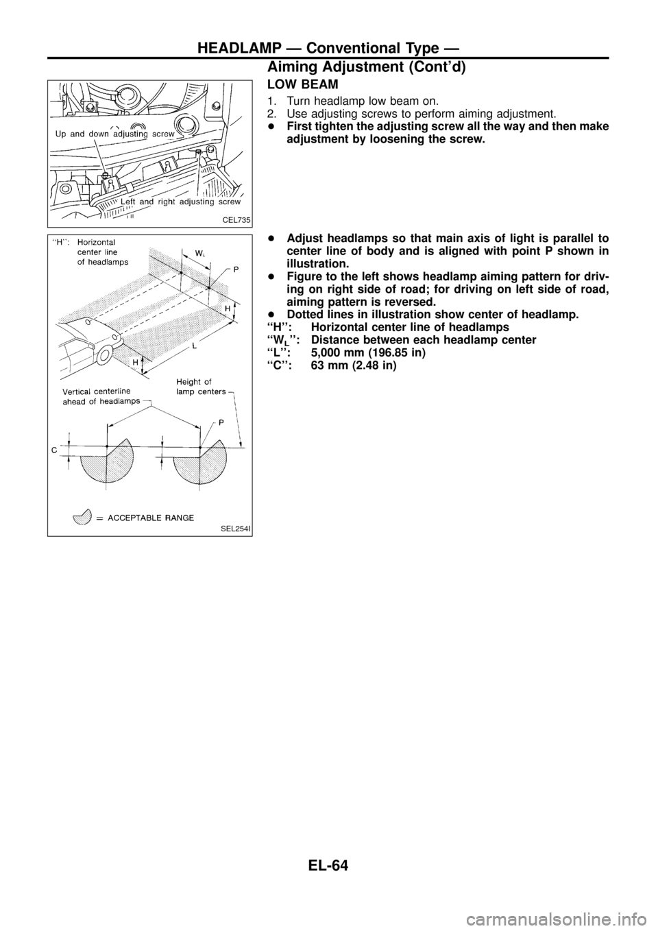
LOW BEAM
1. Turn headlamp low beam on.
2. Use adjusting screws to perform aiming adjustment.
+First tighten the adjusting screw all the way and then make
adjustment by loosening the screw.
+Adjust headlamps so that main axis of light is parallel to
center line of body and is aligned with point P shown in
illustration.
+Figure to the left shows headlamp aiming pattern for driv-
ing on right side of road; for driving on left side of road,
aiming pattern is reversed.
+Dotted lines in illustration show center of headlamp.
``H'': Horizontal center line of headlamps
``W
L'': Distance between each headlamp center
``L'': 5,000 mm (196.85 in)
``C'': 63 mm (2.48 in)
CEL735
SEL254I
HEADLAMP Ð Conventional Type Ð
Aiming Adjustment (Cont'd)
EL-64
Page 74 of 326
![NISSAN PATROL 1998 Y61 / 5.G Electrical System Workshop Manual System Description
CIRCUIT OPERATION
[Example]
Aiming switch ``0
+When the aiming switch is set to ``0, the motor will not start.
This is because the power terminals are positioned at the non-
con NISSAN PATROL 1998 Y61 / 5.G Electrical System Workshop Manual System Description
CIRCUIT OPERATION
[Example]
Aiming switch ``0
+When the aiming switch is set to ``0, the motor will not start.
This is because the power terminals are positioned at the non-
con](/manual-img/5/616/w960_616-73.png)
System Description
CIRCUIT OPERATION
[Example]
Aiming switch ``0''
+When the aiming switch is set to ``0'', the motor will not start.
This is because the power terminals are positioned at the non-
conductive section of the sensor's rotary unit.
Aiming switch ``0''®``1''
+When the aiming switch is moved from ``0'' to ``1'', the sensor's
conductive section activates the relay. Power is supplied
through the relay to the motor. The headlamps will then move
in the ``DOWN'' direction.
+The motor continues to rotate while the rotary unit of the sen-
sor moves from point A to point B.
+The power terminals will then be positioned at the nonconduc-
tive section, disconnecting the power to the motor. The motor
will then stop.
Aiming switch ``1''®``0''
+When the aiming switch is moved from ``1'' to ``0'', the sensor's
conductive section activates the relay. Power is supplied
through the relay to the motor. The motor will rotate to move the
headlamps in the ``UP'' direction.
+When the rotary unit of the sensor moves from point B to point
A, the motor will stop.
SEL465M
SEL364P
SEL365P
HEADLAMP Ð Headlamp Aiming Control Ð
EL-70
Page 89 of 326
Trouble Diagnoses
Symptom Possible cause Repair order
Turn signal and hazard warning
lamps do not operate.1. Hazard switch
2. Combination ¯asher unit
3. Open in combination ¯asher unit
circuit1. Check hazard switch.
2. Refer to combination ¯asher unit check.
3. Check wiring to combination ¯asher unit for open cir-
cuit.
Turn signal lamps do not operate
but hazard warning lamps operate.1. 7.5A fuse
2. Hazard switch
3. Turn signal switch
4. Open in turn signal switch circuit1. Check 7.5A fuse [No.
11, located in fuse block
(J/B)]. Turn ignition switch ON and verify battery
positive voltage is present at terminalj
2of hazard
switch.
2. Check hazard switch.
3. Check turn signal switch.
4. Check harness between combination ¯asher unit and
turn signal switch for open circuit.
Hazard warning lamps do not oper-
ate but turn signal lamps operate.1. 15A fuse
2. Hazard switch
3. Open in hazard switch circuit1. Check 10A fuse (No.
48, located in fuse and fusible
link box). Verify battery positive voltage is present at
terminalj
3of hazard switch.
2. Check hazard switch.
3. Check harness between combination ¯asher unit and
hazard switch for open circuit.
Front turn signal lamp LH or RH
does not operate.1. Bulb
2. Grounds
E25andE40
1. Check bulb.
2. Check grounds
E25andE40.
Rear turn signal lamp LH or RH
does not operate.1. Bulb
2. Grounds
B23andD83or
B112andD106
1. Check bulb.
2. Check grounds
B23andD83orB112andD106.
LH and RH turn indicators do not
operate.1. Ground 1. Check grounds
M30andM98.
LH or RH turn indicator does not
operate.1. Bulb 1. Check bulb in combination meter.
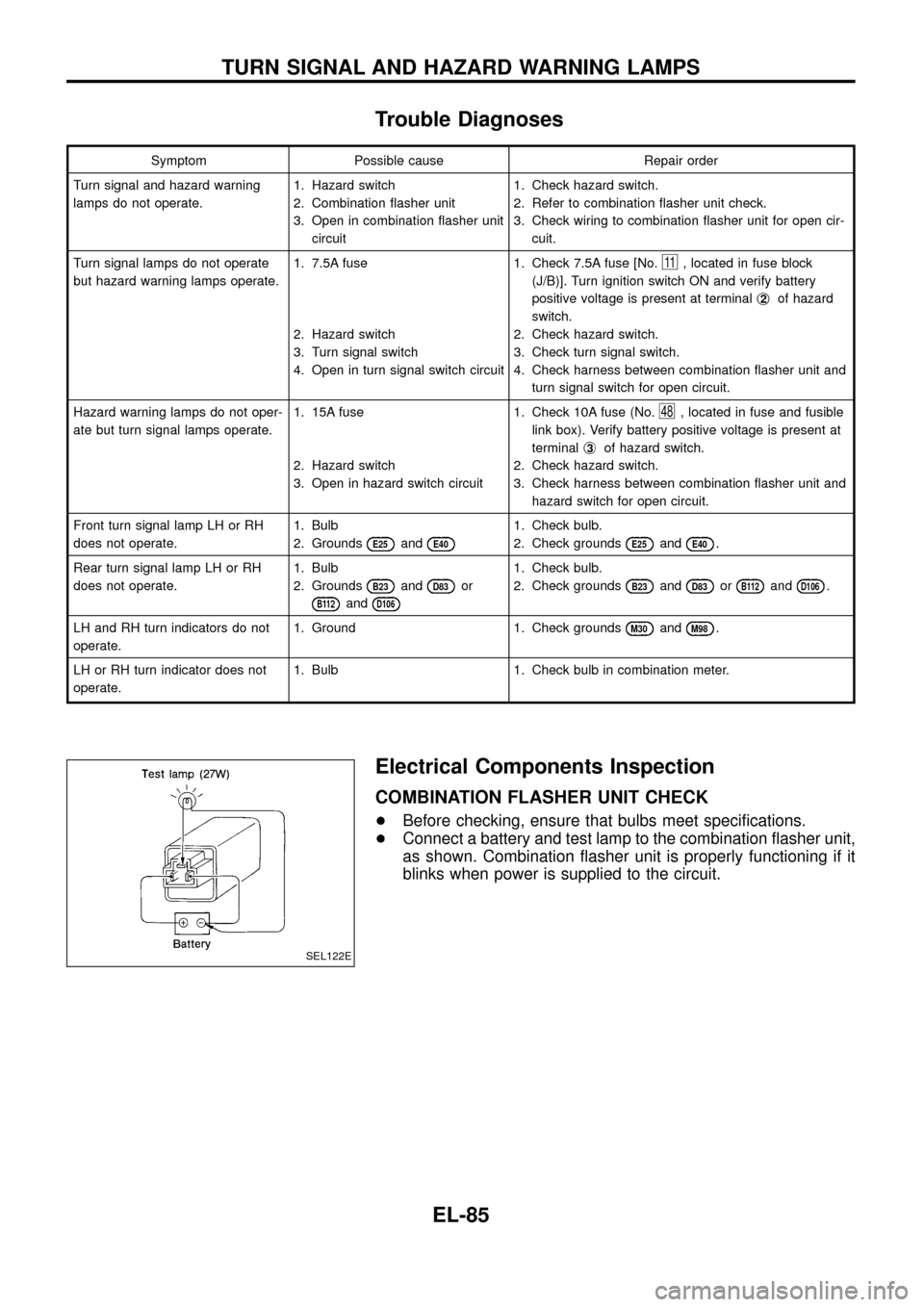
Electrical Components Inspection
COMBINATION FLASHER UNIT CHECK
+Before checking, ensure that bulbs meet speci®cations.
+Connect a battery and test lamp to the combination ¯asher unit,
as shown. Combination ¯asher unit is properly functioning if it
blinks when power is supplied to the circuit.
SEL122E
TURN SIGNAL AND HAZARD WARNING LAMPS
EL-85
Page 97 of 326
System Description
Front interior room lamp timer is controlled by smart entrance control unit while interior room lamp switch is
in the ``DOOR'' position.
Smart entrance control unit does not control rear interior room lamp.
TIMER OPERATION
Interior room lamp timer keeps interior room lamp illuminated for about 15 seconds when:
+driver's door is unlocked while key is out of ignition key cylinder,
+key is withdrawn from ignition key cylinder while driver's door is closed, and
+driver's door is opened and then closed while ignition switch is not in the ``ON'' position.
The timer is cancelled, and interior room lamp turns off when:
+driver's door is locked, or
+ignition switch is turned ``ON''.
ON-OFF CONTROL
When the front driver side door, front passenger side door, rear LH door, rear RH door or back door is opened,
interior room lamp turns on.
When driver side door is opened and then closed while ignition switch is not in the ON position, interior room
lamp timer operates. (Timer does not operate when doors other than the driver side door is opened and
closed.)
INTERIOR ROOM LAMP Ð With Timer Ð
EL-93