Page 52 of 326

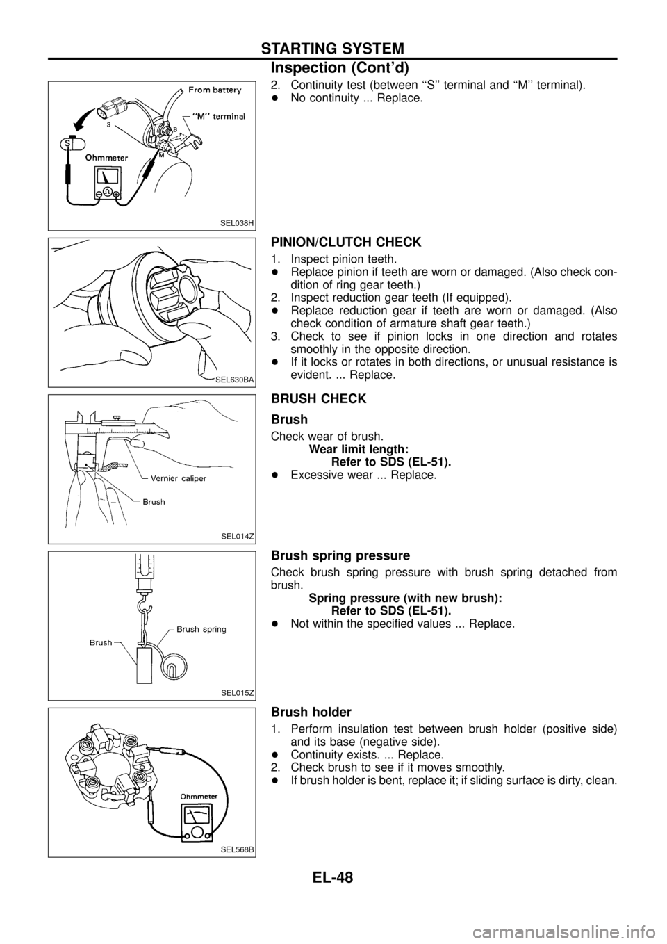
2. Continuity test (between ``S'' terminal and ``M'' terminal).
+No continuity ... Replace.
PINION/CLUTCH CHECK
1. Inspect pinion teeth.
+Replace pinion if teeth are worn or damaged. (Also check con-
dition of ring gear teeth.)
2. Inspect reduction gear teeth (If equipped).
+Replace reduction gear if teeth are worn or damaged. (Also
check condition of armature shaft gear teeth.)
3. Check to see if pinion locks in one direction and rotates
smoothly in the opposite direction.
+If it locks or rotates in both directions, or unusual resistance is
evident. ... Replace.
BRUSH CHECK
Brush
Check wear of brush.
Wear limit length:
Refer to SDS (EL-51).
+Excessive wear ... Replace.
Brush spring pressure
Check brush spring pressure with brush spring detached from
brush.
Spring pressure (with new brush):
Refer to SDS (EL-51).
+Not within the speci®ed values ... Replace.
Brush holder
1. Perform insulation test between brush holder (positive side)
and its base (negative side).
+Continuity exists. ... Replace.
2. Check brush to see if it moves smoothly.
+If brush holder is bent, replace it; if sliding surface is dirty, clean.
SEL038H
SEL630BA
SEL014Z
SEL015Z
SEL568B
STARTING SYSTEM
Inspection (Cont'd)
EL-48
Page 55 of 326
+Not in the speci®ed value ... Adjust by adjusting plate.
Service Data and Speci®cations (SDS)
STARTER
TypeS13-502
HITACHI make
Reduction gear type
Applied model RD28
System voltage V 12
No-load
Terminal voltage V 11
Current A Less than 125
Revolution rpm 4,000
Minimum diameter of commutator
mm (in)35.5 (1.398)
Minimum length of brush mm (in) 11 (0.43)
Brush spring tension
N (kg, lb)28.4 - 34.3
(2.9 - 3.5,
6.4 - 7.7)
Clearance between bearing metal
and armature shaft mm (in)Ð
Clearance ``!'' between pinion
front edge and pinion stopper
mm (in)Ð
Movement ``!'' in height of pinion
assembly mm (in)0.3 - 2.0
(0.012 - 0.079)
SEL633BA
STARTING SYSTEM
Assembly (Cont'd)
EL-51
Page 62 of 326
Replacement
For removal and installation of spiral cable, refer to RS section
[``Installation Ð Air Bag Module and Spiral Cable'', ``SUPPLE-
MENTAL RESTRAINT SYSTEM (SRS)''].
+Each switch can be replaced without removing combination
switch base.
+To remove combination switch base, remove base attaching
screw.
+Before installing the steering wheel, align the steering wheel
guide pins with the screws which secure the combination switch
as shown in the left ®gure.
MEL304D
MEL326G
SEL151V
COMBINATION SWITCH
EL-58
Page 106 of 326
System Description
UNIFIED CONTROL METER
+Speedometer, odo/trip meter, tachometer, fuel gauge and water temperature gauge are controlled totally
by control unit combined with speedometer.
+Digital meter is adopted for odo/trip meter.*
*The record of the odo meter is kept even if the battery cable is disconnected. The record of the trip meter
is erased when the battery cable is disconnected.
+Odo/trip meter segment can be checked in diagnosis mode.
+Meter/gauge can be checked in diagnosis mode.
Note: Sub fuel gauge is not controlled by the control unit.
HOW TO CHANGE THE DISPLAY FOR ODO/TRIP METER
Note: Turn ignition switch to the ``ON'' position to operate odo/trip meter.
SEL253V
METER AND GAUGES
EL-102
Page 113 of 326
Flexible Print Circuit (FPC)
Tachometer, fuel gauge and water temperature gauge are con-
nected with uni®ed meter control unit (speedometer) by Flexible
Print Circuit (FPC) connector. When replace or remove and install
uni®ed control unit (speedometer), disconnect and connect FPC
connector according to the following steps.
DISCONNECT
1. Open connector cover.
2. Release connector lock by holding both ends of it and pulling it
up.
3. Disconnect FPC by pulling it up.
CONNECT
1. Insert FPC into connector and lock connector pushing FPC
downward.
2. Check secure connection of FPC.
3. Check continuity of check land terminal for secure connection
of FPC.
Resistance: 0W
4. Close connector cover.
SEL109V
SEL114V
METER AND GAUGES
EL-109
Page 115 of 326

SYMPTOM CHART
Symptom chart 1 (Malfunction is indicated in Diagnosis mode)
Symptom Possible causes Repair order
Speedometer and/or odo/trip
meter indicate(s) malfunction
in Diagnosis mode.+Speedometer (Uni®ed meter control unit)+Replace speedometer (uni®ed meter control unit).
Multiple meter/gauge indicate
malfunction in Diagnosis
mode.
One of tachometer/fuel gauge/
water temp. gauge indicates
malfunction in Diagnosis
mode.+Meter/Gauge
+Speedometer (Uni®ed meter control unit)1. Check resistance of meter/gauge indicating malfunction. If
the resistance is NG, replace the meter/gauge. Refer to
``METER/GAUGE RESISTANCE CHECK'', EL-114.
2. If the resistance is OK, replace speedometer (uni®ed meter
control unit).
Symptom chart 2 (No malfunction is indicated in Diagnosis mode)
Symptom Possible causes Repair order
Speedometer and odo/trip
meter are malfunctioning.1. Sensor
- Speedometer, Odo/Trip meter
2. FPC connector
3. Speedometer (Uni®ed meter control unit)1. Check vehicle speed sensor.
INSPECTION/VEHICLE SPEED SENSOR (Refer to EL-112.)
2. Check FPC connector. Refer to ``Flexible Print Circuit
(FPC)'', EL-109.
3. Replace speedometer (uni®ed meter control unit).
Multiple meter/gauge are mal-
functioning. (except
speedometer, odo/trip meter)1. FPC connector
2. Speedometer (Uni®ed meter control unit)1. Check FPC connector. Refer to ``Flexible Print Circuit
(FPC)'', EL-109.
2. Replace speedometer (uni®ed meter control unit).
One of tachometer/fuel gauge/
water temp. gauge is malfunc-
tioning.1. Sensor/Engine revolution signal
- Tachometer
- Fuel gauge
- Water temp. gauge
2. FPC connector
3. Speedometer (Uni®ed meter control unit)1. Check the sensor for malfunctioning meter/gauge.
INSPECTION/ENGINE REVOLUTION SIGNAL (Refer to
EL-113.)
INSPECTION/FUEL TANK GAUGE (Refer to EL-113.)
INSPECTION/THERMAL TRANSMITTER (Refer to EL-114.)
2. Check FPC connector. Refer to ``Flexible Print Circuit
(FPC)'', EL-109.
3. Replace speedometer (uni®ed meter control unit).
Before starting trouble diagnoses above, perform PRELIMINARY CHECK, EL-110.
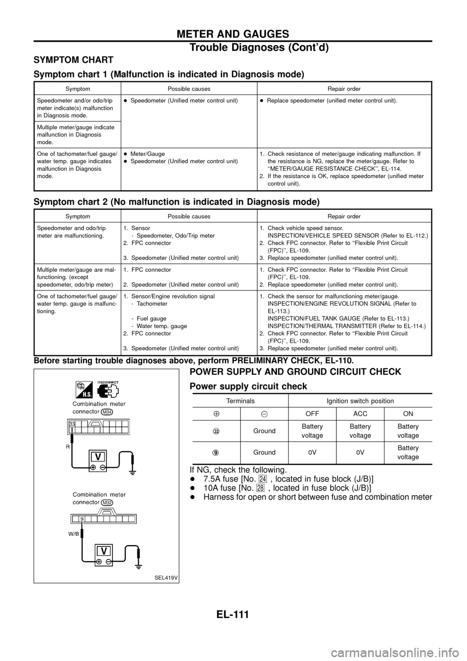
POWER SUPPLY AND GROUND CIRCUIT CHECK
Power supply circuit check
Terminals Ignition switch position
Å@OFF ACC ON
j
33GroundBattery
voltageBattery
voltageBattery
voltage
j
9Ground 0V 0VBattery
voltage
If NG, check the following.
+7.5A fuse [No.
24, located in fuse block (J/B)]
+10A fuse [No.
28, located in fuse block (J/B)]
+Harness for open or short between fuse and combination meter
SEL419V
METER AND GAUGES
Trouble Diagnoses (Cont'd)
EL-111
Page 118 of 326
INSPECTION/THERMAL TRANSMITTER
CHECK THERMAL TRANSMITTER.
Refer to ``THERMAL TRANSMITTER
CHECK'' (EL-115).
OK
cNG
Repair or replace.
CHECK HARNESS FOR OPEN OR
SHORT.
1. Disconnect combination connector and
thermal transmitter connector.
2. Check continuity between combination
meter terminalj
47and thermal transmit-
ter terminalj
1.
Continuity should exist.
3. Check continuity between combination
meter terminalj
47and ground.
Continuity should not exist.
OK
cNG
Repair harness or connec-
tor.
Thermal transmitter is OK.
Electrical Components Inspection
METER/GAUGE RESISTANCE CHECK
1. Disconnect FPC connector. Refer to ``Flexible Print Circuit
(FPC)'' (EL-109).
2. Check resistance between installation screws of meter/gauge.
Screws
Resistance
W
TachometerFuel/Temp.
gaugeSub fuel gauge
A - C A - C Ð Approx. 104 ( 5)
B - D B - C Ð Approx. 134 ( 5)
Ð Ð A - C Approx. 174 ( 5)
Ð Ð B - C Approx. 100 ( 5)
SEL426V
CEL736
.
.
METER AND GAUGES
Trouble Diagnoses (Cont'd)
EL-114
Page 148 of 326
Removal
1. Remove 4 bolts that secure wiper motor.
2. Detach wiper motor from wiper linkage at ball joint.
3. Remove wiper linkage.
Be careful not to break ball joint rubber boot.
Installation
+Grease ball joint portion before installation.
1. Installation is the reverse order of removal.
Washer Nozzle Adjustment
+Adjust washer nozzle with suitable tool as shown in the ®gure
at left.
Adjustable range: 10É
Unit: mm (in)
*1 180 (7.09) *5 70 (2.76)
*2 170 (6.69) *6 40 (1.57)
*3 290 (11.42) *7 370 (14.57)
*4 200 (7.87) *8 470 (18.50)
*: The diameters of these circles are less than 100 mm (3.94 in).
Washer Tube Layout
SEL241P
SEL544T
CEL742
FRONT WIPER AND WASHER
Removal and Installation (Cont'd)
EL-144