1998 NISSAN PATROL Rear wiper
[x] Cancel search: Rear wiperPage 2 of 326
Wiring Diagram Ð H/AIM Ð .....................................71
PARKING, LICENSE AND TAIL LAMPS......................73
Wiring Diagram Ð TAIL/L Ð/Type A .........................73
Wiring Diagram Ð TAIL/L Ð/Type B.........................75
STOP LAMP..................................................................77
Wiring Diagram Ð STOP/L Ð/Type A ......................77
BACK-UP LAMP............................................................78
Wiring Diagram Ð BACK/L Ð/LHD Models..............78
Wiring Diagram Ð BACK/L Ð/RHD Models .............79
REAR FOG LAMP.........................................................80
Wiring Diagram Ð R/FOG Ð ....................................80
TURN SIGNAL AND HAZARD WARNING LAMPS.....81
Wiring Diagram Ð TURN Ð/Type A .........................81
Wiring Diagram Ð TURN Ð/Type B .........................83
Trouble Diagnoses.....................................................85
Electrical Components Inspection .............................85
ILLUMINATION..............................................................86
Schematic ..................................................................86
Wiring Diagram Ð ILL Ð ..........................................87
INTERIOR ROOM LAMP Ð With Timer Ð.................93
System Description ....................................................93
Schematic ..................................................................94
Wiring Diagram Ð ROOM/L Ð/LHD Models ............95
Wiring Diagram Ð ROOM/L Ð/RHD Models............98
Trouble Diagnoses...................................................100
MAP AND VANITY MIRROR LAMPS.........................101
Wiring Diagram Ð INT/L Ð.....................................101
METER AND GAUGES...............................................102
System Description ..................................................102
Combination Meter ..................................................103
Wiring Diagram Ð METER Ð/LHD Models............104
Wiring Diagram Ð METER Ð/RHD Models ...........106
Meter/Gauge Operation and Odo/Trip Meter
Segment Check in Diagnosis Mode ........................108
Flexible Print Circuit (FPC) ......................................109
Trouble Diagnoses................................................... 110
Electrical Components Inspection ........................... 114
COMPASS AND THERMOMETER............................. 116
System Description .................................................. 116
Wiring Diagram Ð COMPAS Ð .............................. 117
Trouble Diagnoses................................................... 118
Calibration Procedure For Compass ....................... 119
WARNING LAMPS......................................................121
Schematic ................................................................121
Wiring Diagram Ð WARN Ð ..................................123
Electrical Components Inspection ...........................134
WARNING CHIME.......................................................135
System Description ..................................................135
Wiring Diagram Ð CHIME Ð/LHD Models.............136
Wiring Diagram Ð CHIME Ð/RHD Models ............137
Trouble Diagnoses...................................................138
Electrical Components Inspection ...........................140FRONT WIPER AND WASHER..................................141
System Description ..................................................141
Wiring Diagram Ð WIPER Ð/With Intermittent
Wiper........................................................................142
Removal and Installation .........................................143
Washer Nozzle Adjustment .....................................144
Washer Tube Layout ...............................................144
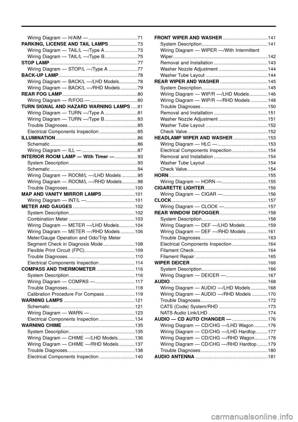
REAR WIPER AND WASHER....................................145
System Description ..................................................145
Wiring Diagram Ð WIP/R Ð/LHD Models ..............146
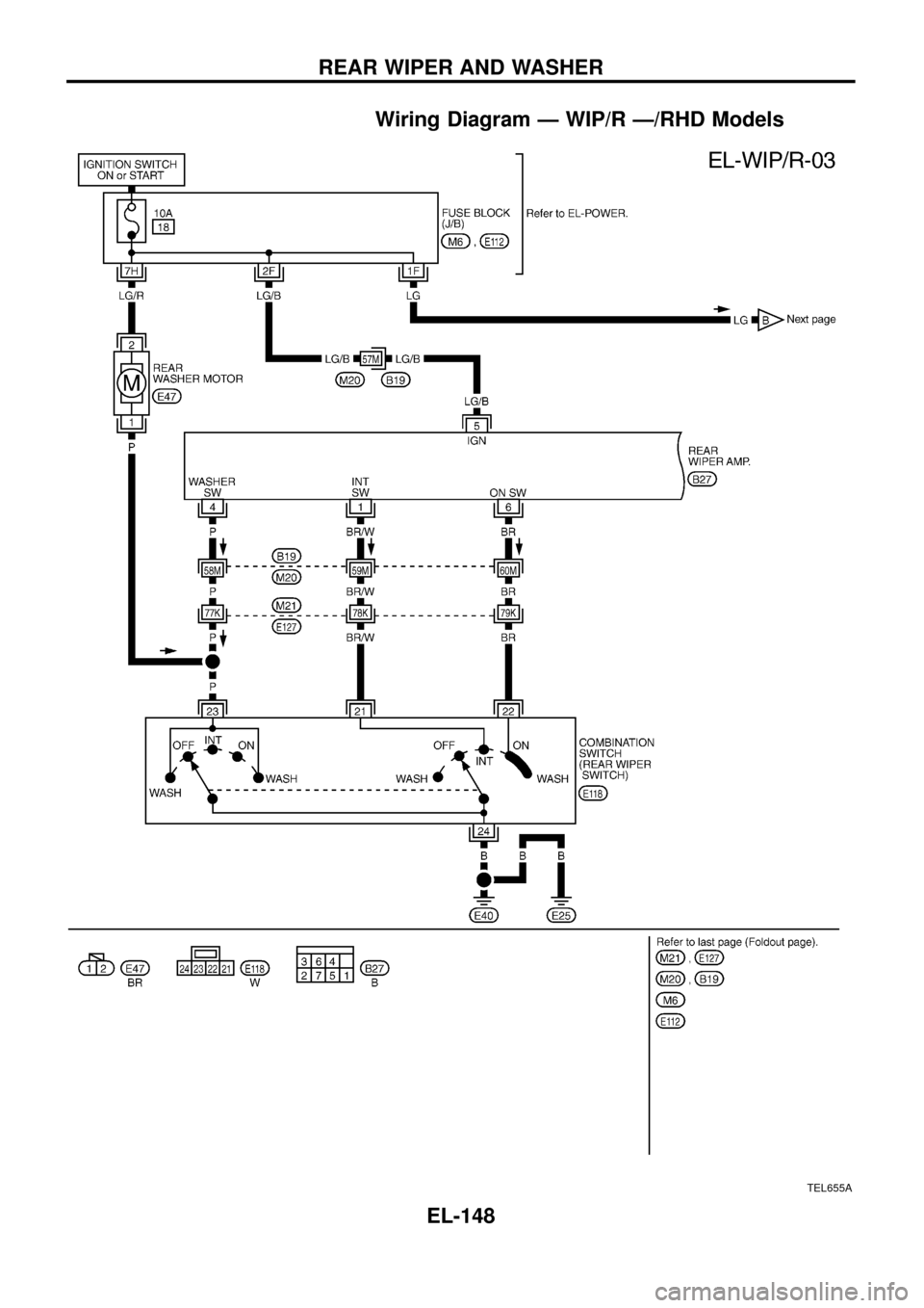
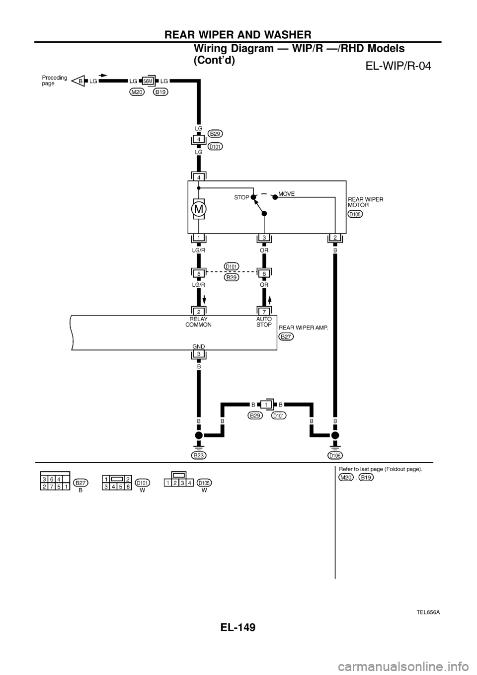
Wiring Diagram Ð WIP/R Ð/RHD Models .............148
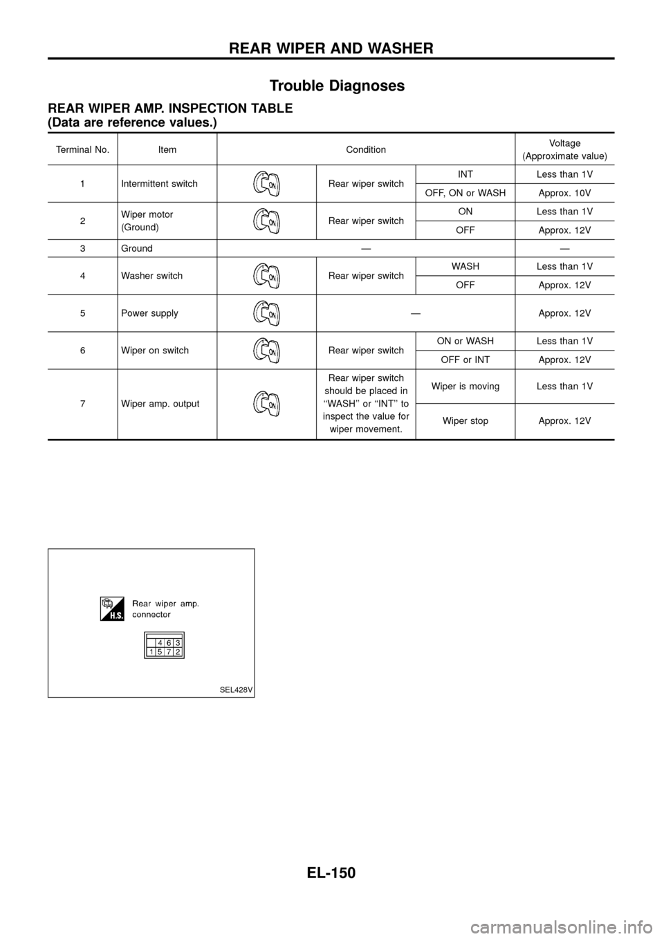
Trouble Diagnoses...................................................150
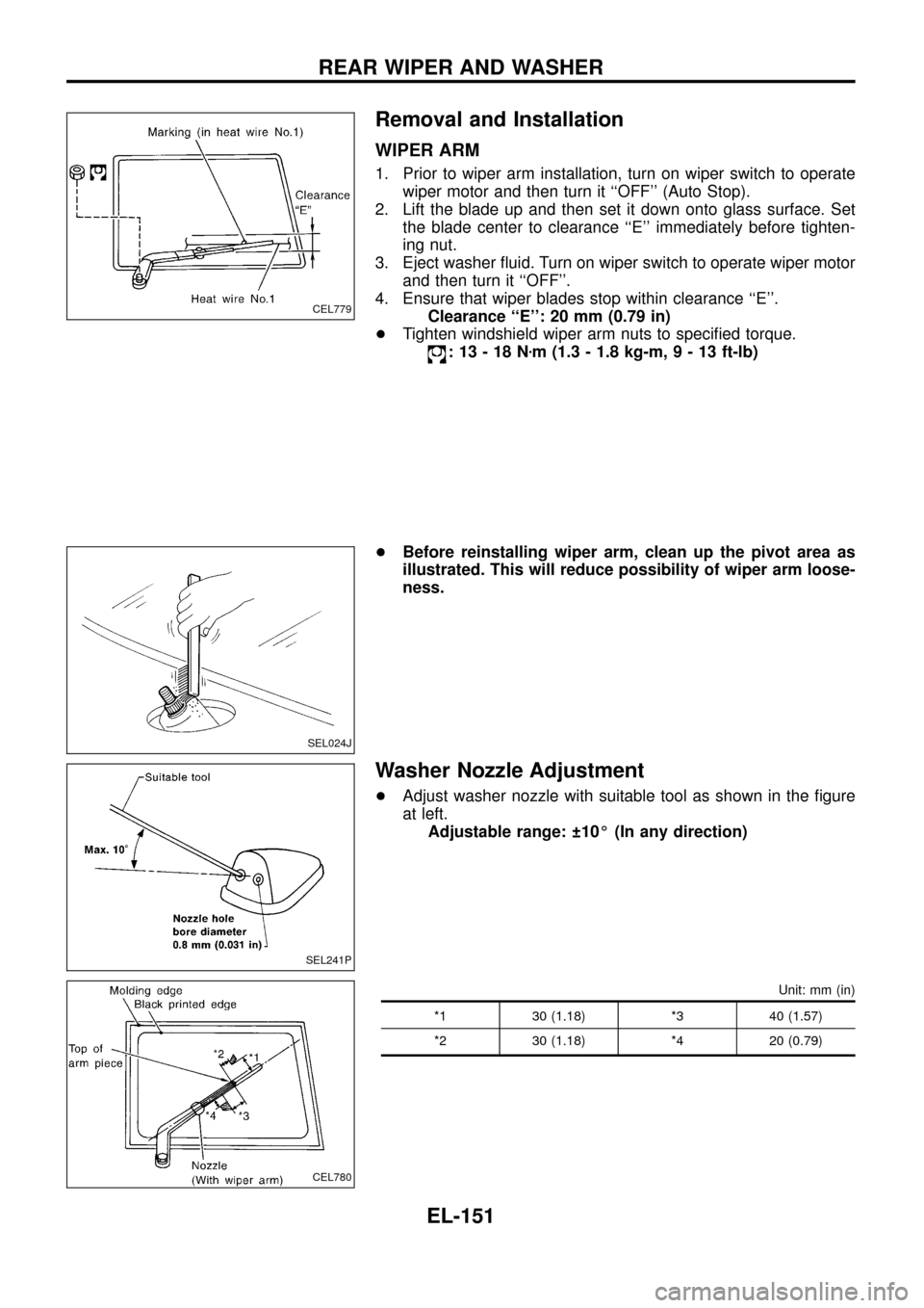
Removal and Installation .........................................151
Washer Nozzle Adjustment .....................................151
Washer Tube Layout ...............................................152
Check Valve .............................................................152
HEADLAMP WIPER AND WASHER..........................153
Wiring Diagram Ð HLC Ð ......................................153
Electrical Components Inspection ...........................154
Removal and Installation .........................................154
Washer Tube Layout ...............................................154
Check Valve .............................................................154
HORN...........................................................................155
Wiring Diagram Ð HORN Ð...................................155
CIGARETTE LIGHTER................................................156
Wiring Diagram Ð CIGAR Ð ..................................156
CLOCK.........................................................................157
Wiring Diagram Ð CLOCK Ð .................................157
REAR WINDOW DEFOGGER.....................................158
System Description ..................................................158
Wiring Diagram Ð DEF Ð/LHD Models .................159
Wiring Diagram Ð DEF Ð/RHD Models ................161
Trouble Diagnoses...................................................163
Electrical Components Inspection ...........................164
Filament Check ........................................................164
Filament Repair .......................................................165
WIPER DEICER...........................................................166
System Description ..................................................166
Wiring Diagram Ð DEICER Ð................................167
AUDIO..........................................................................168
Wiring Diagram Ð AUDIO Ð/LHD Models .............168
Wiring Diagram Ð AUDIO Ð/RHD Models ............170
Trouble Diagnoses...................................................172
CATS (Code) System/RHD .....................................173
NATS Audio Link/LHD .............................................174
AUDIO Ð CD AUTO CHANGER Ð...........................176
Wiring Diagram Ð CD/CHG Ð/LHD Wagon ..........176
Wiring Diagram Ð CD/CHG Ð/LHD Hardtop .........177
Wiring Diagram Ð CD/CHG Ð/RHD Wagon ..........178
Wiring Diagram Ð CD/CHG Ð/RHD Hardtop ........179
Trouble Diagnoses...................................................180
AUDIO ANTENNA.......................................................181
Page 149 of 326
System Description
WIPER OPERATION
The rear wiper switch is controlled by a ring built into the combination switch.
There are two wiper switch positions:
+ON (LO speed)
+INT (Intermittent)
With the ignition switch in the ON position, power is supplied
+through 10A fuse (No.
18, located in the fuse block)
+to rear wiper motor terminalj
4, and
+to rear wiper ampli®er terminalj
5.
Low speed wiper operation
Ground is supplied to rear wiper switch terminalj24through body grounds.
When the rear wiper is placed in the ON position, ground is supplied
+through rear wiper switch terminalj
22
+to rear wiper relay terminalj6.
Then ground is supplied
+to rear wiper motor terminalj
1
+through rear wiper ampli®er terminalsj2andj3.
With power and ground supplied, the wiper motor operates.
Auto stop operation
With the rear wiper switch turned OFF, rear wiper motor will continue to operate until wiper arm reaches rear
window base.
When wiper arm is not located at base of rear window with rear wiper switch OFF, ground is supplied
+to rear wiper motor terminalj
1
+through rear wiper ampli®er terminalsj2,j7and
+through rear wiper motor terminalj
3, in order to continue rear wiper motor operation at low speed.
Ground is also supplied
+to rear wiper motor terminalj
2
+through body grounds.
When wiper arm reaches base of rear window, rear wiper motor terminalsj
3andj4are connected instead
of terminalsj
2andj3. Rear wiper motor will then stop wiper arm at the PARK position.
Intermittent operation
The rear wiper motor operates the wiper arm one time at low speed at an interval of approximately 7 sec-
onds.
When the rear wiper switch is placed in the INT position, ground is supplied
+to rear wiper ampli®er terminalj
1
+through rear wiper switch terminalj21.
Then the rear wiper motor operates intermittently in the same manner as the low speed wiper operation.
WASHER OPERATION
With the ignition switch in the ACC or ON position, power is supplied
+through 10A fuse (No.
18, located in the fuse block)
+to rear washer motor terminalj
2.
When the ring is turned WASH position, ground is supplied
+to rear washer motor terminalj
1, and
+to rear wiper ampli®er terminalj
4
+through terminalj23of rear wiper switch.
With power and ground is supplied, the rear washer motor operates.
The rear wiper motor operates when the ring is turned to WASH position for one second or more and for
approximately 3 seconds after the ring is released. This feature is controlled by the rear wiper ampli®er in the
same manner as the low speed wiper operation.
REAR WIPER AND WASHER
EL-145
Page 150 of 326
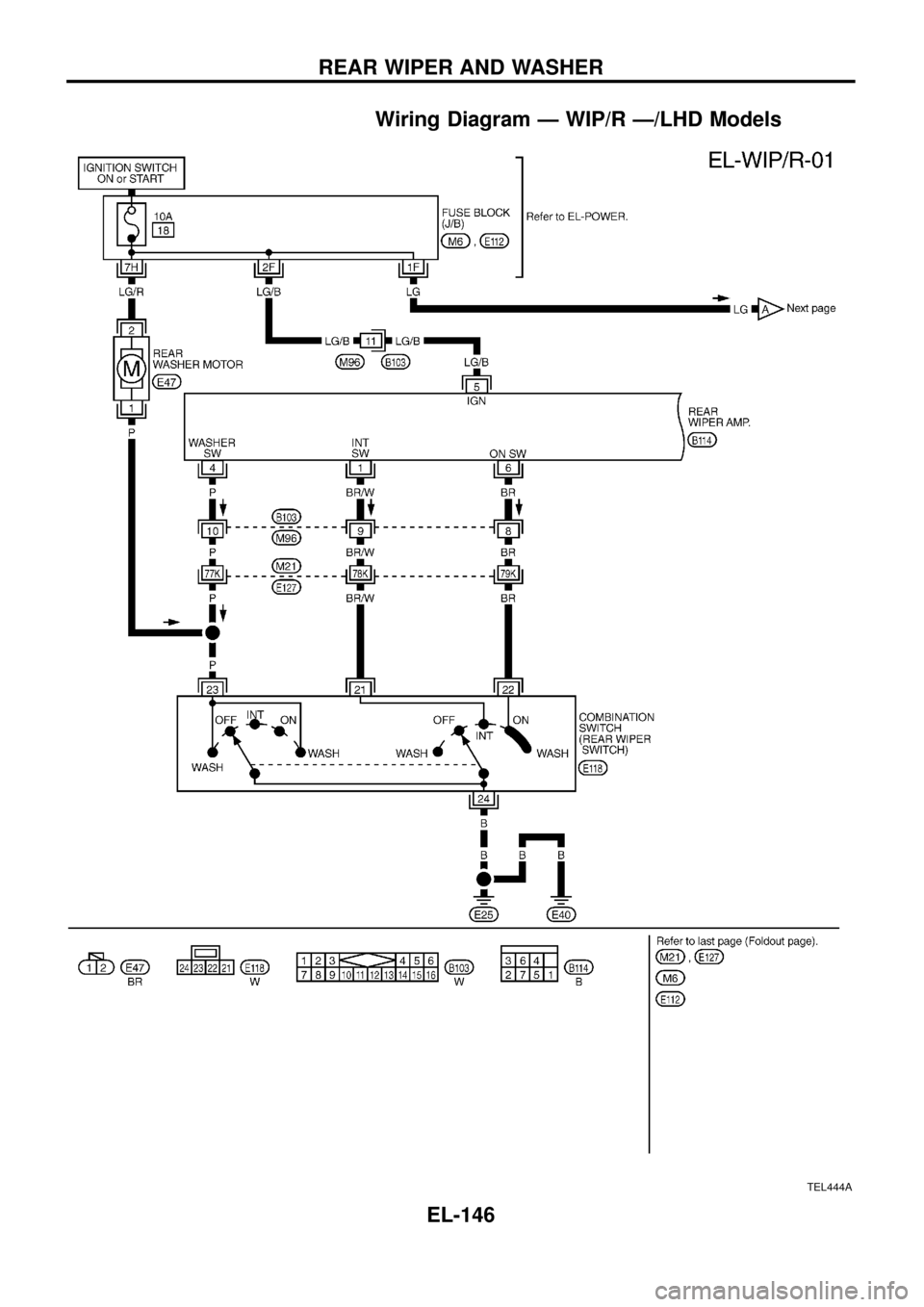
Wiring Diagram Ð WIP/R Ð/LHD Models
TEL444A
REAR WIPER AND WASHER
EL-146
Page 151 of 326
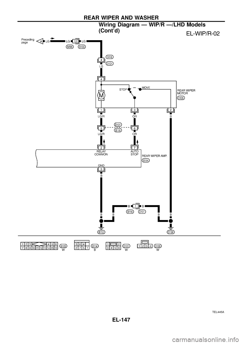
TEL445A
REAR WIPER AND WASHER
Wiring Diagram Ð WIP/R Ð/LHD Models
(Cont'd)
EL-147
Page 152 of 326
Wiring Diagram Ð WIP/R Ð/RHD Models
TEL655A
REAR WIPER AND WASHER
EL-148
Page 153 of 326
TEL656A
REAR WIPER AND WASHER
Wiring Diagram Ð WIP/R Ð/RHD Models
(Cont'd)
EL-149
Page 154 of 326
Trouble Diagnoses
REAR WIPER AMP. INSPECTION TABLE
(Data are reference values.)
Terminal No. Item ConditionVoltage
(Approximate value)
1 Intermittent switch
Rear wiper switchINT Less than 1V
OFF, ON or WASH Approx. 10V
2Wiper motor
(Ground)
Rear wiper switchON Less than 1V
OFF Approx. 12V
3 Ground Ð Ð
4 Washer switch
Rear wiper switchWASH Less than 1V
OFF Approx. 12V
5 Power supply
Ð Approx. 12V
6 Wiper on switch
Rear wiper switchON or WASH Less than 1V
OFF or INT Approx. 12V
7 Wiper amp. output
Rear wiper switch
should be placed in
``WASH'' or ``INT'' to
inspect the value for
wiper movement.Wiper is moving Less than 1V
Wiper stop Approx. 12V
SEL428V
REAR WIPER AND WASHER
EL-150
Page 155 of 326
Removal and Installation
WIPER ARM
1. Prior to wiper arm installation, turn on wiper switch to operate
wiper motor and then turn it ``OFF'' (Auto Stop).
2. Lift the blade up and then set it down onto glass surface. Set
the blade center to clearance ``E'' immediately before tighten-
ing nut.
3. Eject washer ¯uid. Turn on wiper switch to operate wiper motor
and then turn it ``OFF''.
4. Ensure that wiper blades stop within clearance ``E''.
Clearance ``E'': 20 mm (0.79 in)
+Tighten windshield wiper arm nuts to speci®ed torque.
:13-18Nzm (1.3 - 1.8 kg-m,9-13ft-lb)
+Before reinstalling wiper arm, clean up the pivot area as
illustrated. This will reduce possibility of wiper arm loose-
ness.
Washer Nozzle Adjustment
+Adjust washer nozzle with suitable tool as shown in the ®gure
at left.
Adjustable range: 10É (In any direction)
Unit: mm (in)
*1 30 (1.18) *3 40 (1.57)
*2 30 (1.18) *4 20 (0.79)
CEL779
SEL024J
SEL241P
CEL780
REAR WIPER AND WASHER
EL-151