1998 NISSAN PATROL Light switch
[x] Cancel search: Light switchPage 1 of 326
ELECTRICAL SYSTEM
SECTION
EL
When you read wiring diagrams:
+Read GI section, ``HOW TO READ WIRING DIAGRAMS''.
When you perform trouble diagnoses, read GI section, ``HOW TO FOLLOW FLOW
CHART IN TROUBLE DIAGNOSES'' and ``HOW TO PERFORM EFFICIENT DIAGNOSIS
FOR AN ELECTRICAL INCIDENT''.
+Check for any service bulletins before servicing the vehicle.
CONTENTS
PRECAUTIONS...............................................................1
Supplemental Restraint System (SRS) ``AIR
BAG'' and ``SEAT BELT PRE-TENSIONER''...............1
HARNESS CONNECTOR................................................2
Description ...................................................................2
STANDARDIZED RELAY................................................3
Description ...................................................................3
POWER SUPPLY ROUTING...........................................5
Schematic ....................................................................5
Wiring Diagram Ð POWER Ð....................................6
Fuse ...........................................................................14
Fusible Link................................................................14
Circuit Breaker Inspection .........................................14
GROUND DISTRIBUTION/LHD MODELS....................15
Engine Room Harness ..............................................15
Main Harness.............................................................19
Body Harness ............................................................22
Body No. 2 Harness ..................................................23
Back Door and Rear Window Defogger Harness .....24
Room Lamp Harness.................................................25
GROUND DISTRIBUTION/RHD MODELS...................26
Engine Room Harness ..............................................26
Main Harness.............................................................30
Body Harness ............................................................33
Body No. 2 Harness ..................................................34
Back Door and Rear Window Defogger Harness .....35
Room Lamp Harness.................................................36
BATTERY.......................................................................37
How to Handle Battery ..............................................37
Battery Test and Charging Chart ...............................40
Service Data and Speci®cations (SDS).....................44
STARTING SYSTEM.....................................................45
Wiring Diagram Ð START Ð ....................................45Trouble Diagnoses.....................................................46
Construction ...............................................................47
Removal and Installation ...........................................47
Inspection...................................................................47
Assembly ...................................................................50
Service Data and Speci®cations (SDS).....................51
CHARGING SYSTEM....................................................52
Wiring Diagram Ð CHARGE Ð ................................52
Trouble Diagnoses.....................................................53
Construction ...............................................................54
Removal and Installation ...........................................54
Disassembly...............................................................54
Inspection...................................................................55
Assembly ...................................................................56
Service Data and Speci®cations (SDS).....................56
COMBINATION SWITCH...............................................57
Check .........................................................................57
Replacement ..............................................................58
STEERING SWITCH......................................................59
Check .........................................................................59
HEADLAMP Ð Conventional Type Ð........................61
Wiring Diagram Ð H/LAMP Ð ..................................61
Trouble Diagnoses.....................................................62
Bulb Replacement .....................................................63
Aiming Adjustment .....................................................63
HEADLAMP Ð Daytime Light System Ð..................65
System Description ....................................................65
Wiring Diagram Ð DTRL Ð ......................................67
Trouble Diagnoses.....................................................69
Bulb Replacement .....................................................69
Aiming Adjustment .....................................................69
HEADLAMP Ð Headlamp Aiming Control Ð............70
System Description ....................................................70
EL
Page 66 of 326
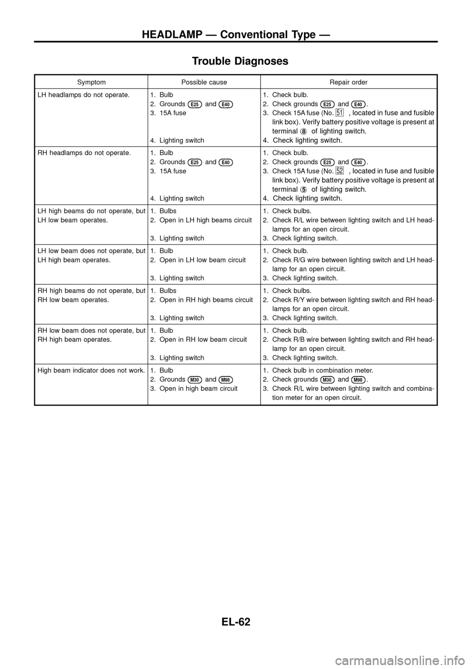
Trouble Diagnoses
Symptom Possible cause Repair order
LH headlamps do not operate. 1. Bulb
2. Grounds
E25andE40
3. 15A fuse
4. Lighting switch1. Check bulb.
2. Check grounds
E25andE40.
3. Check 15A fuse (No.
51, located in fuse and fusible
link box). Verify battery positive voltage is present at
terminalj
8of lighting switch.
4. Check lighting switch.
RH headlamps do not operate. 1. Bulb
2. Grounds
E25andE40
3. 15A fuse
4. Lighting switch1. Check bulb.
2. Check grounds
E25andE40.
3. Check 15A fuse (No.
52, located in fuse and fusible
link box). Verify battery positive voltage is present at
terminalj
5of lighting switch.
4. Check lighting switch.
LH high beams do not operate, but
LH low beam operates.1. Bulbs
2. Open in LH high beams circuit
3. Lighting switch1. Check bulbs.
2. Check R/L wire between lighting switch and LH head-
lamps for an open circuit.
3. Check lighting switch.
LH low beam does not operate, but
LH high beam operates.1. Bulb
2. Open in LH low beam circuit
3. Lighting switch1. Check bulb.
2. Check R/G wire between lighting switch and LH head-
lamp for an open circuit.
3. Check lighting switch.
RH high beams do not operate, but
RH low beam operates.1. Bulbs
2. Open in RH high beams circuit
3. Lighting switch1. Check bulbs.
2. Check R/Y wire between lighting switch and RH head-
lamps for an open circuit.
3. Check lighting switch.
RH low beam does not operate, but
RH high beam operates.1. Bulb
2. Open in RH low beam circuit
3. Lighting switch1. Check bulb.
2. Check R/B wire between lighting switch and RH head-
lamp for an open circuit.
3. Check lighting switch.
High beam indicator does not work. 1. Bulb
2. Grounds
M30andM98
3. Open in high beam circuit1. Check bulb in combination meter.
2. Check grounds
M30andM98.
3. Check R/L wire between lighting switch and combina-
tion meter for an open circuit.
HEADLAMP Ð Conventional Type Ð
EL-62
Page 69 of 326
System Description
OPERATION
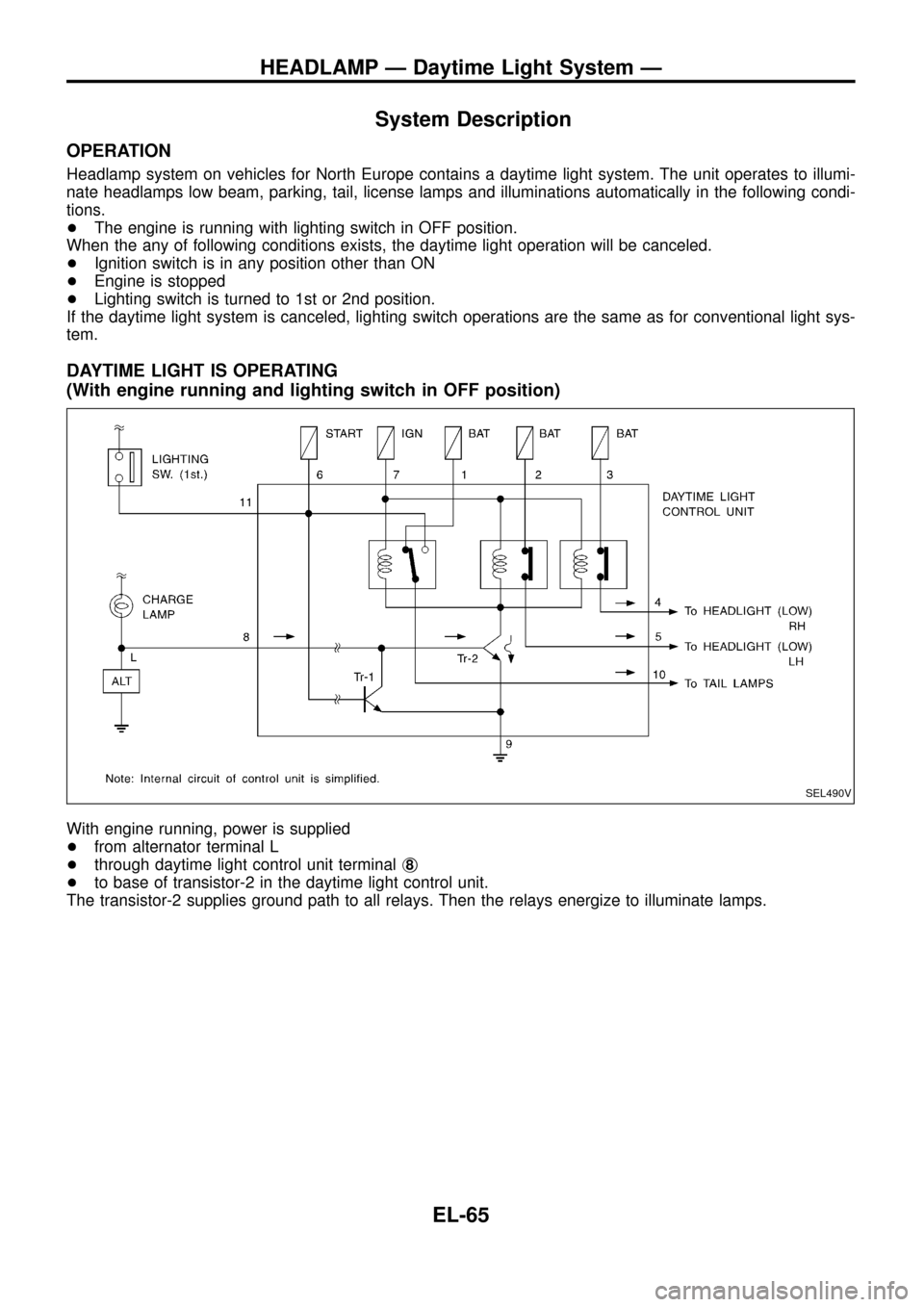
Headlamp system on vehicles for North Europe contains a daytime light system. The unit operates to illumi-
nate headlamps low beam, parking, tail, license lamps and illuminations automatically in the following condi-
tions.
+The engine is running with lighting switch in OFF position.
When the any of following conditions exists, the daytime light operation will be canceled.
+Ignition switch is in any position other than ON
+Engine is stopped
+Lighting switch is turned to 1st or 2nd position.
If the daytime light system is canceled, lighting switch operations are the same as for conventional light sys-
tem.
DAYTIME LIGHT IS OPERATING
(With engine running and lighting switch in OFF position)
With engine running, power is supplied
+from alternator terminal L
+through daytime light control unit terminalj
8
+to base of transistor-2 in the daytime light control unit.
The transistor-2 supplies ground path to all relays. Then the relays energize to illuminate lamps.
SEL490V
HEADLAMP Ð Daytime Light System Ð
EL-65
Page 70 of 326
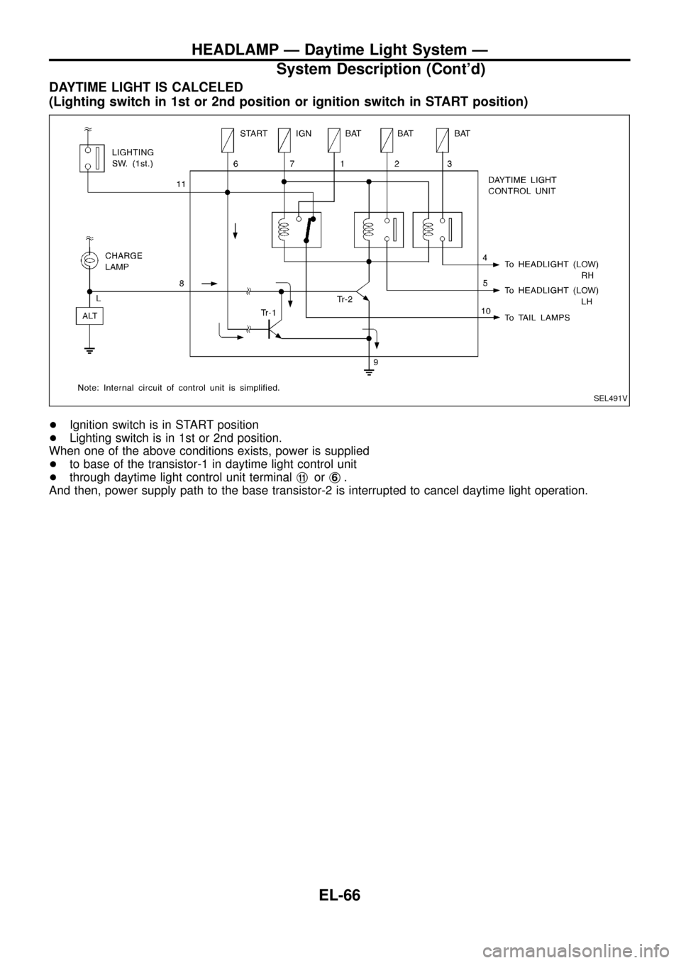
DAYTIME LIGHT IS CALCELED
(Lighting switch in 1st or 2nd position or ignition switch in START position)
+Ignition switch is in START position
+Lighting switch is in 1st or 2nd position.
When one of the above conditions exists, power is supplied
+to base of the transistor-1 in daytime light control unit
+through daytime light control unit terminalj
11orj6.
And then, power supply path to the base transistor-2 is interrupted to cancel daytime light operation.
SEL491V
HEADLAMP Ð Daytime Light System Ð
System Description (Cont'd)
EL-66
Page 73 of 326
Trouble Diagnoses
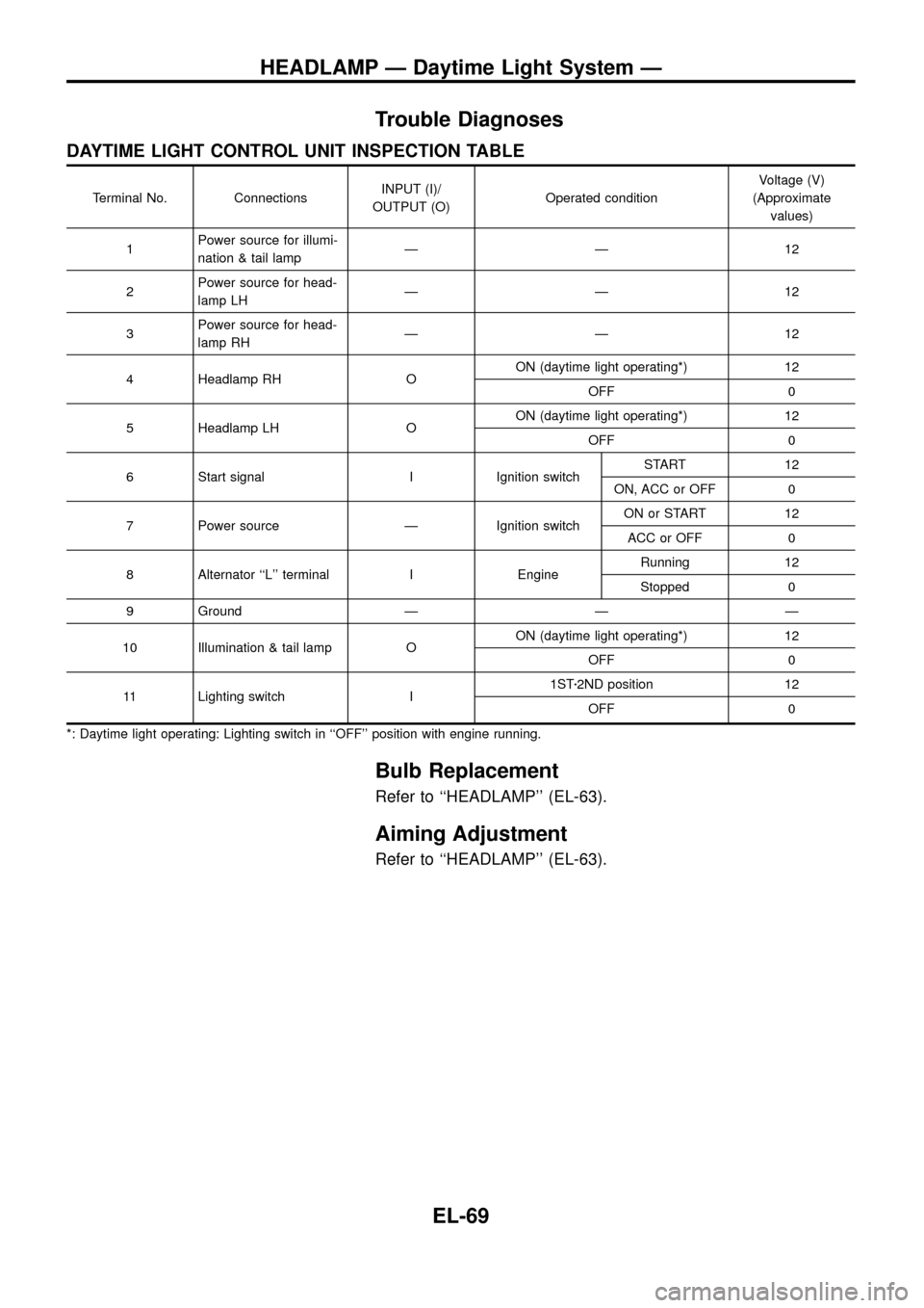
DAYTIME LIGHT CONTROL UNIT INSPECTION TABLE
Terminal No. ConnectionsINPUT (I)/
OUTPUT (O)Operated conditionVoltage (V)
(Approximate
values)
1Power source for illumi-
nation & tail lampÐÐ12
2Power source for head-
lamp LHÐÐ12
3Power source for head-
lamp RHÐÐ12
4 Headlamp RH OON (daytime light operating*) 12
OFF 0
5 Headlamp LH OON (daytime light operating*) 12
OFF 0
6 Start signal I Ignition switchSTART 12
ON, ACC or OFF 0
7 Power source Ð Ignition switchON or START 12
ACC or OFF 0
8 Alternator ``L'' terminal I EngineRunning 12
Stopped 0
9 Ground Ð Ð Ð
10 Illumination & tail lamp OON (daytime light operating*) 12
OFF 0
11 Lighting switch I1STz2ND position 12
OFF 0
*: Daytime light operating: Lighting switch in ``OFF'' position with engine running.
Bulb Replacement
Refer to ``HEADLAMP'' (EL-63).
Aiming Adjustment
Refer to ``HEADLAMP'' (EL-63).
HEADLAMP Ð Daytime Light System Ð
EL-69
Page 138 of 326
Electrical Components Inspection
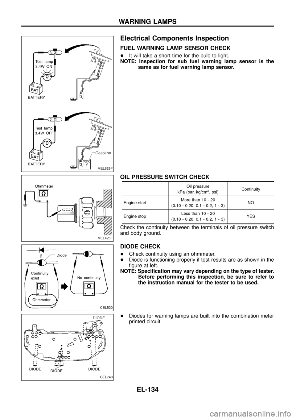
FUEL WARNING LAMP SENSOR CHECK
+It will take a short time for the bulb to light.
NOTE: Inspection for sub fuel warning lamp sensor is the
same as for fuel warning lamp sensor.
OIL PRESSURE SWITCH CHECK
Oil pressure
kPa (bar, kg/cm2, psi)Continuity
Engine startMore than 10 - 20
(0.10 - 0.20, 0.1 - 0.2,1-3)NO
Engine stopLess than 10 - 20
(0.10 - 0.20, 0.1 - 0.2,1-3)YES
Check the continuity between the terminals of oil pressure switch
and body ground.
DIODE CHECK
+Check continuity using an ohmmeter.
+Diode is functioning properly if test results are as shown in the
®gure at left.
NOTE: Speci®cation may vary depending on the type of tester.
Before performing this inspection, be sure to refer to
the instruction manual for the tester to be used.
+Diodes for warning lamps are built into the combination meter
printed circuit.
MEL828F
MEL425F
CEL520
CEL740
WARNING LAMPS
EL-134
Page 139 of 326
System Description
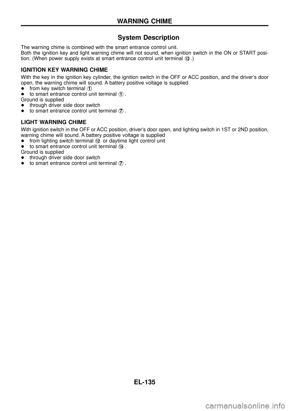
The warning chime is combined with the smart entrance control unit.
Both the ignition key and light warning chime will not sound, when ignition switch in the ON or START posi-
tion. (When power supply exists at smart entrance control unit terminalj
12.)
IGNITION KEY WARNING CHIME
With the key in the ignition key cylinder, the ignition switch in the OFF or ACC position, and the driver's door
open, the warning chime will sound. A battery positive voltage is supplied
+from key switch terminalj
1
+to smart entrance control unit terminalj1.
Ground is supplied
+through driver side door switch
+to smart entrance control unit terminalj
7.
LIGHT WARNING CHIME
With ignition switch in the OFF or ACC position, driver's door open, and lighting switch in 1ST or 2ND position,
warning chime will sound. A battery positive voltage is supplied
+from lighting switch terminalj
12or daytime light control unit
+to smart entrance control unit terminalj
14.
Ground is supplied
+through driver side door switch
+to smart entrance control unit terminalj
7.
WARNING CHIME
EL-135
Page 142 of 326
Trouble Diagnoses
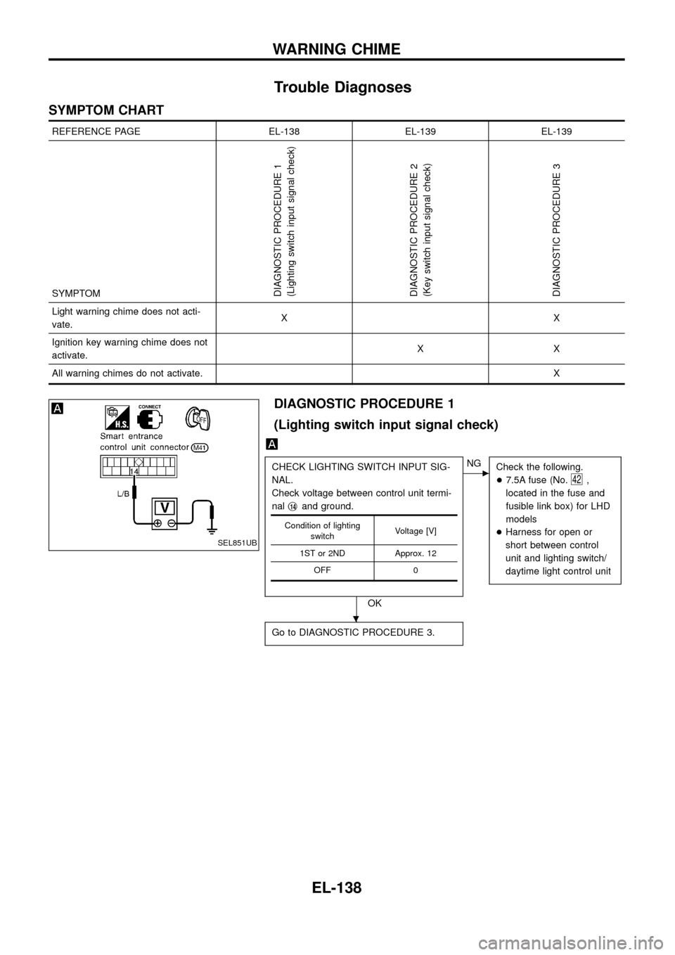
SYMPTOM CHART
REFERENCE PAGE EL-138 EL-139 EL-139
SYMPTOM
DIAGNOSTIC PROCEDURE 1
(Lighting switch input signal check)
DIAGNOSTIC PROCEDURE 2
(Key switch input signal check)
DIAGNOSTIC PROCEDURE 3
Light warning chime does not acti-
vate.XX
Ignition key warning chime does not
activate.XX
All warning chimes do not activate.X
DIAGNOSTIC PROCEDURE 1
(Lighting switch input signal check)
CHECK LIGHTING SWITCH INPUT SIG-
NAL.
Check voltage between control unit termi-
nalj
14and ground.
OK
cNG
Check the following.
+7.5A fuse (No.
42,
located in the fuse and
fusible link box) for LHD
models
+Harness for open or
short between control
unit and lighting switch/
daytime light control unit
Go to DIAGNOSTIC PROCEDURE 3.
Condition of lighting
switchVoltage [V]
1ST or 2ND Approx. 12
OFF 0
SEL851UB
.
WARNING CHIME
EL-138