SYMPTOM CHART
Symptom chart 1 (Malfunction is indicated in Diagnosis mode)
Symptom Possible causes Repair order
Speedometer and/or odo/trip
meter indicate(s) malfunction
in Diagnosis mode.+Speedometer (Uni®ed meter control unit)+Replace speedometer (uni®ed meter control unit).
Multiple meter/gauge indicate
malfunction in Diagnosis
mode.
One of tachometer/fuel gauge/
water temp. gauge indicates
malfunction in Diagnosis
mode.+Meter/Gauge
+Speedometer (Uni®ed meter control unit)1. Check resistance of meter/gauge indicating malfunction. If
the resistance is NG, replace the meter/gauge. Refer to
``METER/GAUGE RESISTANCE CHECK'', EL-114.
2. If the resistance is OK, replace speedometer (uni®ed meter
control unit).
Symptom chart 2 (No malfunction is indicated in Diagnosis mode)
Symptom Possible causes Repair order
Speedometer and odo/trip
meter are malfunctioning.1. Sensor
- Speedometer, Odo/Trip meter
2. FPC connector
3. Speedometer (Uni®ed meter control unit)1. Check vehicle speed sensor.
INSPECTION/VEHICLE SPEED SENSOR (Refer to EL-112.)
2. Check FPC connector. Refer to ``Flexible Print Circuit
(FPC)'', EL-109.
3. Replace speedometer (uni®ed meter control unit).
Multiple meter/gauge are mal-
functioning. (except
speedometer, odo/trip meter)1. FPC connector
2. Speedometer (Uni®ed meter control unit)1. Check FPC connector. Refer to ``Flexible Print Circuit
(FPC)'', EL-109.
2. Replace speedometer (uni®ed meter control unit).
One of tachometer/fuel gauge/
water temp. gauge is malfunc-
tioning.1. Sensor/Engine revolution signal
- Tachometer
- Fuel gauge
- Water temp. gauge
2. FPC connector
3. Speedometer (Uni®ed meter control unit)1. Check the sensor for malfunctioning meter/gauge.
INSPECTION/ENGINE REVOLUTION SIGNAL (Refer to
EL-113.)
INSPECTION/FUEL TANK GAUGE (Refer to EL-113.)
INSPECTION/THERMAL TRANSMITTER (Refer to EL-114.)
2. Check FPC connector. Refer to ``Flexible Print Circuit
(FPC)'', EL-109.
3. Replace speedometer (uni®ed meter control unit).
Before starting trouble diagnoses above, perform PRELIMINARY CHECK, EL-110.
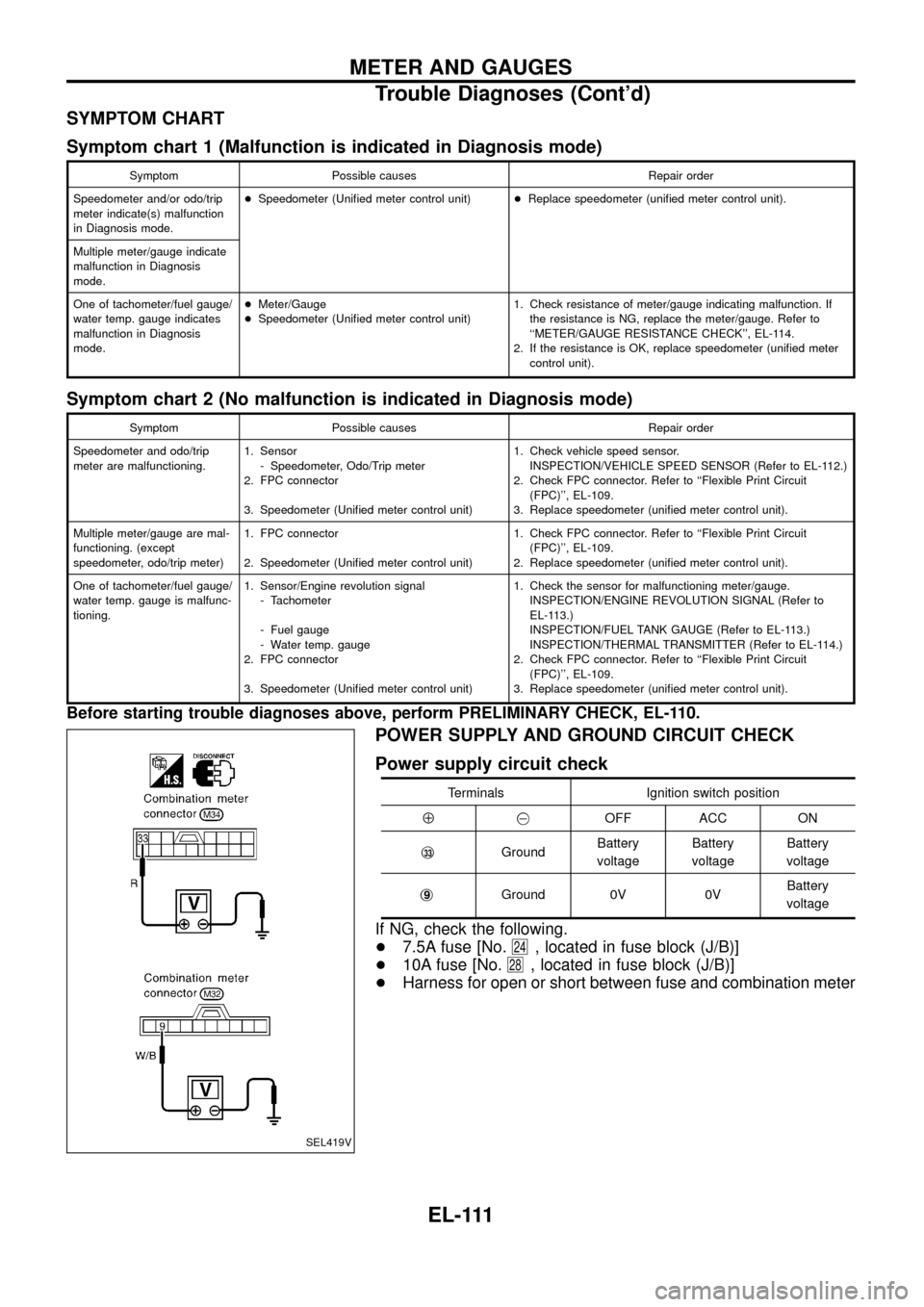
POWER SUPPLY AND GROUND CIRCUIT CHECK
Power supply circuit check
Terminals Ignition switch position
Å@OFF ACC ON
j
33GroundBattery
voltageBattery
voltageBattery
voltage
j
9Ground 0V 0VBattery
voltage
If NG, check the following.
+7.5A fuse [No.
24, located in fuse block (J/B)]
+10A fuse [No.
28, located in fuse block (J/B)]
+Harness for open or short between fuse and combination meter
SEL419V
METER AND GAUGES
Trouble Diagnoses (Cont'd)
EL-111
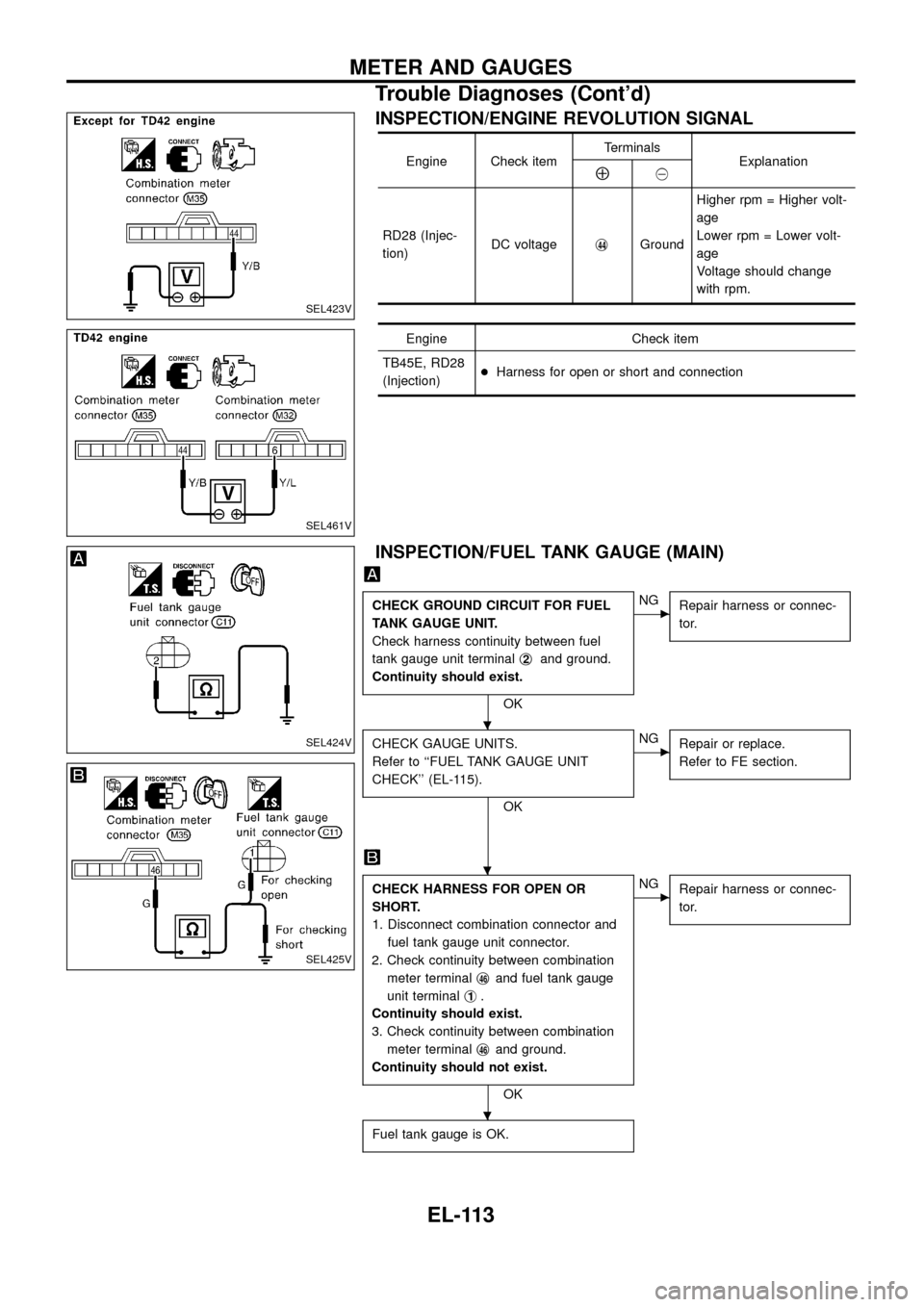
INSPECTION/ENGINE REVOLUTION SIGNAL
Engine Check itemTerminals
ExplanationÅ@
RD28 (Injec-
tion)DC voltagej
44GroundHigher rpm = Higher volt-
age
Lower rpm = Lower volt-
age
Voltage should change
with rpm.
Engine Check item
TB45E, RD28
(Injection)+Harness for open or short and connection
INSPECTION/FUEL TANK GAUGE (MAIN)
CHECK GROUND CIRCUIT FOR FUEL
TANK GAUGE UNIT.
Check harness continuity between fuel
tank gauge unit terminalj
2and ground.
Continuity should exist.
OK
cNG
Repair harness or connec-
tor.
CHECK GAUGE UNITS.
Refer to ``FUEL TANK GAUGE UNIT
CHECK'' (EL-115).
OK
cNG
Repair or replace.
Refer to FE section.
CHECK HARNESS FOR OPEN OR
SHORT.
1. Disconnect combination connector and
fuel tank gauge unit connector.
2. Check continuity between combination
meter terminalj
46and fuel tank gauge
unit terminalj
1.
Continuity should exist.
3. Check continuity between combination
meter terminalj
46and ground.
Continuity should not exist.
OK
cNG
Repair harness or connec-
tor.
Fuel tank gauge is OK.
SEL423V
SEL461V
SEL424V
SEL425V
.
.
.
METER AND GAUGES
Trouble Diagnoses (Cont'd)
EL-113