1998 NISSAN PATROL power supply
[x] Cancel search: power supplyPage 154 of 326
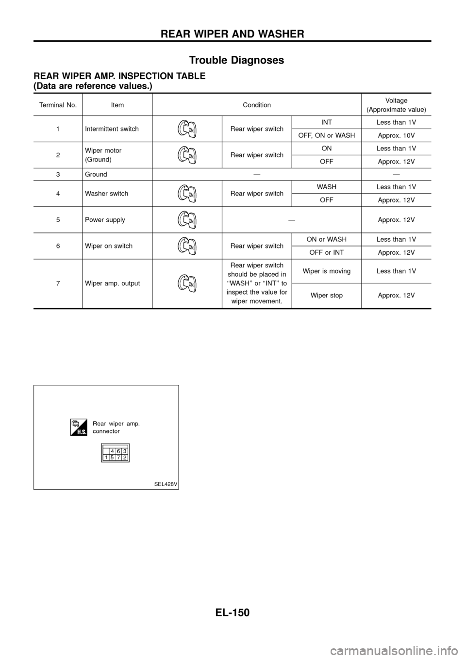
Trouble Diagnoses
REAR WIPER AMP. INSPECTION TABLE
(Data are reference values.)
Terminal No. Item ConditionVoltage
(Approximate value)
1 Intermittent switch
Rear wiper switchINT Less than 1V
OFF, ON or WASH Approx. 10V
2Wiper motor
(Ground)
Rear wiper switchON Less than 1V
OFF Approx. 12V
3 Ground Ð Ð
4 Washer switch
Rear wiper switchWASH Less than 1V
OFF Approx. 12V
5 Power supply
Ð Approx. 12V
6 Wiper on switch
Rear wiper switchON or WASH Less than 1V
OFF or INT Approx. 12V
7 Wiper amp. output
Rear wiper switch
should be placed in
``WASH'' or ``INT'' to
inspect the value for
wiper movement.Wiper is moving Less than 1V
Wiper stop Approx. 12V
SEL428V
REAR WIPER AND WASHER
EL-150
Page 177 of 326
CATS (Code) System/RHD
NOTE:
+This system is used for code indicator-equipped radios on all models except the Europe LHD
model.
+The Europe LHD model has a NATS-linked anti-theft function that renders the code system inop-
erable.
DESCRIPTION
By using a personal 4-digit code known only to the vehicle owner, the possibility of the audio unit being sto-
len is effectively reduced, because without the code the unit can not be activated. When in normal use, the
unit is unlocked and accessible in the usual way.
If however, someone attempts to remove the unit or the battery cable is disconnected, the anti-theft system
activates and the unit ``locks''. The only way it can be unlocked is by entering a personal code number known
only by the owner.
UNLOCKING THE UNIT (How to enter a personal code number)
+If the battery supply to the vehicle is interrupted by accident for some reason, the unit will lock.
To unlock the unit, proceed as follows:
1. Press the power/volume control knob to turn the unit on.
2. ``CODE IN'' is displayed.
3. Input your personal code by pressing the preset buttons (1 to 4).
4. Press the
button.
5. If the entered code number is correct, the radio turns on.
When the code is incorrect
1. If the entered code is incorrect, the unit becomes inoperable for 10 seconds for the ®rst three attempts,
then the code input mode is automatically set (``CODE IN'' is displayed).
2. If the code is incorrect the fourth time, the unit becomes inoperable for 60 minutes and ``
'' is displayed.
After 60 minutes, the code input mode is automatically set (``CODE IN'' is displayed).
NOTE:
If the above is repeated 17 times, the unit will lock and ``LOCKED'' is displayed.
3. After ``LOCKED'' is displayed, radio can be returned to the code input mode only within three attempts as
follows. (Only three attempts are allowed to unlock the unit.)
a. Press the power/volume control knob while pushing both the MOD and TA switches.
b. The unit then returns to the code input mode.
CAUTION:
If the third attempt is unsuccessful, the unit will lock permanently.
AUDIO
EL-173
Page 211 of 326
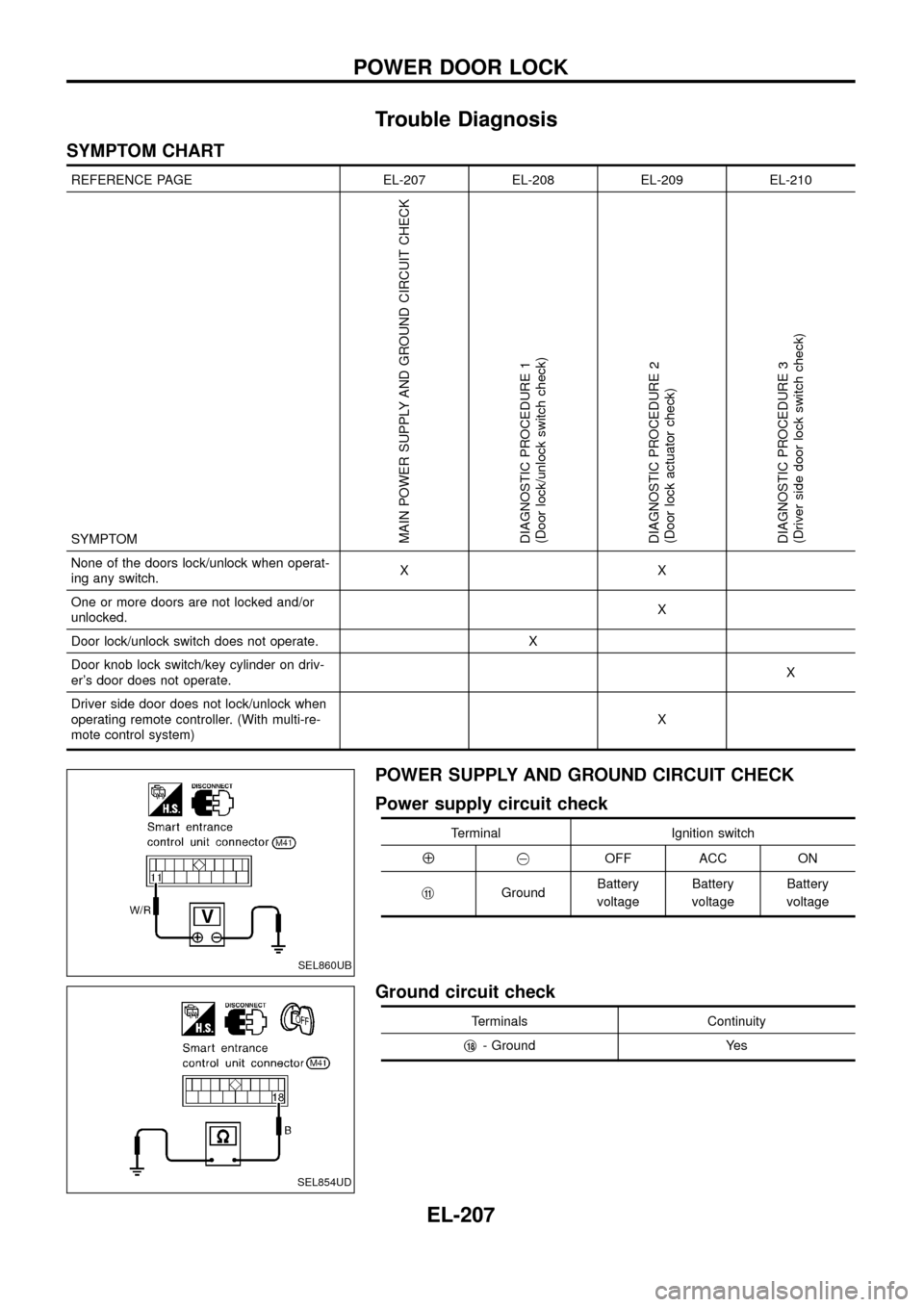
Trouble Diagnosis
SYMPTOM CHART
REFERENCE PAGE EL-207 EL-208 EL-209 EL-210
SYMPTOM
MAIN POWER SUPPLY AND GROUND CIRCUIT CHECK
DIAGNOSTIC PROCEDURE 1
(Door lock/unlock switch check)
DIAGNOSTIC PROCEDURE 2
(Door lock actuator check)
DIAGNOSTIC PROCEDURE 3
(Driver side door lock switch check)
None of the doors lock/unlock when operat-
ing any switch.XX
One or more doors are not locked and/or
unlocked.X
Door lock/unlock switch does not operate. X
Door knob lock switch/key cylinder on driv-
er's door does not operate.X
Driver side door does not lock/unlock when
operating remote controller. (With multi-re-
mote control system)X
POWER SUPPLY AND GROUND CIRCUIT CHECK
Power supply circuit check
Terminal Ignition switch
Å@OFF ACC ON
j
11GroundBattery
voltageBattery
voltageBattery
voltage
Ground circuit check
Terminals Continuity
j
18- Ground Yes
SEL860UB
SEL854UD
POWER DOOR LOCK
EL-207
Page 228 of 326
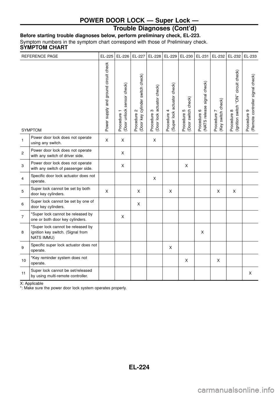
Before starting trouble diagnoses below, perform preliminary check, EL-223.
Symptom numbers in the symptom chart correspond with those of Preliminary check.
SYMPTOM CHART
REFERENCE PAGE EL-225 EL-226 EL-227 EL-228 EL-229 EL-230 EL-231 EL-232 EL-232 EL-233
SYMPTOM
Power supply and ground circuit check
Procedure 1
(Door unlock sensor check)
Procedure 2
(Door key cylinder switch check)
Procedure 3
(Door lock actuator check)
Procedure 4
(Super lock actuator check)
Procedure 5
(Door switch check)
Procedure 6
(NATS release signal check)
Procedure 7
(Key switch check)
Procedure 8
(Ignition switch ``ON'' circuit check)
Procedure 9
(Remote controller signal check)
1Power door lock does not operate
using any switch.XX X
2Power door lock does not operate
with any switch of driver side.X
3Power door lock does not operate
with any switch of passenger side.XX
4Speci®c door lock actuator does not
operate.X
5Super lock cannot be set by both
door key cylinders.XXX XX
6Super lock cannot be set by one of
door key cylinders.X
7*Super lock cannot be released by
one or both door key cylinders.X
8*Super lock cannot be released by
ignition key switch. (Signal from
NATS IMMU)X
9Speci®c super lock actuator does not
operate.X
10*Key reminder system does not
operate.XX
11Super lock cannot be set/released
by using multi-remote controller.X
X: Applicable
*: Make sure the power door lock system operates properly.
POWER DOOR LOCK Ð Super Lock Ð
Trouble Diagnoses (Cont'd)
EL-224
Page 229 of 326
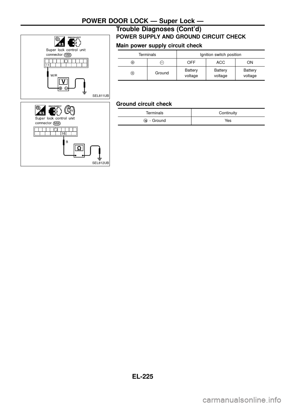
POWER SUPPLY AND GROUND CIRCUIT CHECK
Main power supply circuit check
Terminals Ignition switch position
Å@OFF ACC ON
j
11GroundBattery
voltageBattery
voltageBattery
voltage
Ground circuit check
Terminals Continuity
j
16- Ground Yes
SEL811UB
SEL812UB
POWER DOOR LOCK Ð Super Lock Ð
Trouble Diagnoses (Cont'd)
EL-225
Page 236 of 326
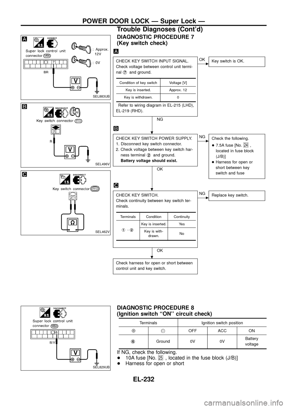
DIAGNOSTIC PROCEDURE 7
(Key switch check)
CHECK KEY SWITCH INPUT SIGNAL.
Check voltage between control unit termi-
nalj
7and ground.
Refer to wiring diagram in EL-215 (LHD),
EL-219 (RHD).
NG
cOK
Key switch is OK.
CHECK KEY SWITCH POWER SUPPLY.
1. Disconnect key switch connector.
2. Check voltage between key switch har-
ness terminalj
2and ground.
Battery voltage should exist.
OK
cNG
Check the following.
+7.5A fuse [No.
24,
located in fuse block
(J/B)]
+Harness for open or
short between key
switch and fuse
CHECK KEY SWITCH.
Check continuity between key switch ter-
minals.
OK
cNG
Replace key switch.
Check harness for open or short between
control unit and key switch.
Condition of key switch Voltage [V]
Key is inserted. Approx. 12
Key is withdrawn. 0
Terminals Condition Continuity
j
1-j2
Key is inserted. Yes
Key is with-
drawn.No
DIAGNOSTIC PROCEDURE 8
(Ignition switch ``ON'' circuit check)
Terminals Ignition switch position
Å@OFF ACC ON
j
6Ground 0V 0VBattery
voltage
If NG, check the following.
+10A fuse [No.
25, located in the fuse block (J/B)]
+Harness for open or short
SEL883UB
SEL496V
SEL462V
SEL829UB
.
.
.
POWER DOOR LOCK Ð Super Lock Ð
Trouble Diagnoses (Cont'd)
EL-232
Page 238 of 326
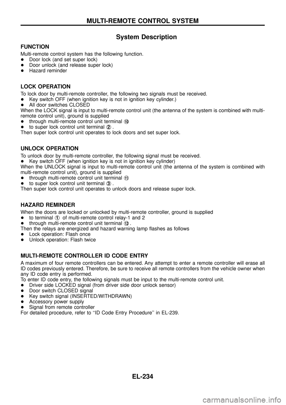
System Description
FUNCTION
Multi-remote control system has the following function.
+Door lock (and set super lock)
+Door unlock (and release super lock)
+Hazard reminder
LOCK OPERATION
To lock door by multi-remote controller, the following two signals must be received.
+Key switch OFF (when ignition key is not in ignition key cylinder.)
+All door switches CLOSED
When the LOCK signal is input to multi-remote control unit (the antenna of the system is combined with multi-
remote control unit), ground is supplied
+through multi-remote control unit terminalj
10
+to super lock control unit terminalj2.
Then super lock control unit operates to lock doors and set super lock.
UNLOCK OPERATION
To unlock door by multi-remote controller, the following signal must be received.
+Key switch OFF (when ignition key is not in ignition key cylinder)
When the UNLOCK signal is input to multi-remote control unit (the antenna of the system is combined with
multi-remote control unit), ground is supplied
+through multi-remote control unit terminalj
11
+to super lock control unit terminalj3.
Then super lock control unit operates to unlock doors and release super lock.
HAZARD REMINDER
When the doors are locked or unlocked by multi-remote controller, ground is supplied
+to terminalj
1of multi-remote control relay-1 and 2
+through multi-remote control unit terminalj
12.
Then the relays are energized and hazard warning lamp ¯ashes as follows
+Lock operation: Flash once
+Unlock operation: Flash twice
MULTI-REMOTE CONTROLLER ID CODE ENTRY
A maximum of four remote controllers can be entered. Any attempt to enter a remote controller will erase all
ID codes previously entered. Therefore, be sure to receive all remote controllers from the vehicle owner when
any ID code entry is performed.
To enter ID code entry, the following signals must be input to the multi-remote control unit.
+Driver side LOCKED signal (from driver side door unlock sensor)
+Door switch CLOSED signal
+Key switch signal (INSERTED/WITHDRAWN)
+Accessory power supply
+Signal from remote controller
For detailed procedure, refer to ``ID Code Entry Procedure'' in EL-239.
MULTI-REMOTE CONTROL SYSTEM
EL-234
Page 241 of 326
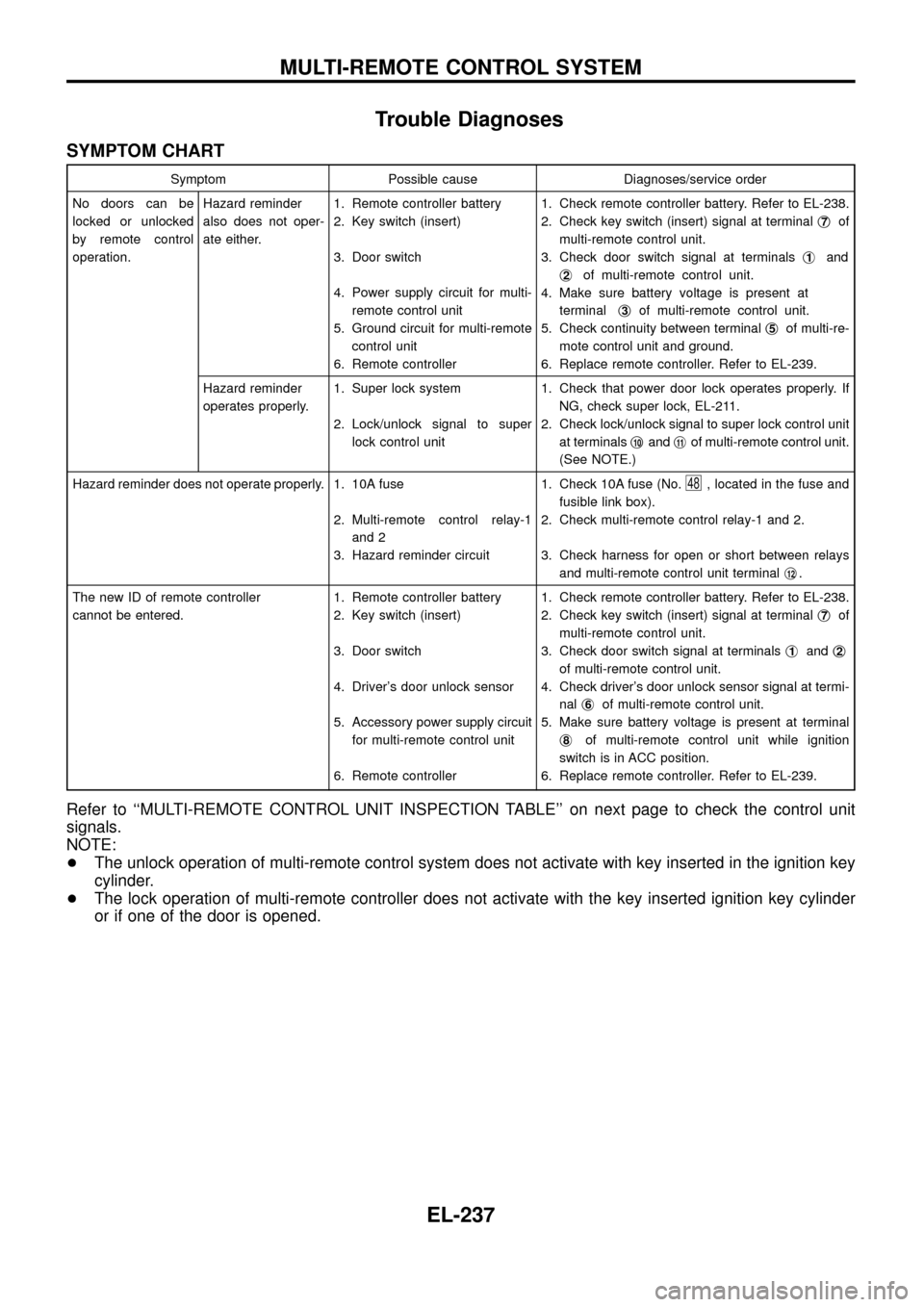
Trouble Diagnoses
SYMPTOM CHART
Symptom Possible cause Diagnoses/service order
No doors can be
locked or unlocked
by remote control
operation.Hazard reminder
also does not oper-
ate either.1. Remote controller battery
2. Key switch (insert)
3. Door switch
4. Power supply circuit for multi-
remote control unit
5. Ground circuit for multi-remote
control unit
6. Remote controller1. Check remote controller battery. Refer to EL-238.
2. Check key switch (insert) signal at terminalj
7of
multi-remote control unit.
3. Check door switch signal at terminalsj
1and
j
2of multi-remote control unit.
4. Make sure battery voltage is present at
terminalj
3of multi-remote control unit.
5. Check continuity between terminalj
5of multi-re-
mote control unit and ground.
6. Replace remote controller. Refer to EL-239.
Hazard reminder
operates properly.1. Super lock system
2. Lock/unlock signal to super
lock control unit1. Check that power door lock operates properly. If
NG, check super lock, EL-211.
2. Check lock/unlock signal to super lock control unit
at terminalsj
10andj11of multi-remote control unit.
(See NOTE.)
Hazard reminder does not operate properly. 1. 10A fuse
2. Multi-remote control relay-1
and 2
3. Hazard reminder circuit1. Check 10A fuse (No.
48, located in the fuse and
fusible link box).
2. Check multi-remote control relay-1 and 2.
3. Check harness for open or short between relays
and multi-remote control unit terminalj
12.
The new ID of remote controller
cannot be entered.1. Remote controller battery
2. Key switch (insert)
3. Door switch
4. Driver's door unlock sensor
5. Accessory power supply circuit
for multi-remote control unit
6. Remote controller1. Check remote controller battery. Refer to EL-238.
2. Check key switch (insert) signal at terminalj
7of
multi-remote control unit.
3. Check door switch signal at terminalsj
1andj2
of multi-remote control unit.
4. Check driver's door unlock sensor signal at termi-
nalj
6of multi-remote control unit.
5. Make sure battery voltage is present at terminal
j
8of multi-remote control unit while ignition
switch is in ACC position.
6. Replace remote controller. Refer to EL-239.
Refer to ``MULTI-REMOTE CONTROL UNIT INSPECTION TABLE'' on next page to check the control unit
signals.
NOTE:
+The unlock operation of multi-remote control system does not activate with key inserted in the ignition key
cylinder.
+The lock operation of multi-remote controller does not activate with the key inserted ignition key cylinder
or if one of the door is opened.
MULTI-REMOTE CONTROL SYSTEM
EL-237