1998 NISSAN PATROL Button
[x] Cancel search: ButtonPage 177 of 326
CATS (Code) System/RHD
NOTE:
+This system is used for code indicator-equipped radios on all models except the Europe LHD
model.
+The Europe LHD model has a NATS-linked anti-theft function that renders the code system inop-
erable.
DESCRIPTION
By using a personal 4-digit code known only to the vehicle owner, the possibility of the audio unit being sto-
len is effectively reduced, because without the code the unit can not be activated. When in normal use, the
unit is unlocked and accessible in the usual way.
If however, someone attempts to remove the unit or the battery cable is disconnected, the anti-theft system
activates and the unit ``locks''. The only way it can be unlocked is by entering a personal code number known
only by the owner.
UNLOCKING THE UNIT (How to enter a personal code number)
+If the battery supply to the vehicle is interrupted by accident for some reason, the unit will lock.
To unlock the unit, proceed as follows:
1. Press the power/volume control knob to turn the unit on.
2. ``CODE IN'' is displayed.
3. Input your personal code by pressing the preset buttons (1 to 4).
4. Press the
button.
5. If the entered code number is correct, the radio turns on.
When the code is incorrect
1. If the entered code is incorrect, the unit becomes inoperable for 10 seconds for the ®rst three attempts,
then the code input mode is automatically set (``CODE IN'' is displayed).
2. If the code is incorrect the fourth time, the unit becomes inoperable for 60 minutes and ``
'' is displayed.
After 60 minutes, the code input mode is automatically set (``CODE IN'' is displayed).
NOTE:
If the above is repeated 17 times, the unit will lock and ``LOCKED'' is displayed.
3. After ``LOCKED'' is displayed, radio can be returned to the code input mode only within three attempts as
follows. (Only three attempts are allowed to unlock the unit.)
a. Press the power/volume control knob while pushing both the MOD and TA switches.
b. The unit then returns to the code input mode.
CAUTION:
If the third attempt is unsuccessful, the unit will lock permanently.
AUDIO
EL-173
Page 184 of 326
Trouble Diagnoses
CD AUTOCHANGER
Symptom Possible causes Repair order
No play of the CD after CD play button
is pushed.
There is no error code shown on
the radio.1. Radio
(The radio is not working.)
2. Harness connection
(Magazine does not eject.)
3. Changer1. Remove the radio for repair.
2. Check harness connection.
3. Remove the changer for repair.
Error code [ERR] is shown on the
radio.1. Discs
2. Magazine does not eject or a
disc remains in CD player.
3. Changer1. Inspect discs.
(Refer to testing magazines and discs.)
2. Reset the changer.
(Disconnect harness connector at the changer and reconnect
after 30 sec.)
3. Remove the changer for repair.
CD skipping. 1. Rough road driving
2. Discs
3. Bracket
4. Changer1. System is not malfunctioning.
2. Inspect discs.
(Refer to testing magazines and discs.)
3. Check and repair bracket and installation of changer.
4. Remove the changer for repair.
Error code [NO DISC] is shown on the
radio after CD play button is pressed.1. Magazine setting
2. Magazine
3. Changer1. Con®rm the magazine is pushed completely.
2. Inspect magazine.
(Refer to testing magazines and discs.)
3. Remove the changer for repair.
Testing magazines and discs
1. Con®rm discs are installed correctly into the magazine (not upside down).
2. Visually inspect/compare the customer's discs with each other and other discs.
Identify any of the following conditions:
+Discs with a large outside diameter. [Normal size is 120 mm (4.72 in).]
+Discs with rough or lipped edges.
+Discs with excessive thickness [Normal size is 1.2 mm (0.047 in).]
+Discs with scratches, abrasions, or pits on the surface.
+Discs with grease/oil, ®ngerprints, foreign material.
+Discs are warped due to excessive heat exposure.
3. Slide/place the discs in and out of the various magazine positions.
Identify any discs and/or positions that require additional force for placement/ejection. If interference
(sticking, excessive tensions) is found, replace the magazine or the discs.
Note:
+Discs which are marginally out of speci®cation (ex. dirty, scratched and so on) may play correctly
on a home stereo.
However, when used in the automotive environment skipping may occur due to the added vehicle
movement and/or vibration due to road conditions. Autochangers should not be replaced when
discs are at fault.
+Use a soft damp cloth to wipe the discs starting from the center outward in radial direction. Never
use chemical cleaning solutions to clean the discs.
AUDIO Ð CD AUTO CHANGER Ð
EL-180
Page 216 of 326
System Description
OUTLINE
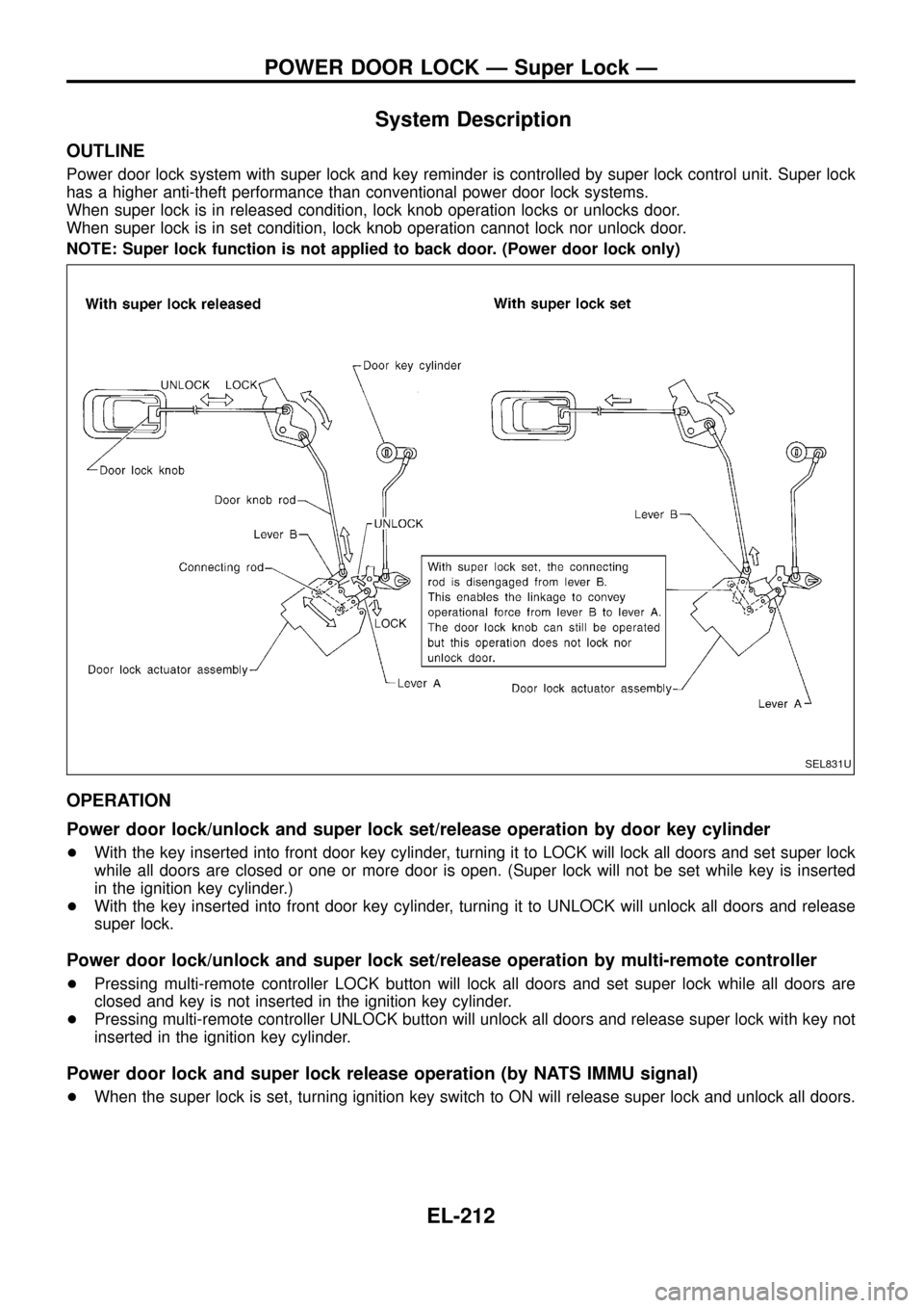
Power door lock system with super lock and key reminder is controlled by super lock control unit. Super lock
has a higher anti-theft performance than conventional power door lock systems.
When super lock is in released condition, lock knob operation locks or unlocks door.
When super lock is in set condition, lock knob operation cannot lock nor unlock door.
NOTE: Super lock function is not applied to back door. (Power door lock only)
OPERATION
Power door lock/unlock and super lock set/release operation by door key cylinder
+With the key inserted into front door key cylinder, turning it to LOCK will lock all doors and set super lock
while all doors are closed or one or more door is open. (Super lock will not be set while key is inserted
in the ignition key cylinder.)
+With the key inserted into front door key cylinder, turning it to UNLOCK will unlock all doors and release
super lock.
Power door lock/unlock and super lock set/release operation by multi-remote controller
+Pressing multi-remote controller LOCK button will lock all doors and set super lock while all doors are
closed and key is not inserted in the ignition key cylinder.
+Pressing multi-remote controller UNLOCK button will unlock all doors and release super lock with key not
inserted in the ignition key cylinder.
Power door lock and super lock release operation (by NATS IMMU signal)
+When the super lock is set, turning ignition key switch to ON will release super lock and unlock all doors.
SEL831U
POWER DOOR LOCK Ð Super Lock Ð
EL-212
Page 237 of 326
DIAGNOSTIC PROCEDURE 9
(Remote controller signal check)
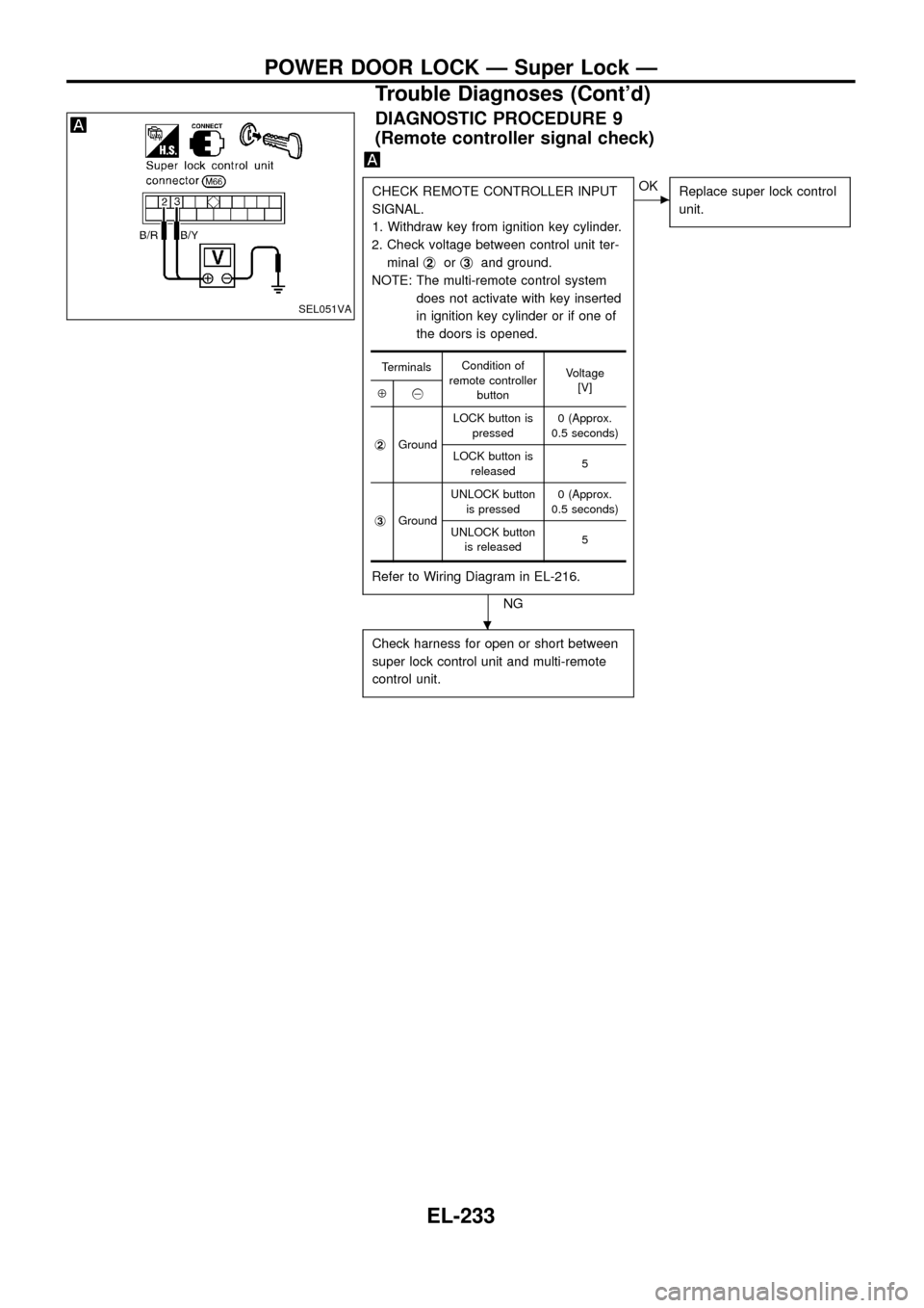
CHECK REMOTE CONTROLLER INPUT
SIGNAL.
1. Withdraw key from ignition key cylinder.
2. Check voltage between control unit ter-
minalj
2orj3and ground.
NOTE: The multi-remote control system
does not activate with key inserted
in ignition key cylinder or if one of
the doors is opened.
Refer to Wiring Diagram in EL-216.
NG
cOK
Replace super lock control
unit.
Check harness for open or short between
super lock control unit and multi-remote
control unit.
TerminalsCondition of
remote controller
buttonVoltage
[V]
Å@
j
2GroundLOCK button is
pressed0 (Approx.
0.5 seconds)
LOCK button is
released5
j
3GroundUNLOCK button
is pressed0 (Approx.
0.5 seconds)
UNLOCK button
is released5
SEL051VA
.
POWER DOOR LOCK Ð Super Lock Ð
Trouble Diagnoses (Cont'd)
EL-233
Page 242 of 326
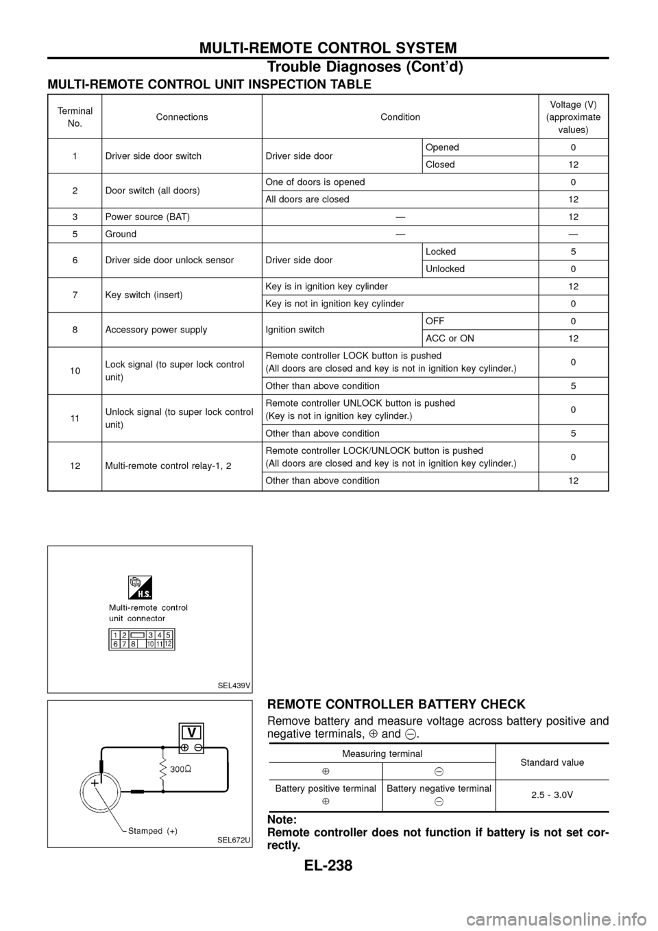
MULTI-REMOTE CONTROL UNIT INSPECTION TABLE
Terminal
No.Connections ConditionVoltage (V)
(approximate
values)
1 Driver side door switch Driver side doorOpened 0
Closed 12
2 Door switch (all doors)One of doors is opened 0
All doors are closed 12
3 Power source (BAT) Ð 12
5 Ground Ð Ð
6 Driver side door unlock sensor Driver side doorLocked 5
Unlocked 0
7 Key switch (insert)Key is in ignition key cylinder 12
Key is not in ignition key cylinder 0
8 Accessory power supply Ignition switchOFF 0
ACC or ON 12
10Lock signal (to super lock control
unit)Remote controller LOCK button is pushed
(All doors are closed and key is not in ignition key cylinder.)0
Other than above condition 5
11Unlock signal (to super lock control
unit)Remote controller UNLOCK button is pushed
(Key is not in ignition key cylinder.)0
Other than above condition 5
12 Multi-remote control relay-1, 2Remote controller LOCK/UNLOCK button is pushed
(All doors are closed and key is not in ignition key cylinder.)0
Other than above condition 12
REMOTE CONTROLLER BATTERY CHECK
Remove battery and measure voltage across battery positive and
negative terminals,Åand@.
Measuring terminal
Standard value
Å@
Battery positive terminal
ÅBattery negative terminal
@2.5 - 3.0V
Note:
Remote controller does not function if battery is not set cor-
rectly.
SEL439V
SEL672U
MULTI-REMOTE CONTROL SYSTEM
Trouble Diagnoses (Cont'd)
EL-238
Page 243 of 326
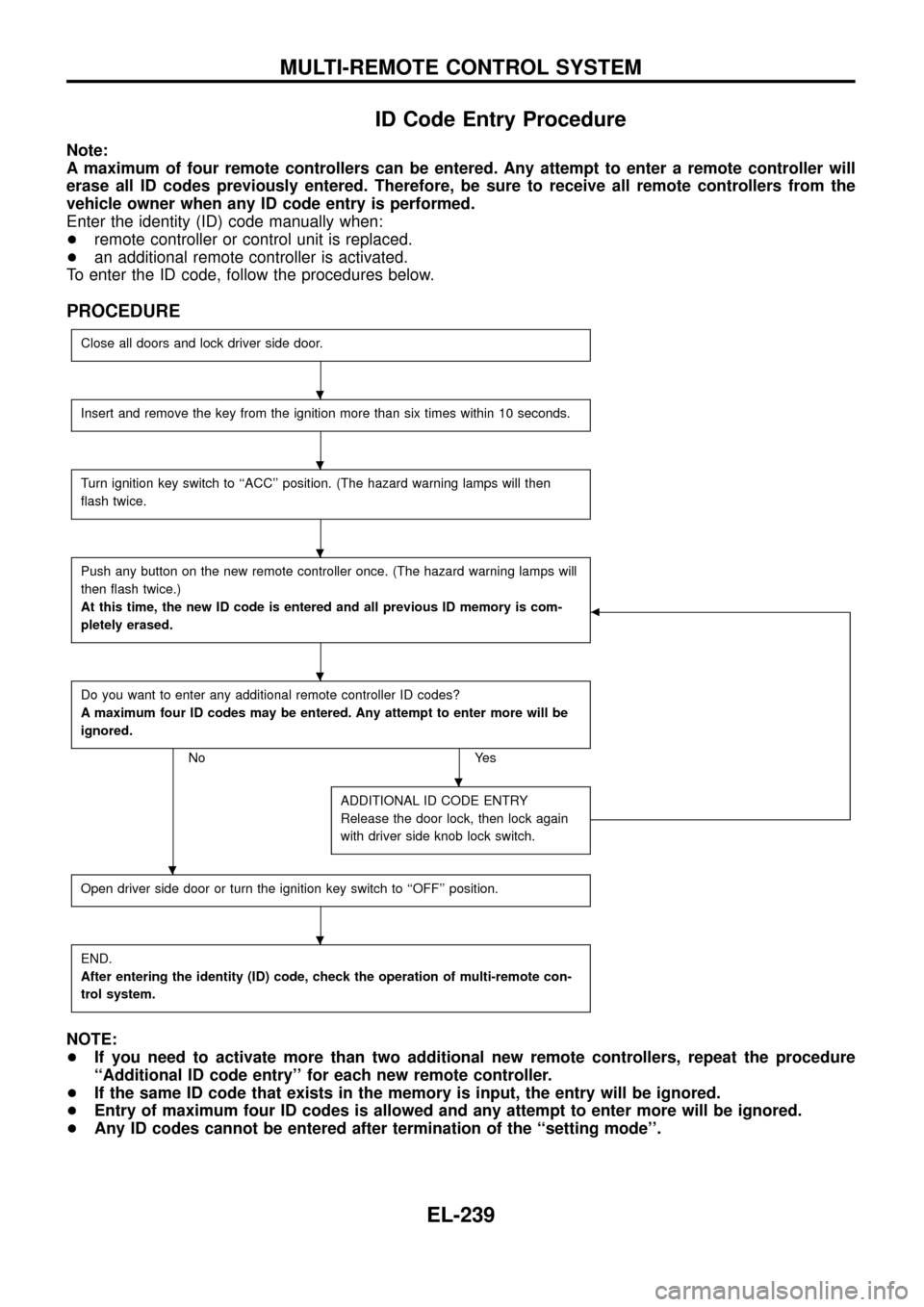
ID Code Entry Procedure
Note:
A maximum of four remote controllers can be entered. Any attempt to enter a remote controller will
erase all ID codes previously entered. Therefore, be sure to receive all remote controllers from the
vehicle owner when any ID code entry is performed.
Enter the identity (ID) code manually when:
+remote controller or control unit is replaced.
+an additional remote controller is activated.
To enter the ID code, follow the procedures below.
PROCEDURE
Close all doors and lock driver side door.
Insert and remove the key from the ignition more than six times within 10 seconds.
Turn ignition key switch to ``ACC'' position. (The hazard warning lamps will then
¯ash twice.
Push any button on the new remote controller once. (The hazard warning lamps will
then ¯ash twice.)
At this time, the new ID code is entered and all previous ID memory is com-
pletely erased.
b
Do you want to enter any additional remote controller ID codes?
A maximum four ID codes may be entered. Any attempt to enter more will be
ignored.
No Yes
ADDITIONAL ID CODE ENTRY
Release the door lock, then lock again
with driver side knob lock switch.
Open driver side door or turn the ignition key switch to ``OFF'' position.
END.
After entering the identity (ID) code, check the operation of multi-remote con-
trol system.
NOTE:
+If you need to activate more than two additional new remote controllers, repeat the procedure
``Additional ID code entry'' for each new remote controller.
+If the same ID code that exists in the memory is input, the entry will be ignored.
+Entry of maximum four ID codes is allowed and any attempt to enter more will be ignored.
+Any ID codes cannot be entered after termination of the ``setting mode''.
.
.
.
.
.
.
.
MULTI-REMOTE CONTROL SYSTEM
EL-239