1998 NISSAN PATROL fuse
[x] Cancel search: fusePage 122 of 326
Trouble Diagnoses
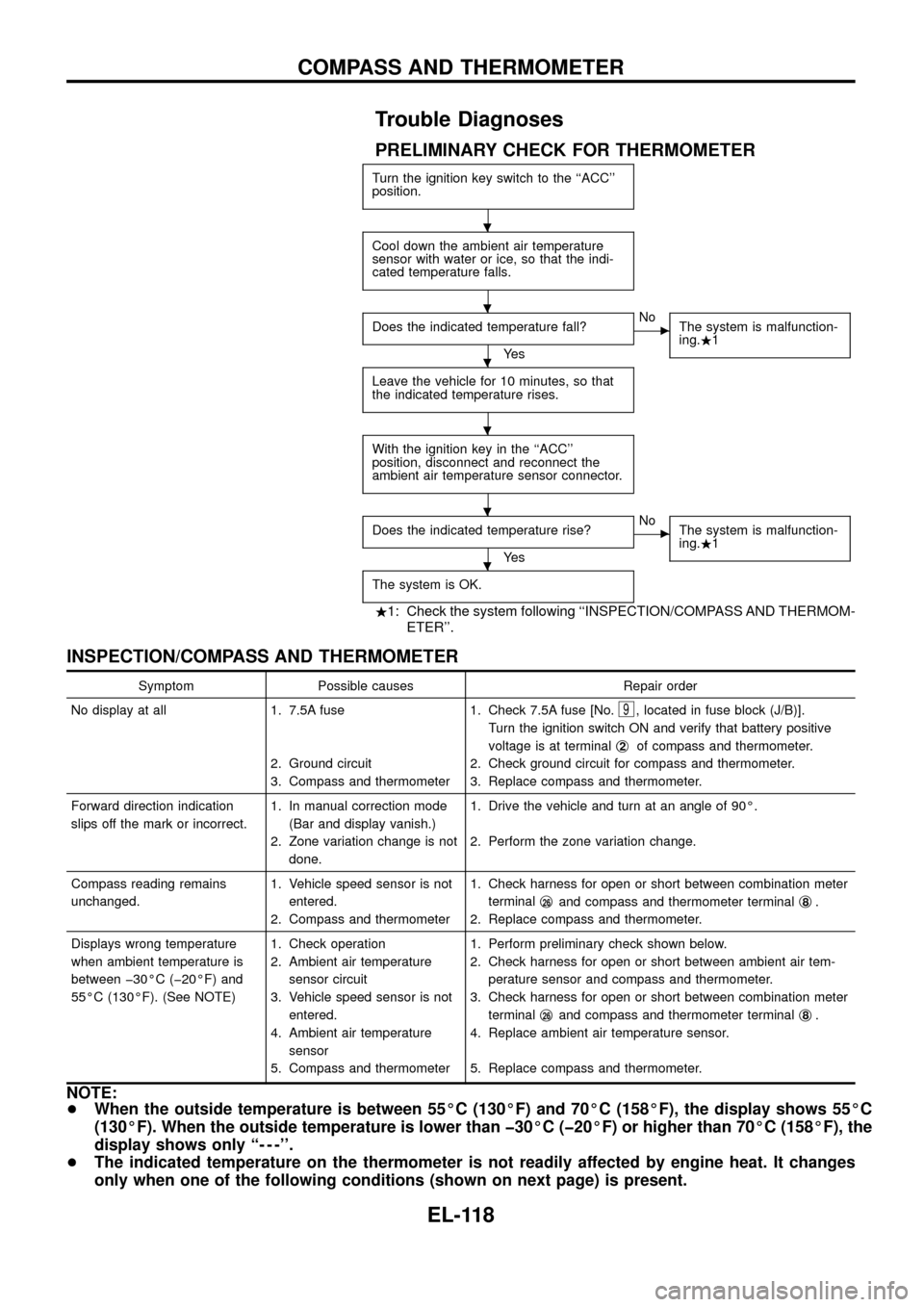
PRELIMINARY CHECK FOR THERMOMETER
Turn the ignition key switch to the ``ACC''
position.
Cool down the ambient air temperature
sensor with water or ice, so that the indi-
cated temperature falls.
Does the indicated temperature fall?
Ye s
cNo
The system is malfunction-
ing..1
Leave the vehicle for 10 minutes, so that
the indicated temperature rises.
With the ignition key in the ``ACC''
position, disconnect and reconnect the
ambient air temperature sensor connector.
Does the indicated temperature rise?
Ye s
cNo
The system is malfunction-
ing..1
The system is OK.
.1: Check the system following ``INSPECTION/COMPASS AND THERMOM-
ETER''.
INSPECTION/COMPASS AND THERMOMETER
Symptom Possible causes Repair order
No display at all 1. 7.5A fuse
2. Ground circuit
3. Compass and thermometer1. Check 7.5A fuse [No.
9, located in fuse block (J/B)].
Turn the ignition switch ON and verify that battery positive
voltage is at terminalj
2of compass and thermometer.
2. Check ground circuit for compass and thermometer.
3. Replace compass and thermometer.
Forward direction indication
slips off the mark or incorrect.1. In manual correction mode
(Bar and display vanish.)
2. Zone variation change is not
done.1. Drive the vehicle and turn at an angle of 90É.
2. Perform the zone variation change.
Compass reading remains
unchanged.1. Vehicle speed sensor is not
entered.
2. Compass and thermometer1. Check harness for open or short between combination meter
terminalj
26and compass and thermometer terminalj8.
2. Replace compass and thermometer.
Displays wrong temperature
when ambient temperature is
between þ30ÉC (þ20ÉF) and
55ÉC (130ÉF). (See NOTE)1. Check operation
2. Ambient air temperature
sensor circuit
3. Vehicle speed sensor is not
entered.
4. Ambient air temperature
sensor
5. Compass and thermometer1. Perform preliminary check shown below.
2. Check harness for open or short between ambient air tem-
perature sensor and compass and thermometer.
3. Check harness for open or short between combination meter
terminalj
26and compass and thermometer terminalj8.
4. Replace ambient air temperature sensor.
5. Replace compass and thermometer.
NOTE:
+When the outside temperature is between 55ÉC (130ÉF) and 70ÉC (158ÉF), the display shows 55ÉC
(130ÉF). When the outside temperature is lower than þ30ÉC (þ20ÉF) or higher than 70ÉC (158ÉF), the
display shows only ``- - -''.
+The indicated temperature on the thermometer is not readily affected by engine heat. It changes
only when one of the following conditions (shown on next page) is present.
.
.
.
.
.
.
COMPASS AND THERMOMETER
EL-118
Page 142 of 326
Trouble Diagnoses
SYMPTOM CHART
REFERENCE PAGE EL-138 EL-139 EL-139
SYMPTOM
DIAGNOSTIC PROCEDURE 1
(Lighting switch input signal check)
DIAGNOSTIC PROCEDURE 2
(Key switch input signal check)
DIAGNOSTIC PROCEDURE 3
Light warning chime does not acti-
vate.XX
Ignition key warning chime does not
activate.XX
All warning chimes do not activate.X
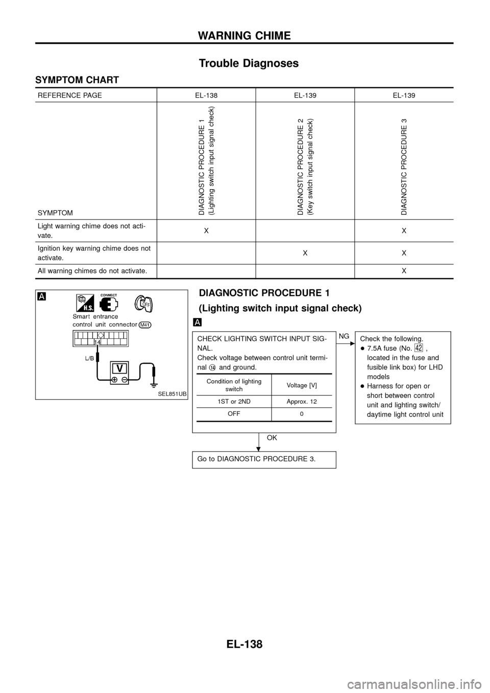
DIAGNOSTIC PROCEDURE 1
(Lighting switch input signal check)
CHECK LIGHTING SWITCH INPUT SIG-
NAL.
Check voltage between control unit termi-
nalj
14and ground.
OK
cNG
Check the following.
+7.5A fuse (No.
42,
located in the fuse and
fusible link box) for LHD
models
+Harness for open or
short between control
unit and lighting switch/
daytime light control unit
Go to DIAGNOSTIC PROCEDURE 3.
Condition of lighting
switchVoltage [V]
1ST or 2ND Approx. 12
OFF 0
SEL851UB
.
WARNING CHIME
EL-138
Page 143 of 326
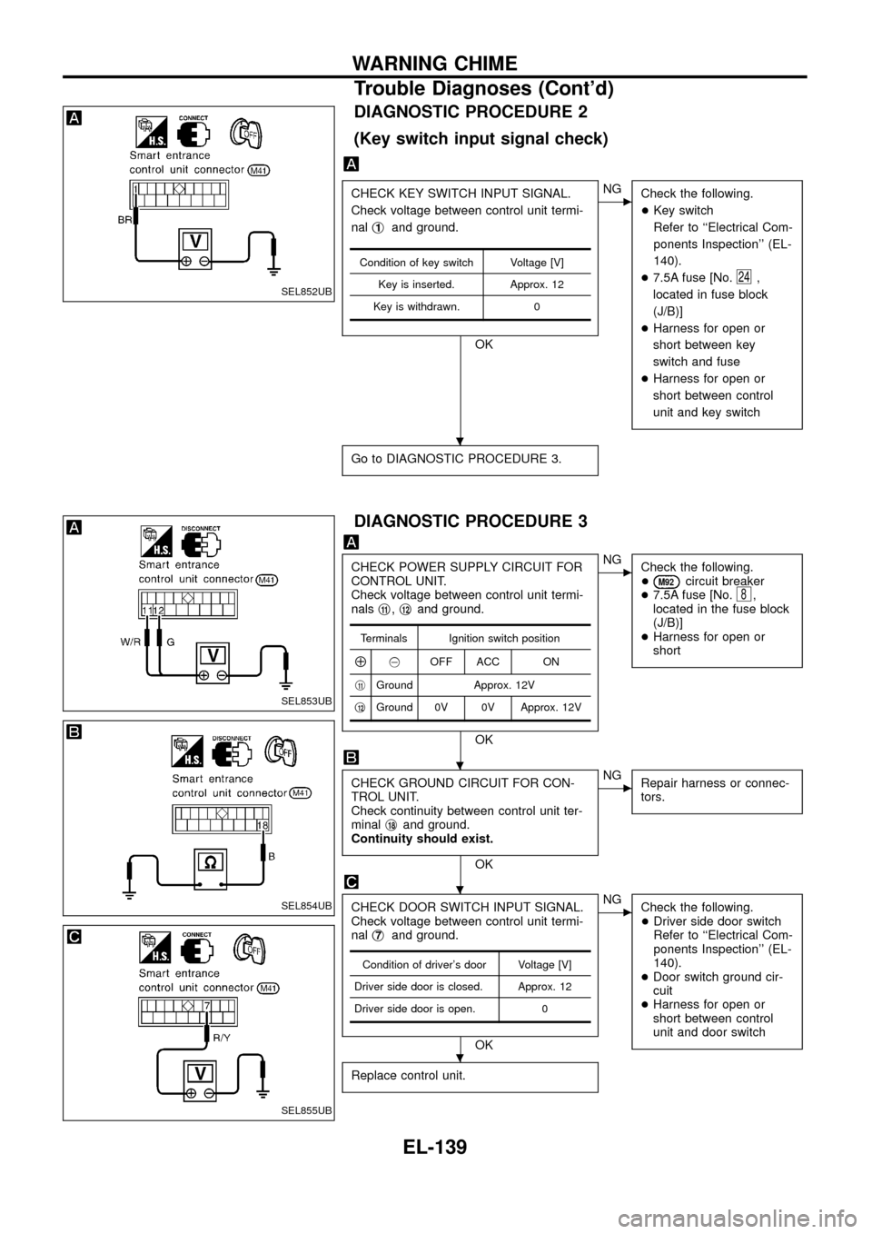
DIAGNOSTIC PROCEDURE 2
(Key switch input signal check)
CHECK KEY SWITCH INPUT SIGNAL.
Check voltage between control unit termi-
nalj
1and ground.
OK
cNG
Check the following.
+Key switch
Refer to ``Electrical Com-
ponents Inspection'' (EL-
140).
+7.5A fuse [No.
24,
located in fuse block
(J/B)]
+Harness for open or
short between key
switch and fuse
+Harness for open or
short between control
unit and key switch
Go to DIAGNOSTIC PROCEDURE 3.
Condition of key switch Voltage [V]
Key is inserted. Approx. 12
Key is withdrawn. 0
DIAGNOSTIC PROCEDURE 3
CHECK POWER SUPPLY CIRCUIT FOR
CONTROL UNIT.
Check voltage between control unit termi-
nalsj
11,j12and ground.
OK
cNG
Check the following.
+
M92circuit breaker
+7.5A fuse [No.8,
located in the fuse block
(J/B)]
+Harness for open or
short
CHECK GROUND CIRCUIT FOR CON-
TROL UNIT.
Check continuity between control unit ter-
minalj
18and ground.
Continuity should exist.
OK
cNG
Repair harness or connec-
tors.
CHECK DOOR SWITCH INPUT SIGNAL.
Check voltage between control unit termi-
nalj
7and ground.
OK
cNG
Check the following.
+Driver side door switch
Refer to ``Electrical Com-
ponents Inspection'' (EL-
140).
+Door switch ground cir-
cuit
+Harness for open or
short between control
unit and door switch
Replace control unit.
Terminals Ignition switch position
Å@OFF ACC ON
j
11Ground Approx. 12V
j
12Ground 0V 0V Approx. 12V
Condition of driver's door Voltage [V]
Driver side door is closed. Approx. 12
Driver side door is open. 0
SEL852UB
SEL853UB
SEL854UB
SEL855UB
.
.
.
.
WARNING CHIME
Trouble Diagnoses (Cont'd)
EL-139
Page 145 of 326
System Description
WIPER OPERATION
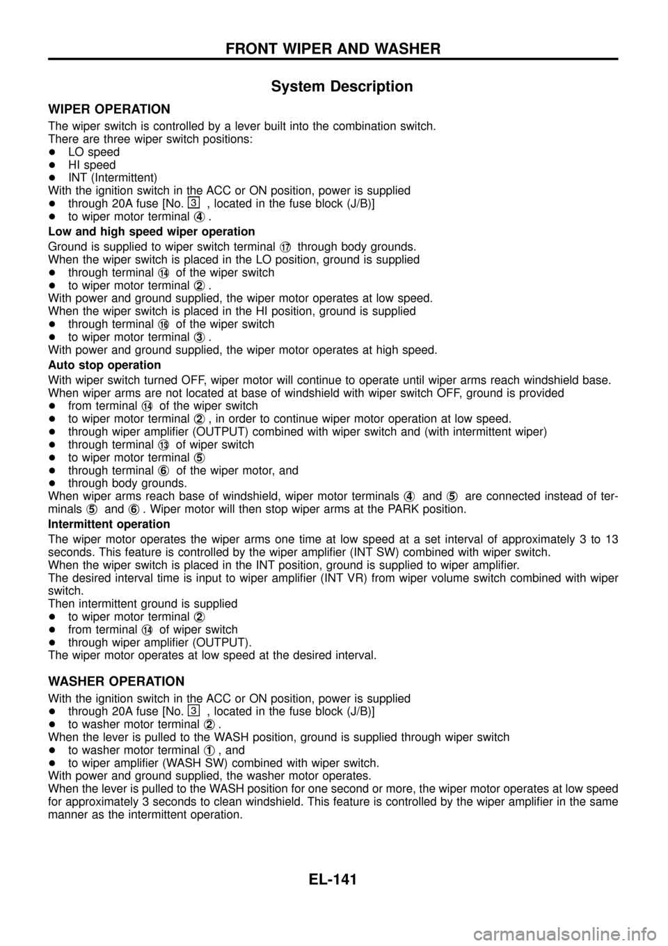
The wiper switch is controlled by a lever built into the combination switch.
There are three wiper switch positions:
+LO speed
+HI speed
+INT (Intermittent)
With the ignition switch in the ACC or ON position, power is supplied
+through 20A fuse [No.
, located in the fuse block (J/B)]
+to wiper motor terminalj
4.
Low and high speed wiper operation
Ground is supplied to wiper switch terminalj
17through body grounds.
When the wiper switch is placed in the LO position, ground is supplied
+through terminalj
14of the wiper switch
+to wiper motor terminalj
2.
With power and ground supplied, the wiper motor operates at low speed.
When the wiper switch is placed in the HI position, ground is supplied
+through terminalj
16of the wiper switch
+to wiper motor terminalj
3.
With power and ground supplied, the wiper motor operates at high speed.
Auto stop operation
With wiper switch turned OFF, wiper motor will continue to operate until wiper arms reach windshield base.
When wiper arms are not located at base of windshield with wiper switch OFF, ground is provided
+from terminalj
14of the wiper switch
+to wiper motor terminalj
2, in order to continue wiper motor operation at low speed.
+through wiper ampli®er (OUTPUT) combined with wiper switch and (with intermittent wiper)
+through terminalj
13of wiper switch
+to wiper motor terminalj
5
+through terminalj6of the wiper motor, and
+through body grounds.
When wiper arms reach base of windshield, wiper motor terminalsj
4andj5are connected instead of ter-
minalsj
5andj6. Wiper motor will then stop wiper arms at the PARK position.
Intermittent operation
The wiper motor operates the wiper arms one time at low speed at a set interval of approximately 3 to 13
seconds. This feature is controlled by the wiper ampli®er (INT SW) combined with wiper switch.
When the wiper switch is placed in the INT position, ground is supplied to wiper ampli®er.
The desired interval time is input to wiper ampli®er (INT VR) from wiper volume switch combined with wiper
switch.
Then intermittent ground is supplied
+to wiper motor terminalj
2
+from terminalj14of wiper switch
+through wiper ampli®er (OUTPUT).
The wiper motor operates at low speed at the desired interval.
WASHER OPERATION
With the ignition switch in the ACC or ON position, power is supplied
+through 20A fuse [No.
, located in the fuse block (J/B)]
+to washer motor terminalj
2.
When the lever is pulled to the WASH position, ground is supplied through wiper switch
+to washer motor terminalj
1, and
+to wiper ampli®er (WASH SW) combined with wiper switch.
With power and ground supplied, the washer motor operates.
When the lever is pulled to the WASH position for one second or more, the wiper motor operates at low speed
for approximately 3 seconds to clean windshield. This feature is controlled by the wiper ampli®er in the same
manner as the intermittent operation.
FRONT WIPER AND WASHER
EL-141
Page 149 of 326
System Description
WIPER OPERATION
The rear wiper switch is controlled by a ring built into the combination switch.
There are two wiper switch positions:
+ON (LO speed)
+INT (Intermittent)
With the ignition switch in the ON position, power is supplied
+through 10A fuse (No.
18, located in the fuse block)
+to rear wiper motor terminalj
4, and
+to rear wiper ampli®er terminalj
5.
Low speed wiper operation
Ground is supplied to rear wiper switch terminalj24through body grounds.
When the rear wiper is placed in the ON position, ground is supplied
+through rear wiper switch terminalj
22
+to rear wiper relay terminalj6.
Then ground is supplied
+to rear wiper motor terminalj
1
+through rear wiper ampli®er terminalsj2andj3.
With power and ground supplied, the wiper motor operates.
Auto stop operation
With the rear wiper switch turned OFF, rear wiper motor will continue to operate until wiper arm reaches rear
window base.
When wiper arm is not located at base of rear window with rear wiper switch OFF, ground is supplied
+to rear wiper motor terminalj
1
+through rear wiper ampli®er terminalsj2,j7and
+through rear wiper motor terminalj
3, in order to continue rear wiper motor operation at low speed.
Ground is also supplied
+to rear wiper motor terminalj
2
+through body grounds.
When wiper arm reaches base of rear window, rear wiper motor terminalsj
3andj4are connected instead
of terminalsj
2andj3. Rear wiper motor will then stop wiper arm at the PARK position.
Intermittent operation
The rear wiper motor operates the wiper arm one time at low speed at an interval of approximately 7 sec-
onds.
When the rear wiper switch is placed in the INT position, ground is supplied
+to rear wiper ampli®er terminalj
1
+through rear wiper switch terminalj21.
Then the rear wiper motor operates intermittently in the same manner as the low speed wiper operation.
WASHER OPERATION
With the ignition switch in the ACC or ON position, power is supplied
+through 10A fuse (No.
18, located in the fuse block)
+to rear washer motor terminalj
2.
When the ring is turned WASH position, ground is supplied
+to rear washer motor terminalj
1, and
+to rear wiper ampli®er terminalj
4
+through terminalj23of rear wiper switch.
With power and ground is supplied, the rear washer motor operates.
The rear wiper motor operates when the ring is turned to WASH position for one second or more and for
approximately 3 seconds after the ring is released. This feature is controlled by the rear wiper ampli®er in the
same manner as the low speed wiper operation.
REAR WIPER AND WASHER
EL-145
Page 162 of 326
System Description
The rear window defogger system is controlled by the smart entrance control unit. The rear window defogger
operates only for approximately 15 minutes.
Power is supplied at all times
+to rear window defogger relay terminalj
3
+through 15A fuse (No.43, located in the fuse and fusible link box) and
+to rear window defogger relay terminalj
6
+through 20A fuse (No.44, located in the fuse and fusible link box).
With the ignition switch in the ON or START position, power is supplied
+to the rear window defogger relay terminalj
1and
+to smart entrance control unit terminalj
12
+through 7.5A fuse [No.8, located in the fuse block (J/B)].
Ground is supplied to terminalj
2of the rear window defogger switch through body grounds.
When the rear window defogger switch is turned ON, ground is supplied
+through terminalj
1of the rear window defogger switch
+to smart entrance control unit terminalj
8.
Terminalj
9of the smart entrance control unit then supplies ground to the rear window defogger relay termi-
nalj
2.
With power and ground supplied, the rear window defogger relay is energized.
Power is supplied
+through terminalsj
5andj7of the rear window defogger relay
+to the rear window defogger.
The rear window defogger has an independent ground.
With power and ground supplied, the rear window defogger ®laments heat and defog the rear window.
When the system is activated, the rear window defogger indicator illuminates in the rear window defogger
switch.
Power is supplied
+to terminalj
3of the rear window defogger switch
+from terminalj
5of the rear window defogger relay.
Terminalj
4of the rear window defogger switch is grounded through body grounds.
REAR WINDOW DEFOGGER
EL-158
Page 167 of 326
Trouble Diagnoses
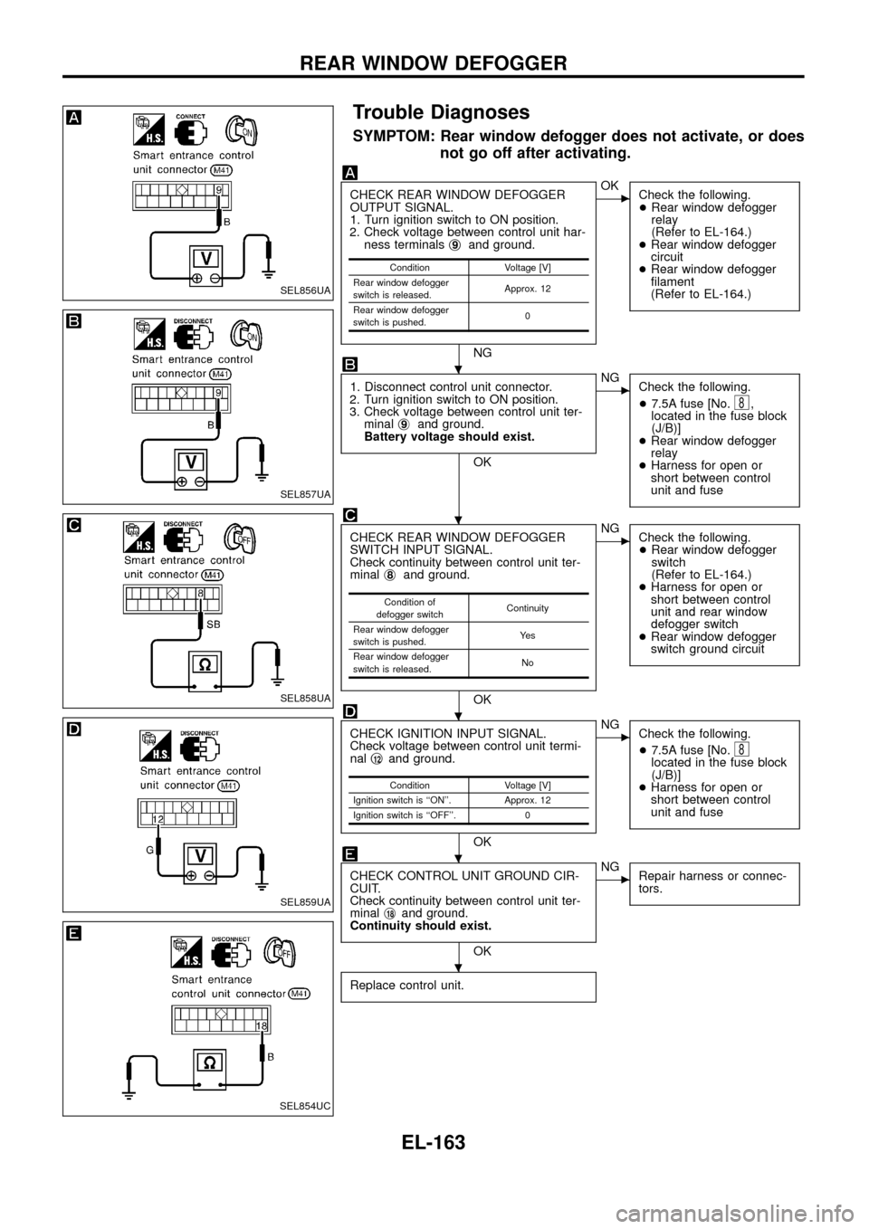
SYMPTOM: Rear window defogger does not activate, or does
not go off after activating.
CHECK REAR WINDOW DEFOGGER
OUTPUT SIGNAL.
1. Turn ignition switch to ON position.
2. Check voltage between control unit har-
ness terminalsj
9and ground.
NG
cOK
Check the following.
+Rear window defogger
relay
(Refer to EL-164.)
+Rear window defogger
circuit
+Rear window defogger
®lament
(Refer to EL-164.)
1. Disconnect control unit connector.
2. Turn ignition switch to ON position.
3. Check voltage between control unit ter-
minalj
9and ground.
Battery voltage should exist.
OK
cNG
Check the following.
+7.5A fuse [No.
8,
located in the fuse block
(J/B)]
+Rear window defogger
relay
+Harness for open or
short between control
unit and fuse
CHECK REAR WINDOW DEFOGGER
SWITCH INPUT SIGNAL.
Check continuity between control unit ter-
minalj
8and ground.
OK
cNG
Check the following.
+Rear window defogger
switch
(Refer to EL-164.)
+Harness for open or
short between control
unit and rear window
defogger switch
+Rear window defogger
switch ground circuit
CHECK IGNITION INPUT SIGNAL.
Check voltage between control unit termi-
nalj
12and ground.
OK
cNG
Check the following.
+7.5A fuse [No.
8located in the fuse block
(J/B)]
+Harness for open or
short between control
unit and fuse
CHECK CONTROL UNIT GROUND CIR-
CUIT.
Check continuity between control unit ter-
minalj
18and ground.
Continuity should exist.
OK
cNG
Repair harness or connec-
tors.
Replace control unit.
Condition Voltage [V]
Rear window defogger
switch is released.Approx. 12
Rear window defogger
switch is pushed.0
Condition of
defogger switchContinuity
Rear window defogger
switch is pushed.Ye s
Rear window defogger
switch is released.No
Condition Voltage [V]
Ignition switch is ``ON''. Approx. 12
Ignition switch is ``OFF''. 0
SEL856UA
SEL857UA
SEL858UA
SEL859UA
SEL854UC
.
.
.
.
.
REAR WINDOW DEFOGGER
EL-163
Page 176 of 326
Trouble Diagnoses
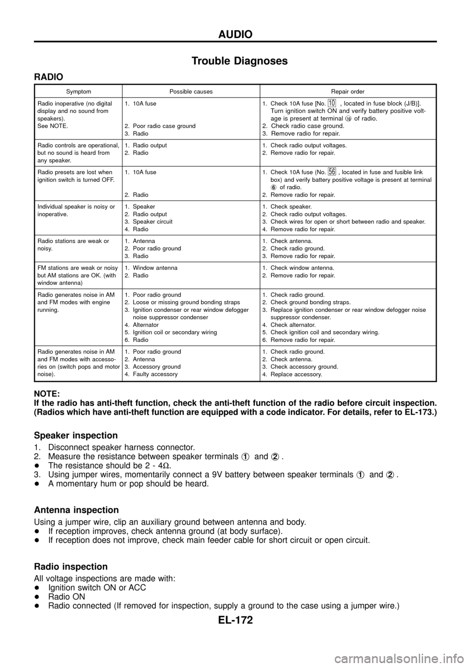
RADIO
Symptom Possible causes Repair order
Radio inoperative (no digital
display and no sound from
speakers).
See NOTE.1. 10A fuse
2. Poor radio case ground
3. Radio1. Check 10A fuse [No.
10, located in fuse block (J/B)].
Turn ignition switch ON and verify battery positive volt-
age is present at terminalj
10of radio.
2. Check radio case ground.
3. Remove radio for repair.
Radio controls are operational,
but no sound is heard from
any speaker.1. Radio output
2. Radio1. Check radio output voltages.
2. Remove radio for repair.
Radio presets are lost when
ignition switch is turned OFF.1. 10A fuse
2. Radio1. Check 10A fuse (No.
56, located in fuse and fusible link
box) and verify battery positive voltage is present at terminal
j
6of radio.
2. Remove radio for repair.
Individual speaker is noisy or
inoperative.1. Speaker
2. Radio output
3. Speaker circuit
4. Radio1. Check speaker.
2. Check radio output voltages.
3. Check wires for open or short between radio and speaker.
4. Remove radio for repair.
Radio stations are weak or
noisy.1. Antenna
2. Poor radio ground
3. Radio1. Check antenna.
2. Check radio ground.
3. Remove radio for repair.
FM stations are weak or noisy
but AM stations are OK. (with
window antenna)1. Window antenna
2. Radio1. Check window antenna.
2. Remove radio for repair.
Radio generates noise in AM
and FM modes with engine
running.1. Poor radio ground
2. Loose or missing ground bonding straps
3. Ignition condenser or rear window defogger
noise suppressor condenser
4. Alternator
5. Ignition coil or secondary wiring
6. Radio1. Check radio ground.
2. Check ground bonding straps.
3. Replace ignition condenser or rear window defogger noise
suppressor condenser.
4. Check alternator.
5. Check ignition coil and secondary wiring.
6. Remove radio for repair.
Radio generates noise in AM
and FM modes with accesso-
ries on (switch pops and motor
noise).1. Poor radio ground
2. Antenna
3. Accessory ground
4. Faulty accessory1. Check radio ground.
2. Check antenna.
3. Check accessory ground.
4. Replace accessory.
NOTE:
If the radio has anti-theft function, check the anti-theft function of the radio before circuit inspection.
(Radios which have anti-theft function are equipped with a code indicator. For details, refer to EL-173.)
Speaker inspection
1. Disconnect speaker harness connector.
2. Measure the resistance between speaker terminalsj
1andj2.
+The resistance should be2-4W.
3. Using jumper wires, momentarily connect a 9V battery between speaker terminalsj
1andj2.
+A momentary hum or pop should be heard.
Antenna inspection
Using a jumper wire, clip an auxiliary ground between antenna and body.
+If reception improves, check antenna ground (at body surface).
+If reception does not improve, check main feeder cable for short circuit or open circuit.
Radio inspection
All voltage inspections are made with:
+Ignition switch ON or ACC
+Radio ON
+Radio connected (If removed for inspection, supply a ground to the case using a jumper wire.)
AUDIO
EL-172