1998 NISSAN PATROL Ignition system
[x] Cancel search: Ignition systemPage 120 of 326
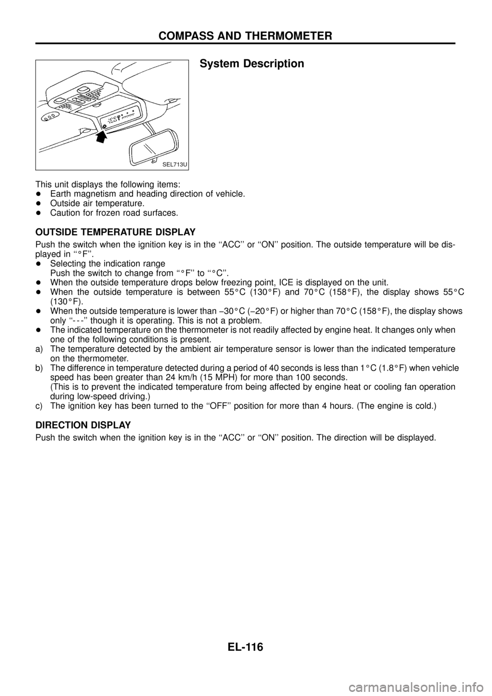
System Description
This unit displays the following items:
+Earth magnetism and heading direction of vehicle.
+Outside air temperature.
+Caution for frozen road surfaces.
OUTSIDE TEMPERATURE DISPLAY
Push the switch when the ignition key is in the ``ACC'' or ``ON'' position. The outside temperature will be dis-
played in ``ÉF''.
+Selecting the indication range
Push the switch to change from ``ÉF'' to ``ÉC''.
+When the outside temperature drops below freezing point, ICE is displayed on the unit.
+When the outside temperature is between 55ÉC (130ÉF) and 70ÉC (158ÉF), the display shows 55ÉC
(130ÉF).
+When the outside temperature is lower than þ30ÉC (þ20ÉF) or higher than 70ÉC (158ÉF), the display shows
only ``- - -'' though it is operating. This is not a problem.
+The indicated temperature on the thermometer is not readily affected by engine heat. It changes only when
one of the following conditions is present.
a) The temperature detected by the ambient air temperature sensor is lower than the indicated temperature
on the thermometer.
b) The difference in temperature detected during a period of 40 seconds is less than 1ÉC (1.8ÉF) when vehicle
speed has been greater than 24 km/h (15 MPH) for more than 100 seconds.
(This is to prevent the indicated temperature from being affected by engine heat or cooling fan operation
during low-speed driving.)
c) The ignition key has been turned to the ``OFF'' position for more than 4 hours. (The engine is cold.)
DIRECTION DISPLAY
Push the switch when the ignition key is in the ``ACC'' or ``ON'' position. The direction will be displayed.
SEL713U
COMPASS AND THERMOMETER
EL-116
Page 122 of 326
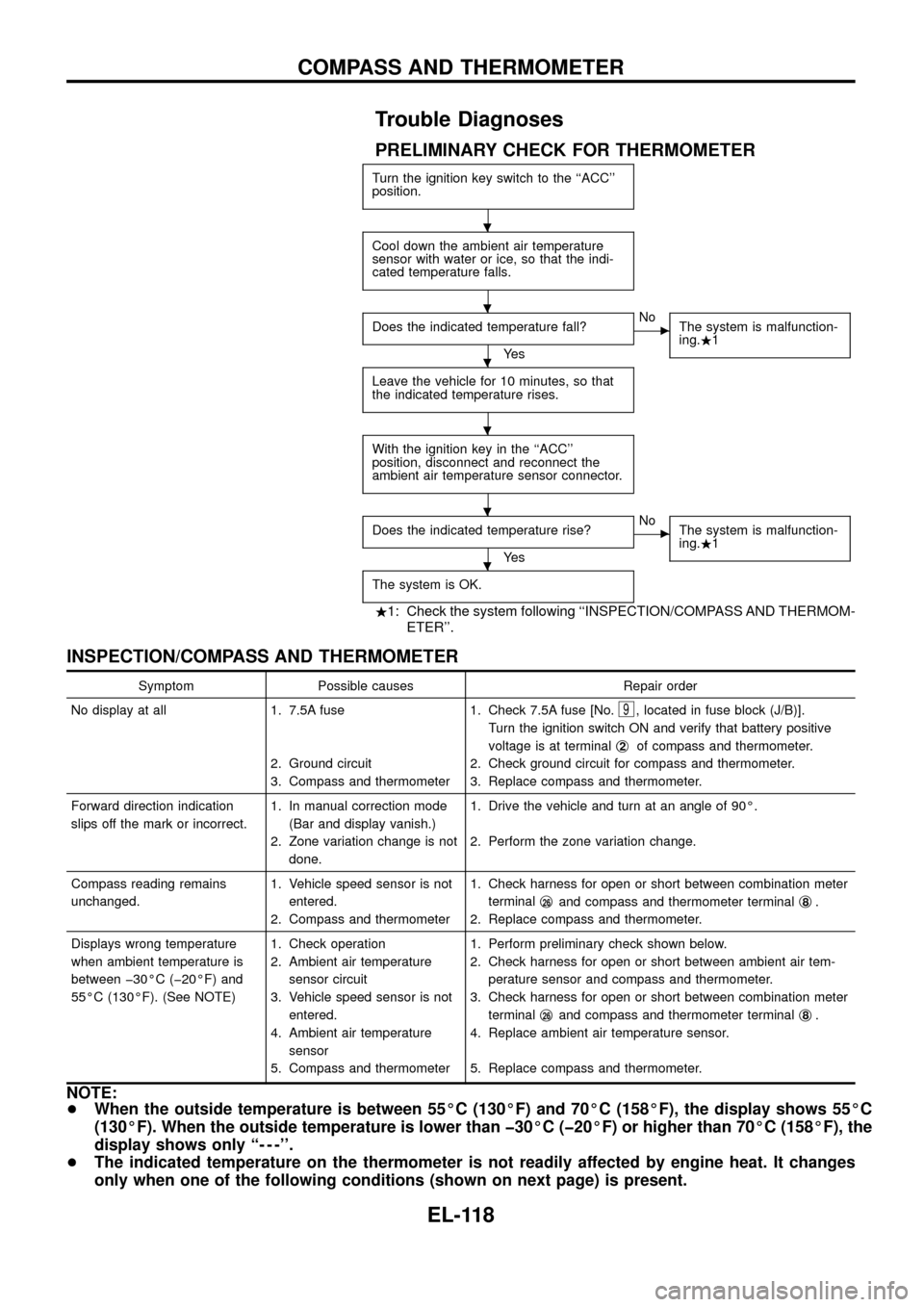
Trouble Diagnoses
PRELIMINARY CHECK FOR THERMOMETER
Turn the ignition key switch to the ``ACC''
position.
Cool down the ambient air temperature
sensor with water or ice, so that the indi-
cated temperature falls.
Does the indicated temperature fall?
Ye s
cNo
The system is malfunction-
ing..1
Leave the vehicle for 10 minutes, so that
the indicated temperature rises.
With the ignition key in the ``ACC''
position, disconnect and reconnect the
ambient air temperature sensor connector.
Does the indicated temperature rise?
Ye s
cNo
The system is malfunction-
ing..1
The system is OK.
.1: Check the system following ``INSPECTION/COMPASS AND THERMOM-
ETER''.
INSPECTION/COMPASS AND THERMOMETER
Symptom Possible causes Repair order
No display at all 1. 7.5A fuse
2. Ground circuit
3. Compass and thermometer1. Check 7.5A fuse [No.
9, located in fuse block (J/B)].
Turn the ignition switch ON and verify that battery positive
voltage is at terminalj
2of compass and thermometer.
2. Check ground circuit for compass and thermometer.
3. Replace compass and thermometer.
Forward direction indication
slips off the mark or incorrect.1. In manual correction mode
(Bar and display vanish.)
2. Zone variation change is not
done.1. Drive the vehicle and turn at an angle of 90É.
2. Perform the zone variation change.
Compass reading remains
unchanged.1. Vehicle speed sensor is not
entered.
2. Compass and thermometer1. Check harness for open or short between combination meter
terminalj
26and compass and thermometer terminalj8.
2. Replace compass and thermometer.
Displays wrong temperature
when ambient temperature is
between þ30ÉC (þ20ÉF) and
55ÉC (130ÉF). (See NOTE)1. Check operation
2. Ambient air temperature
sensor circuit
3. Vehicle speed sensor is not
entered.
4. Ambient air temperature
sensor
5. Compass and thermometer1. Perform preliminary check shown below.
2. Check harness for open or short between ambient air tem-
perature sensor and compass and thermometer.
3. Check harness for open or short between combination meter
terminalj
26and compass and thermometer terminalj8.
4. Replace ambient air temperature sensor.
5. Replace compass and thermometer.
NOTE:
+When the outside temperature is between 55ÉC (130ÉF) and 70ÉC (158ÉF), the display shows 55ÉC
(130ÉF). When the outside temperature is lower than þ30ÉC (þ20ÉF) or higher than 70ÉC (158ÉF), the
display shows only ``- - -''.
+The indicated temperature on the thermometer is not readily affected by engine heat. It changes
only when one of the following conditions (shown on next page) is present.
.
.
.
.
.
.
COMPASS AND THERMOMETER
EL-118
Page 139 of 326
System Description
The warning chime is combined with the smart entrance control unit.
Both the ignition key and light warning chime will not sound, when ignition switch in the ON or START posi-
tion. (When power supply exists at smart entrance control unit terminalj
12.)
IGNITION KEY WARNING CHIME
With the key in the ignition key cylinder, the ignition switch in the OFF or ACC position, and the driver's door
open, the warning chime will sound. A battery positive voltage is supplied
+from key switch terminalj
1
+to smart entrance control unit terminalj1.
Ground is supplied
+through driver side door switch
+to smart entrance control unit terminalj
7.
LIGHT WARNING CHIME
With ignition switch in the OFF or ACC position, driver's door open, and lighting switch in 1ST or 2ND position,
warning chime will sound. A battery positive voltage is supplied
+from lighting switch terminalj
12or daytime light control unit
+to smart entrance control unit terminalj
14.
Ground is supplied
+through driver side door switch
+to smart entrance control unit terminalj
7.
WARNING CHIME
EL-135
Page 145 of 326
System Description
WIPER OPERATION
The wiper switch is controlled by a lever built into the combination switch.
There are three wiper switch positions:
+LO speed
+HI speed
+INT (Intermittent)
With the ignition switch in the ACC or ON position, power is supplied
+through 20A fuse [No.
, located in the fuse block (J/B)]
+to wiper motor terminalj
4.
Low and high speed wiper operation
Ground is supplied to wiper switch terminalj
17through body grounds.
When the wiper switch is placed in the LO position, ground is supplied
+through terminalj
14of the wiper switch
+to wiper motor terminalj
2.
With power and ground supplied, the wiper motor operates at low speed.
When the wiper switch is placed in the HI position, ground is supplied
+through terminalj
16of the wiper switch
+to wiper motor terminalj
3.
With power and ground supplied, the wiper motor operates at high speed.
Auto stop operation
With wiper switch turned OFF, wiper motor will continue to operate until wiper arms reach windshield base.
When wiper arms are not located at base of windshield with wiper switch OFF, ground is provided
+from terminalj
14of the wiper switch
+to wiper motor terminalj
2, in order to continue wiper motor operation at low speed.
+through wiper ampli®er (OUTPUT) combined with wiper switch and (with intermittent wiper)
+through terminalj
13of wiper switch
+to wiper motor terminalj
5
+through terminalj6of the wiper motor, and
+through body grounds.
When wiper arms reach base of windshield, wiper motor terminalsj
4andj5are connected instead of ter-
minalsj
5andj6. Wiper motor will then stop wiper arms at the PARK position.
Intermittent operation
The wiper motor operates the wiper arms one time at low speed at a set interval of approximately 3 to 13
seconds. This feature is controlled by the wiper ampli®er (INT SW) combined with wiper switch.
When the wiper switch is placed in the INT position, ground is supplied to wiper ampli®er.
The desired interval time is input to wiper ampli®er (INT VR) from wiper volume switch combined with wiper
switch.
Then intermittent ground is supplied
+to wiper motor terminalj
2
+from terminalj14of wiper switch
+through wiper ampli®er (OUTPUT).
The wiper motor operates at low speed at the desired interval.
WASHER OPERATION
With the ignition switch in the ACC or ON position, power is supplied
+through 20A fuse [No.
, located in the fuse block (J/B)]
+to washer motor terminalj
2.
When the lever is pulled to the WASH position, ground is supplied through wiper switch
+to washer motor terminalj
1, and
+to wiper ampli®er (WASH SW) combined with wiper switch.
With power and ground supplied, the washer motor operates.
When the lever is pulled to the WASH position for one second or more, the wiper motor operates at low speed
for approximately 3 seconds to clean windshield. This feature is controlled by the wiper ampli®er in the same
manner as the intermittent operation.
FRONT WIPER AND WASHER
EL-141
Page 149 of 326
System Description
WIPER OPERATION
The rear wiper switch is controlled by a ring built into the combination switch.
There are two wiper switch positions:
+ON (LO speed)
+INT (Intermittent)
With the ignition switch in the ON position, power is supplied
+through 10A fuse (No.
18, located in the fuse block)
+to rear wiper motor terminalj
4, and
+to rear wiper ampli®er terminalj
5.
Low speed wiper operation
Ground is supplied to rear wiper switch terminalj24through body grounds.
When the rear wiper is placed in the ON position, ground is supplied
+through rear wiper switch terminalj
22
+to rear wiper relay terminalj6.
Then ground is supplied
+to rear wiper motor terminalj
1
+through rear wiper ampli®er terminalsj2andj3.
With power and ground supplied, the wiper motor operates.
Auto stop operation
With the rear wiper switch turned OFF, rear wiper motor will continue to operate until wiper arm reaches rear
window base.
When wiper arm is not located at base of rear window with rear wiper switch OFF, ground is supplied
+to rear wiper motor terminalj
1
+through rear wiper ampli®er terminalsj2,j7and
+through rear wiper motor terminalj
3, in order to continue rear wiper motor operation at low speed.
Ground is also supplied
+to rear wiper motor terminalj
2
+through body grounds.
When wiper arm reaches base of rear window, rear wiper motor terminalsj
3andj4are connected instead
of terminalsj
2andj3. Rear wiper motor will then stop wiper arm at the PARK position.
Intermittent operation
The rear wiper motor operates the wiper arm one time at low speed at an interval of approximately 7 sec-
onds.
When the rear wiper switch is placed in the INT position, ground is supplied
+to rear wiper ampli®er terminalj
1
+through rear wiper switch terminalj21.
Then the rear wiper motor operates intermittently in the same manner as the low speed wiper operation.
WASHER OPERATION
With the ignition switch in the ACC or ON position, power is supplied
+through 10A fuse (No.
18, located in the fuse block)
+to rear washer motor terminalj
2.
When the ring is turned WASH position, ground is supplied
+to rear washer motor terminalj
1, and
+to rear wiper ampli®er terminalj
4
+through terminalj23of rear wiper switch.
With power and ground is supplied, the rear washer motor operates.
The rear wiper motor operates when the ring is turned to WASH position for one second or more and for
approximately 3 seconds after the ring is released. This feature is controlled by the rear wiper ampli®er in the
same manner as the low speed wiper operation.
REAR WIPER AND WASHER
EL-145
Page 162 of 326
System Description
The rear window defogger system is controlled by the smart entrance control unit. The rear window defogger
operates only for approximately 15 minutes.
Power is supplied at all times
+to rear window defogger relay terminalj
3
+through 15A fuse (No.43, located in the fuse and fusible link box) and
+to rear window defogger relay terminalj
6
+through 20A fuse (No.44, located in the fuse and fusible link box).
With the ignition switch in the ON or START position, power is supplied
+to the rear window defogger relay terminalj
1and
+to smart entrance control unit terminalj
12
+through 7.5A fuse [No.8, located in the fuse block (J/B)].
Ground is supplied to terminalj
2of the rear window defogger switch through body grounds.
When the rear window defogger switch is turned ON, ground is supplied
+through terminalj
1of the rear window defogger switch
+to smart entrance control unit terminalj
8.
Terminalj
9of the smart entrance control unit then supplies ground to the rear window defogger relay termi-
nalj
2.
With power and ground supplied, the rear window defogger relay is energized.
Power is supplied
+through terminalsj
5andj7of the rear window defogger relay
+to the rear window defogger.
The rear window defogger has an independent ground.
With power and ground supplied, the rear window defogger ®laments heat and defog the rear window.
When the system is activated, the rear window defogger indicator illuminates in the rear window defogger
switch.
Power is supplied
+to terminalj
3of the rear window defogger switch
+from terminalj
5of the rear window defogger relay.
Terminalj
4of the rear window defogger switch is grounded through body grounds.
REAR WINDOW DEFOGGER
EL-158
Page 170 of 326
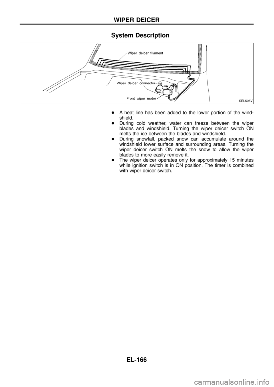
System Description
+A heat line has been added to the lower portion of the wind-
shield.
+During cold weather, water can freeze between the wiper
blades and windshield. Turning the wiper deicer switch ON
melts the ice between the blades and windshield.
+During snowfall, packed snow can accumulate around the
windshield lower surface and surrounding areas. Turning the
wiper deicer switch ON melts the snow to allow the wiper
blades to more easily remove it.
+The wiper deicer operates only for approximately 15 minutes
while ignition switch is in ON position. The timer is combined
with wiper deicer switch.
SEL505V
WIPER DEICER
EL-166
Page 200 of 326
![NISSAN PATROL 1998 Y61 / 5.G Electrical System Workshop Manual System Description
With ignition switch in ON or START position, power is supplied
+through 7.5A fuse [No.
8, located in the fuse block (J/B)]
+to power window relay terminalj
1.
The power window rela NISSAN PATROL 1998 Y61 / 5.G Electrical System Workshop Manual System Description
With ignition switch in ON or START position, power is supplied
+through 7.5A fuse [No.
8, located in the fuse block (J/B)]
+to power window relay terminalj
1.
The power window rela](/manual-img/5/616/w960_616-199.png)
System Description
With ignition switch in ON or START position, power is supplied
+through 7.5A fuse [No.
8, located in the fuse block (J/B)]
+to power window relay terminalj
1.
The power window relay is energized and power is supplied
+through power window relay terminalj
5
+to power window main switch terminalj1,
+to power window sub switch terminalj
5.
MANUAL OPERATION
NOTE:
Numbers in parentheses are terminal numbers, when power window switch is pressed in the UP and DOWN
positions respectively.
Driver side
When the driver side switch in the power window main switch is pressed in the up position, power is supplied
+to driver side power window regulator terminal (j
2,j1)
+through power window main switch terminal (j
9,j8).
Ground is supplied
+to driver side power window regulator terminal (j
1,j2)
+through power window main switch terminal (j
8,j9).
Then, the motor raises or lowers the window until the switch is released.
Passenger side
MAIN SWITCH OPERATION
Power is supplied
+through power window main switch (j
5,j6)
+to front power window sub-switch (j
3,j4).
The subsequent operation is the same as the sub-switch operation.
SUB-SWITCH OPERATION
Power is supplied
+through front power window sub-switch (j
1,j2)
+to passenger side power window regulator (j
2,j1).
Ground is supplied
+to passenger side power window regulator (j
1,j2)
+through front power window sub-switch (j
2,j1)
+to front power window sub-switch (j
4,j3)
+through power window main switch (j
6,j5).
Then, the motor raises or lowers the window until the switch is released.
Rear door
Rear door windows will raise and lower in the same manner as passenger side door window.
AUTO OPERATION
The power window AUTO feature enables the driver to open or close the driver's window without holding the
window switch in the respective position.
When the AUTO switch in the main switch is pressed and released, the driver's window will travel to the fully
open or closed position.
POWER WINDOW LOCK
The power window lock is designed to lock operation of all windows except for driver's door window.
When the lock switch is pressed to lock position, ground of the sub-switches in the power window main switch
is disconnected. This prevents the power window motors from operating.
POWER WINDOW
EL-196