Page 16 of 75
5. Install valve stopper while piston is pushed into cylinder (Modelwith ABS only).
Installation
CAUTION:
+Re®ll with new brake ¯uid ``DOT 3''.
+ Never reuse drained brake ¯uid.
1. Place master cylinder onto brake booster and secure mounting nuts lightly.
2. Torque mounting nuts.
:12-15N zm (1.2 - 1.5 kg-m ,9-11ft-lb)
3. Fill up reservoir tank with new brake ¯uid.
4. Plug all ports on master cylinder with ®ngers to prevent air suction while releasing brake pedal.
5. Have driver depress brake pedal slowly several times until no air comes out of master cylinder.
6. Fit brake lines to master cylinder.
7. Tighten ¯are nuts.
:15-17N zm (1.5 - 1.7 kg-m, 11 - 12 ft-lb)
8. Bleed air. Refer to ``Bleeding Brake System'', BR-4.
SBR168E
SBR169E
MASTER CYLINDER
Assembly (Cont'd)
BR-14
Page 18 of 75
1. Before ®tting booster, temporarily adjust clevis to dimensionshown.
2. Fit booster, then secure mounting nuts (brake pedal bracket to brake booster) lightly.
3. Connect brake pedal and booster input rod with clevis pin.
4. Secure mounting nuts. Speci®cation: 13 - 16 N zm (1.3 - 1.6 kg-m ,9-12ft-lb)
5. Install master cylinder. Refer to ``Installation'' in ``MASTER CYLINDER'', BR-14.
6. Adjust brake pedal height and free play. Refer to ``Adjustment'' in ``BRAKE PEDAL AND BRACKET'',
BR-10.
7. Secure lock nut for clevis.
:16-22N zm (1.6 - 2.2 kg-m, 12 - 16 ft-lb)
8. Bleed air. Refer to ``Bleeding Brake System'', BR-4.
BRAKE BOOSTER
Brake Booster (Cont'd)
BR-16
Page 26 of 75

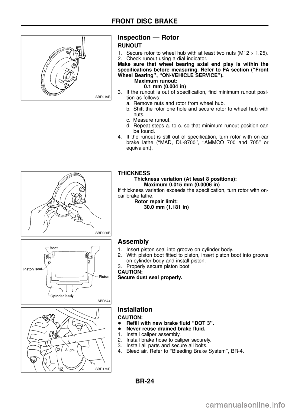
Inspection Ð Rotor
RUNOUT
1. Secure rotor to wheel hub with at least two nuts (M12 ý 1.25).
2. Check runout using a dial indicator.
Make sure that wheel bearing axial end play is within the
speci®cations before measuring. Refer to FA section (``Front
Wheel Bearing'', ``ON-VEHICLE SERVICE'').Maximum runout:0.1 mm (0.004 in)
3. If the runout is out of speci®cation, ®nd minimum runout posi- tion as follows:
a. Remove nuts and rotor from wheel hub.
b. Shift the rotor one hole and secure rotor to wheel hub withnuts.
c. Measure runout.
d. Repeat steps a. to c. so that minimum runout position can be found.
4. If the runout is still out of speci®cation, turn rotor with on-car brake lathe (``MAD, DL-8700'', ``AMMCO 700 and 705'' or
equivalent).
THICKNESS
Thickness variation (At least 8 positions): Maximum 0.015 mm (0.0006 in)
If thickness variation exceeds the speci®cation, turn rotor with on-
car brake lathe. Rotor repair limit:30.0 mm (1.181 in)
Assembly
1. Insert piston seal into groove on cylinder body.
2. With piston boot ®tted to piston, insert piston boot into grooveon cylinder body and install piston.
3. Properly secure piston boot
CAUTION:
Secure dust seal properly.
Installation
CAUTION:
+ Re®ll with new brake ¯uid ``DOT 3''.
+ Never reuse drained brake ¯uid.
1. Install caliper assembly.
2. Install brake hose to caliper securely.
3. Install all parts and secure all bolts.
4. Bleed air. Refer to ``Bleeding Brake System'', BR-4.
SBR019B
SBR020B
SBR574
SBR175E
FRONT DISC BRAKE
BR-24
Page 30 of 75

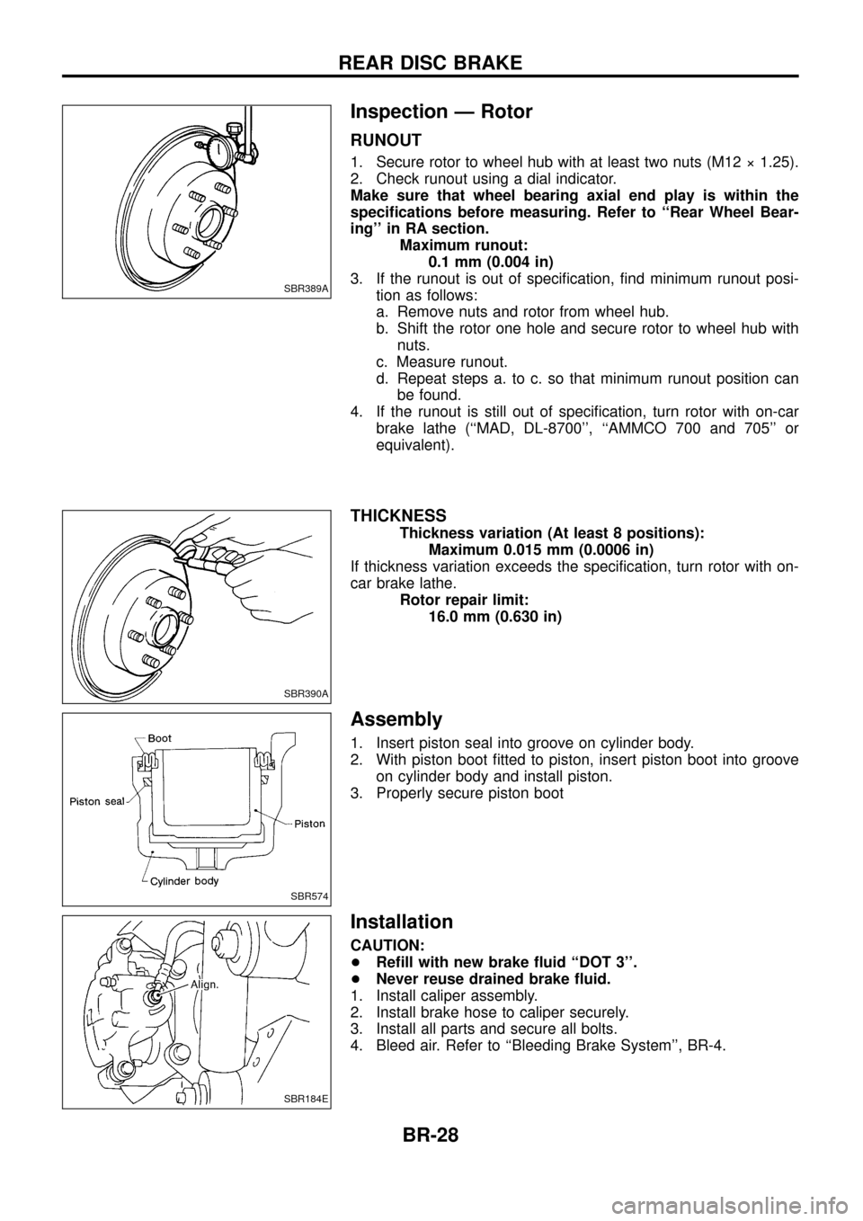
Inspection Ð Rotor
RUNOUT
1. Secure rotor to wheel hub with at least two nuts (M12 ý 1.25).
2. Check runout using a dial indicator.
Make sure that wheel bearing axial end play is within the
speci®cations before measuring. Refer to ``Rear Wheel Bear-
ing'' in RA section.Maximum runout:0.1 mm (0.004 in)
3. If the runout is out of speci®cation, ®nd minimum runout posi- tion as follows:
a. Remove nuts and rotor from wheel hub.
b. Shift the rotor one hole and secure rotor to wheel hub withnuts.
c. Measure runout.
d. Repeat steps a. to c. so that minimum runout position can be found.
4. If the runout is still out of speci®cation, turn rotor with on-car brake lathe (``MAD, DL-8700'', ``AMMCO 700 and 705'' or
equivalent).
THICKNESS
Thickness variation (At least 8 positions): Maximum 0.015 mm (0.0006 in)
If thickness variation exceeds the speci®cation, turn rotor with on-
car brake lathe. Rotor repair limit:16.0 mm (0.630 in)
Assembly
1. Insert piston seal into groove on cylinder body.
2. With piston boot ®tted to piston, insert piston boot into grooveon cylinder body and install piston.
3. Properly secure piston boot
Installation
CAUTION:
+ Re®ll with new brake ¯uid ``DOT 3''.
+ Never reuse drained brake ¯uid.
1. Install caliper assembly.
2. Install brake hose to caliper securely.
3. Install all parts and secure all bolts.
4. Bleed air. Refer to ``Bleeding Brake System'', BR-4.
SBR389A
SBR390A
SBR574
SBR184E
REAR DISC BRAKE
BR-28
Page 52 of 75

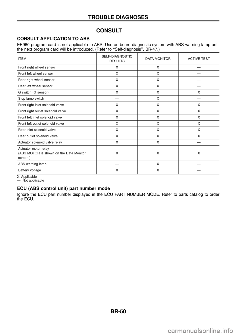
CONSULT
CONSULT APPLICATION TO ABS
EE960 program card is not applicable to ABS. Use on board diagnostic system with ABS warning lamp until
the next program card will be introduced. (Refer to ``Self-diagnosis'', BR-47.)
ITEMSELF-DIAGNOSTIC
RESULTS DATA MONITOR ACTIVE TEST
Front right wheel sensor X X Ð
Front left wheel sensor X X Ð
Rear right wheel sensor X X Ð
Rear left wheel sensor X X Ð
G switch (G sensor) X X X
Stop lamp switch Ð X Ð
Front right inlet solenoid valve X X X
Front right outlet solenoid valve X X X
Front left inlet solenoid valve X X X
Front left outlet solenoid valve X X X
Rear inlet solenoid valve X X X
Rear outlet solenoid valve X X X
Actuator solenoid valve relay X X Ð
Actuator motor relay
(ABS MOTOR is shown on the Data Monitor
screen.) XXX
ABS warning lamp Ð X Ð
Battery voltage X X Ð
X: Applicable
Ð: Not applicable
ECU (ABS control unit) part number mode
Ignore the ECU part number displayed in the ECU PART NUMBER MODE. Refer to parts catalog to order
the ECU.
TROUBLE DIAGNOSES
BR-50