Page 971 of 1501
2 - 10 Amp (Red)
Radio
3 - 10 Amp (Red)
Heater Relay
4 - 10 Amp (Red)
4A/T
5 - 20 Amp (Yellow)
Front & Rear Air Conditioner
6 - 10 Amp (Red)
Turn Signals
7 - 10 Amp (Red)
Meters
8 - 10 Amp (Red)
Horn
9 - 15 Amp (Light Blue)
Wiper
10 - 10 Amp (Red)
Power Window Control
11 - 10 Amp (Red)
Four Wheel Drive System, Overdrive Control (Vehicles With
Automatic Transmission Only)
12 - 15 Amp (Light Blue)
Power Door Locks
13 - 10 Amp (Red)
Doom Light, Clock
14 - 15 Amp (Light Blue)
Backup Lights
15 - 15 Amp (Light Blue)
Stoplights
16 - 25 Amp
Heater
17 - 15 Amp (Light Blue)
Accessory Socket
18 - 10 Amp (Red)
Rear Heater
19 - Spare Fuse
ENGINE COMPARTMENT
Fig. 4: Engine Compartment Fusible Links
Courtesy of Mitsubishi Motor Sales of America.
Page 977 of 1501

MIRRORS - POWER
1998 Mitsubishi Montero
1998 ACCESSORIES & EQUIPMENT
Mitsubishi - Power Mirrors
Eclipse, Galant, Mirage, Montero, Montero Sport, 3000GT
DESCRIPTION & OPERATION
Electric remote control mirrors are controlled by a dual-
control switch mounted on driver's door, dash or center console
depending on model. Left/right switch directs current to desired
mirror. Horizontal/vertical switch directs current to electric motor
in mirror assembly, controlling up/down and left/right adjustment.
Heated mirrors are controlled by defogger relay.
TROUBLE SHOOTING
POWER MIRRORS INOPERATIVE
Check for faulty fuse, faulty power mirror switch or faulty
power mirror motor. See POWER MIRROR FUSE IDENTIFICATION table.
POWER MIRROR FUSE IDENTIFICATION TABLE
������������������\
������������������\
������������������\
������������������\
������������������\
������������������\
�����������
Application Fuse No.
Eclipse ............................................... 13
Galant ................................................. 9
Mirage ................................................. 7
Montero & 3000GT ....................................... 5
Montero Sport .......................................... 8
������������������\
������������������\
������������������\
������������������\
������������������\
������������������\
�����������
COMPONENT TESTS
POWER MIRROR MOTOR TEST
Connect 12-volt power source to mirror connector terminals.
See Figs. 1 -6. Replace mirror as necessary.
Fig. 1: Identifying Power Mirror Operational Test Charts (Eclipse,
Galant, Montero - W/Heater & Montero Sport - W/Heater)
Courtesy of Chrysler Corp.
Page 1029 of 1501

POWER WINDOWS
1998 Mitsubishi Montero
1998 ACCESSORIES & EQUIPMENT
Mitsubishi - Power Windows
Mirage, Montero, Montero Sport & 3000GT
DESCRIPTION & OPERATION
With ignition switch in RUN position, battery voltage is
applied to master power window switch located on driver's door. Master
power window switch provides power and ground for all power window
switches and motors. Master power window switch offers one-touch
operation of driver's window. A solid state control unit, incorporated
in master switch, fully lowers driver's window when switch is
completely depressed. Master switch also includes lock-out feature to
prevent passengers from operating any of the other power window door
switches.
COMPONENT LOCATIONS
COMPONENT LOCATIONS TABLE������������������\
������������������\
������������������\
������������������\
������������������\
������������������\
�����������
Component Location
Power Window Relay ( 1) .......... In Passenger Compartment
Fuse/Relay Block
( 1) - See Fig. 1.
������������������\
������������������\
������������������\
������������������\
������������������\
������������������\
�����������
TROUBLE SHOOTING
POWER WINDOWS INOPERATIVE
Check for faulty fusible link, faulty power window relay or
faulty power window switches. See WIRING DIAGRAMS.
ONE WINDOW FAILS TO OPERATE
If one window does not operate, even if both master and
passenger side power window switches are pressed, check for faulty
master power window switch or power window motor that is inoperative.
If one window does not operate only when either master or passenger
side power window switch is pressed, but does operate when both
switches are pressed, check power window switch that is inoperative.
ONE-TOUCH SWITCH FUNCTION INOPERATIVE
Replace master power window switch.
COMPONENT TESTS
CIRCUIT BREAKER TEST
Press UP switch to fully close window. Continue to press
switch for 10 seconds. Release UP switch and immediately press DOWN
switch. If window begins to open within 60 seconds, circuit breaker is
Page 1030 of 1501

okay. Circuit breaker is part of window motor.
POWER WINDOW RELAY TEST
Mirage & 3000GT
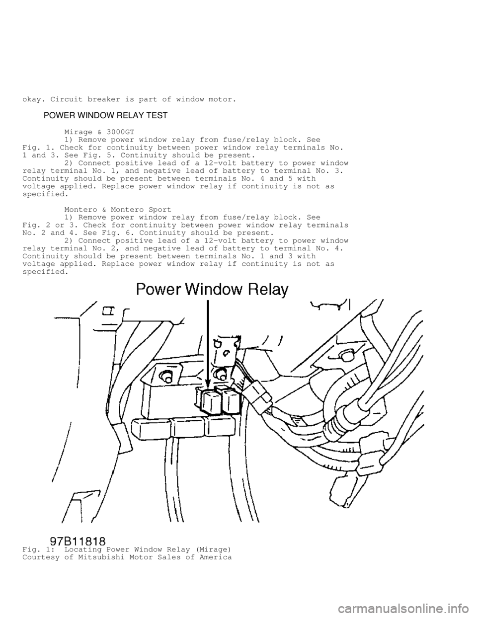
1) Remove power window relay from fuse/relay block. See
Fig. 1 . Check for continuity between power window relay terminals No.
1 and 3. See Fig. 5. Continuity should be present.
2) Connect positive lead of a 12-volt battery to power window
relay terminal No. 1, and negative lead of battery to terminal No. 3.
Continuity should be present between terminals No. 4 and 5 with
voltage applied. Replace power window relay if continuity is not as
specified.
Montero & Montero Sport
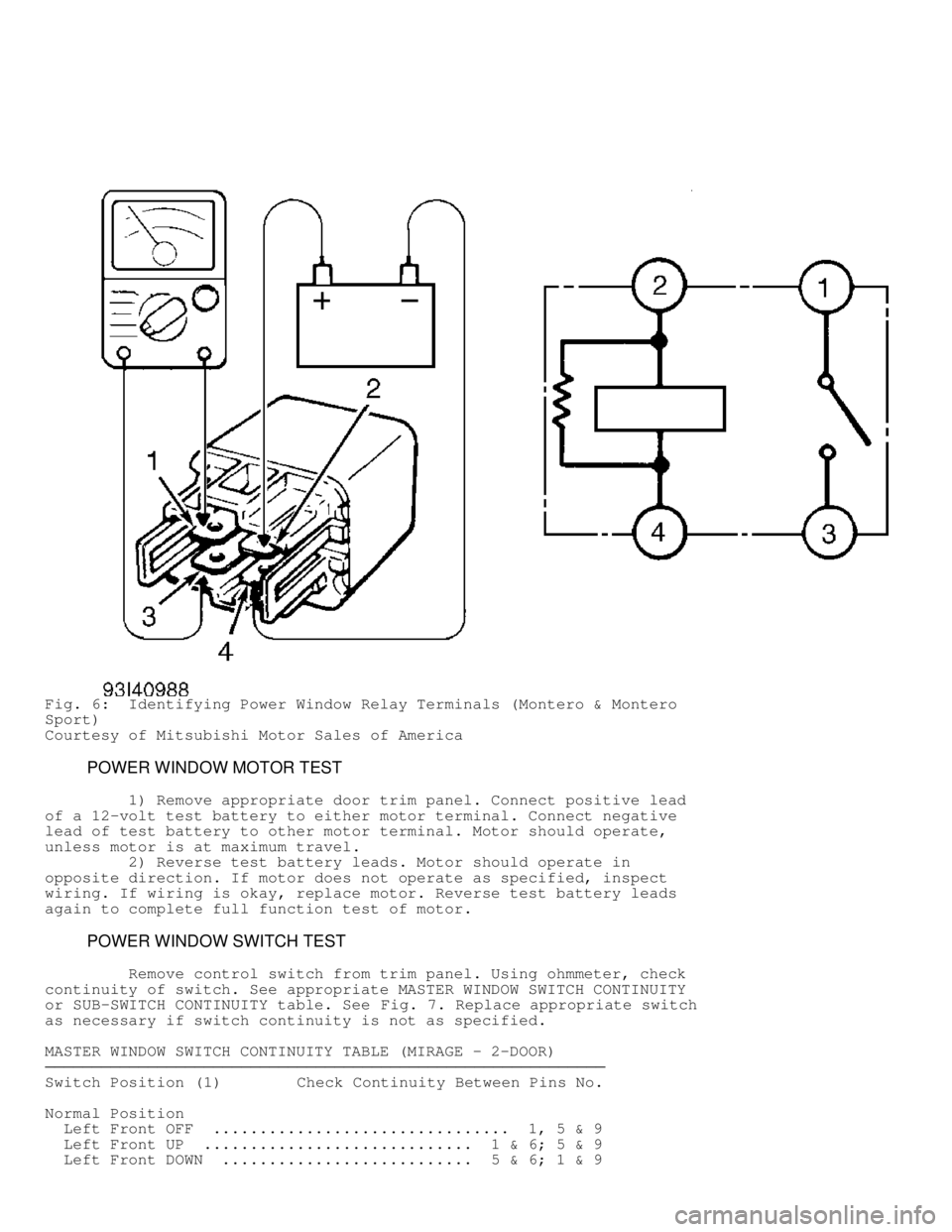
1) Remove power window relay from fuse/relay block. See
Fig. 2 or 3. Check for continuity between power window relay terminals
No. 2 and 4. See Fig. 6. Continuity should be present.
2) Connect positive lead of a 12-volt battery to power window
relay terminal No. 2, and negative lead of battery to terminal No. 4.
Continuity should be present between terminals No. 1 and 3 with
voltage applied. Replace power window relay if continuity is not as
specified.
Fig. 1: Locating Power Window Relay (Mirage)
Courtesy of Mitsubishi Motor Sales of America
Page 1031 of 1501
Fig. 2: Locating Power Window Relay (Montero)
Courtesy of Mitsubishi Motor Sales of America
Fig. 3: Locating Power Window Relay (Montero Sport)
Courtesy of Mitsubishi Motor Sales of America
Page 1032 of 1501
Fig. 4: Locating Power Window Relay (3000GT)
Courtesy of Mitsubishi Motor Sales of America
Fig. 5: Identifying Power Window Relay Terminals (Mirage & 3000GT)
Courtesy of Mitsubishi Motor Sales of America
Page 1033 of 1501

Fig. 6: Identifying Power Window Relay Terminals (Montero & Montero
Sport)
Courtesy of Mitsubishi Motor Sales of America
POWER WINDOW MOTOR TEST
1) Remove appropriate door trim panel. Connect positive lead
of a 12-volt test battery to either motor terminal. Connect negative
lead of test battery to other motor terminal. Motor should operate,
unless motor is at maximum travel.
2) Reverse test battery leads. Motor should operate in
opposite direction. If motor does not operate as specified, inspect
wiring. If wiring is okay, replace motor. Reverse test battery leads
again to complete full function test of motor.
POWER WINDOW SWITCH TEST
Remove control switch from trim panel. Using ohmmeter, check
continuity of switch. See appropriate MASTER WINDOW SWITCH CONTINUITY
or SUB-SWITCH CONTINUITY table. See Fig. 7. Replace appropriate switch
as necessary if switch continuity is not as specified.
MASTER WINDOW SWITCH CONTINUITY TABLE (MIRAGE - 2-DOOR)
������������������\
������������������\
������������������\
������������������\
������������������\
������������������\
�����������
Switch Position (1) Check Continuity Between Pins No.
Normal Position
Left Front OFF ................................ 1, 5 & 9
Left Front UP ............................. 1 & 6; 5 & 9
Left Front DOWN ........................... 5 & 6; 1 & 9
Page 1067 of 1501

SEATS - POWER
1998 Mitsubishi Montero
1998 ACCESSORIES & EQUIPMENT
Mitsubishi - Power Seats
Eclipse, Galant, Montero, 3000GT
DESCRIPTION & OPERATION
Power seat system consists of reversible motors, a control
switch assembly and a wiring harness. Circuit is protected by a
fusible link, located in main relay box in engine compartment.
Power assist adjustments offered are: forward and backward
movement, height adjustment and separately adjusted front or rear seat
tilt. Controls are located on side of seat cushion or on center
console.
COMPONENT LOCATIONS
COMPONENT LOCATIONS TABLE������������������\
������������������\
������������������\
������������������\
������������������\
������������������\
�����������
Component Location
Data Link Connector (DLC) ............ Under Left Of Dash,
Below Steering Column
ETACS-ECU
3000GT ......................... Left Of Steering Column
Seat Adjusting Motors .............. Under Each Front Seat
������������������\
������������������\
������������������\
������������������\
������������������\
������������������\
�����������
COMPONENT TESTS
LIMIT SWITCH/SENSOR
Galant (Driver's Seat)
Disconnect each limit switch harness connector. Operate each
switch to check continuity between specified pins using ohmmeter. See
LIMIT SWITCH CONTINUITY TABLE (GALANT) . See Fig. 1. Replace power seat
adjuster assembly if any switch fails testing.
LIMIT SWITCH CONTINUITY TABLE (GALANT)
������������������\
������������������\
������������������\
������������������\
������������������\
������������������\
�����������
Switch Check Continuity
Position Between Pins No.
Slide Limit Switch
Forward .......................................... 1 & 2
Backward ......................................... 1 & 3
Middle (ON) ................................... 1, 2 & 3
Front & Rear Height Limit Switch
Front Up ......................................... 1 & 3
Front Down ....................................... 1 & 2
Front Middle (ON) ............................. 1, 2 & 3
Rear Up .......................................... 1 & 3
Rear Down ........................................ 1 & 2
Rear Middle (ON) .............................. 1, 2 & 3
������������������\
������������������\
������������������\
������������������\
������������������\
������������������\
�����������