Page 28 of 396

ENGINE – Timing Belt11-22
REMOVAL SERVICE POINTS
�A�TIMING BELT REMOVAL
(1) If the timing belt is to be reused, chalk an arrow mark
on the back surface of the belt so that the belt can be
reinstalled in the same direction.
(2) Place the exhaust camshaft sprocket in a position where
the timing mark for No. 1 cylinder is positioned about
one tooth before the top dead center of the compression
stroke.
Caution
The camshaft sprocket on the exhaust side can turn
very easily because of the valve spring tension. Use
care not to allow your fingers to get caught by the
sprocket.
(3) Loosen the lock nut of the tensioner pulley, then remove
the timing belt.
�B�OIL PUMP SPROCKET REMOVAL
(1) Remove the plug on the left side of cylinder block.
(2) Insert a screwdriver (shank diameter 8 mm) to block the
counterbalance shaft.
(3) Loosen the flange bolt.
(4) Remove the oil pump sprocket.
�C�CRANKSHAFT BOLT LOOSENING
�D�CRANKSHAFT SPROCKET REMOVAL
If it is difficult to remove the sprocket, use the special tool.
Timing mark
Page 31 of 396
ENGINE – Timing Belt11-25
INSTALLATION SERVICE POINTS
�A�CAMSHAFT SPROCKET BOLT TIGHTENING
Using a wrench, hold the camshaft at its hexagon and tighten
the bolt to the specification.
Caution
Locking the camshaft sprocket with a tool damages the
sprocket.
�B�ENGINE SUPPORT BRACKET LEFT
INSTALLATION
Coat the bolts illustrated with sealant before tightening.
Specified sealant: THREEBOND 1207F or equivalent
�C�SEALANT APPLICATION ON SEMI-CIRCULAR
PACKING
Apply sealant to the areas indicated in the illustration.
Specified sealant: THREEBOND 1212D or equivalent
Apply sealant
Apply
sealant 10 mm
10 mm
Cylinder head Semi-circular
packing
Page 40 of 396

ENGINE – Engine Assembly 11- 34
REMOVAL SERVICE POINTS
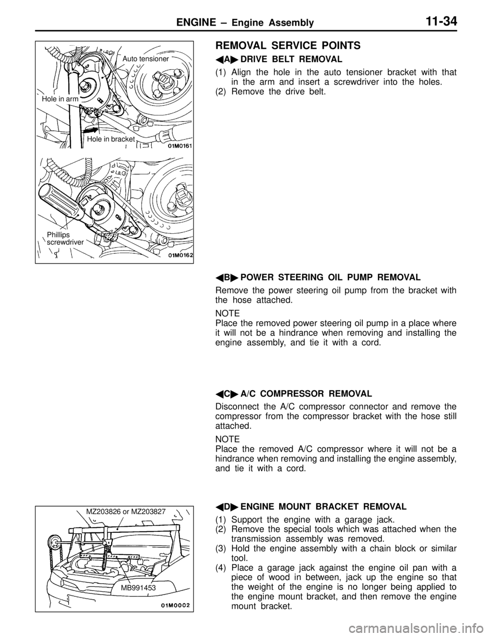
� A� DRIVE BELT REMOVAL
(1) Align the hole in the auto tensioner bracket with that in the arm and insert a screwdriver into the holes.
(2) Remove the drive belt.
� B� POWER STEERING OIL PUMP REMOVAL
Remove the power steering oil pump from the bracket with
the hose attached.
NOTE
Place the removed power steering oil pump in a place where
it will not be a hindrance when removing and installing the
engine assembly, and tie it with a cord.
� C� A/C COMPRESSOR REMOVAL
Disconnect the A/C compressor connector and remove the
compressor from the compressor bracket with the hose still
attached.
NOTE
Place the removed A/C compressor where it will not be a
hindrance when removing and installing the engine assembly,
and tie it with a cord.
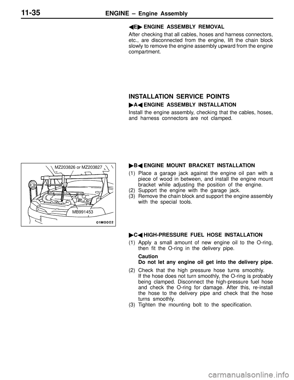
� D� ENGINE MOUNT BRACKET REMOVAL
(1) Support the engine with a garage jack.
(2) Remove the special tools which was attached when the transmission assembly was removed.
(3) Hold the engine assembly with a chain block or similar tool.
(4) Place a garage jack against the engine oil pan with a piece of wood in between, jack up the engine so that
the weight of the engine is no longer being applied to
the engine mount bracket, and then remove the engine
mount bracket.
Phillips
screwdriver
Hole in arm
Auto tensioner
Hole in bracket
MZ203826 or MZ203827
MB991453
Page 41 of 396

ENGINE – Engine Assembly11-3 5
�E� ENGINE ASSEMBLY REMOVAL
After checking that all cables, hoses and harness connectors,
etc., are disconnected from the engine, lift the chain block
slowly to remove the engine assembly upward from the engine
compartment.
INSTALLATION SERVICE POINTS
� A� ENGINE ASSEMBLY INSTALLATION
Install the engine assembly, checking that the cables, hoses,
and harness connectors are not clamped.
� B� ENGINE MOUNT BRACKET INSTALLATION
(1) Place a garage jack against the engine oil pan with a piece of wood in between, and install the engine mount
bracket while adjusting the position of the engine.
(2) Support the engine with the garage jack.
(3) Remove the chain block and support the engine assembly
with the special tools.
� C� HIGH-PRESSURE FUEL HOSE INSTALLATION
(1) Apply a small amount of new engine oil to the O-ring, then fit the O-ring in the delivery pipe.
Caution
Do not let any engine oil get into the delivery pipe.
(2) Check that the high pressure hose turns smoothly. If the hose does not turn smoothly, the O-ring is probably
being clamped. Disconnect the high-pressure fuel hose
and check the O-ring for damage. After this, re-install
the hose to the delivery pipe and check that the hose
turns smoothly.
(3) Tighten the mounting bolt to the specification.
MZ203826 or MZ203827
MB991453
Page 43 of 396
ENGINE LUBRICATION – Lubricants / Engine Oil Cooler12-2
TSB Revision
LUBRICANTS
ItemsCapacity dm3 {�}
Engine oilQuantity in oil filter0.3 {0.3}
Quantity in oil cooler0.16 {0.16}
Total quantity5.1 {5.1}
BrandDIA QUEEN MOTOR OIL (Grade SG or higher); or engine oil in
a can marked with ILSAC certification.
ENGINE OIL COOLER
REMOVAL AND INSTALLATION
Pre-removal and Post-installation Operation
(1) Engine Oil Removal and Refilling
(2) Front Bumper Removal and Installation
(Refer to GROUP 51.)
3
Unit: Nm {kgf�m}
12 {1.2}
39 – 44
{4.0 – 4.5} 29 – 34
{3.0 – 3.5}
2 1
39 – 44
{4.0 – 4.5} 12 {1.2}
12 {1.2}
Removal steps
1. Engine oil cooler
�A�2. Feed hose assembly
�A�3. Return hose assembly
INSTALLATION SERVICE POINT
�A�FEED HOSE ASSEMBLY / RETURN HOSE
ASSEMBLY INSTALLATION
Fit the hose joint positioning tab into the hole in oil cooler
to secure the hose assembly in position.
Page 44 of 396

13-1
FUEL
CONTENTS
MULTIPOINT INJECTION (MPI) 2. . . . . . .
GENERAL INFORMATION 2. . . . . . . . . . . . . . . .
SERVICE SPECIFICATIONS 3. . . . . . . . . . . . . .
SEALANT 3. . . . . . . . . . . . . . . . . . . . . . . . . . . . . . .
SPECIAL TOOLS 4. . . . . . . . . . . . . . . . . . . . . . . .
TROUBLESHOOTING 6. . . . . . . . . . . . . . . . . . . .
ON-VEHICLE SERVICE 30. . . . . . . . . . . . . . . .
1. Idle Position Switch and Throttle Position
Sensor (TPS) Adjustment 30. . . . . . . . . . . . .
2. Fixed SAS Adjustment 30. . . . . . . . . . . . . . . .
3. Basic Idle Speed Adjustment 30. . . . . . . . . . 4. Fuel Pressure Measurement 30. . . . . . . . . . .
5. MPI System Components Layout 31. . . . . .
6. Intake Air Temperature Sensor Check 32. .
7. Engine Coolant Temperature
Sensor Check 32. . . . . . . . . . . . . . . . . . . . . . . .
8. Oxygen Sensor Check 32. . . . . . . . . . . . . . . .
9. Injector Check 34. . . . . . . . . . . . . . . . . . . . . . .
10. Resistor Check 34. . . . . . . . . . . . . . . . . . . . . . .
11. Fuel Pump Relay No.2 Check 35. . . . . . . . .
12. Fuel Pump Resistor Check 35. . . . . . . . . . . . INJECTOR 36. . . . . . . . . . . . . . . . . . . . . . . . . . . .
THROTTLE BODY 37. . . . . . . . . . . . . . . . . . . . .
Page 46 of 396
MPI – Service Specifications / Sealant13-3
SERVICE SPECIFICATIONS
ItemsSpecifications
Basic ignition timing �BTDC5 ± 3
Basic idle speed rpm850 ± 50
Throttle position sensor adjusting voltage mV400 – 1,000
Throttle position sensor resistance kΩ3.5 – 6.5
ISC servo coil resistance (at 20�C) Ω28 – 33
Intake air temperature sensor resistance kΩAt 20�C2.3 – 3.0
At 80�C0.30 – 0.42
Coolant temperature sensor resistance kΩAt 20�C2.1 – 2.7
At 80�C0.26 – 0.36
Fuel pressure
kPa {kgf/cm2}
When vacuum hose is connected230 {2.35}
kPa {kgf/cm2}
When vacuum hose is disconnected289 – 309 {2.95 – 3.15}
Injector coil resistance Ω2 – 3
Amount of injector fuel leak drop/min1 or less
Oxygen sensor output voltage0.6 – 1.0
Fuel pressure control valve coil resistance (at 20�C) Ω28 – 36
SEALANT
ItemSpecified sealant
Coolant temperature sensorDrying sealant: HELMESEAL H-1M [0110513]
NOTE:
Given in [ ] are MITSUBISHI GENUINE PART numbers.
Page 61 of 396

MPI – Troubleshooting13-18
5. SERVICE DATA LIST
Item
No.Inspection
itemInspection contentsNormal condition
11Oxygen
sensorEngine: After having been warmed
up
Air/fuel mixture is made leaner when
When at 4,000 r/min, engine is
suddenly decelerated200 mV or less
Air/fuel mixture is made leaner when
decelerating, and is made richer
when racing.
When engine is suddenly
raced600 – 1,000 mV
Engine: After having been warmed
up
The ox
ygen sensor signal is used to
Engine is idling400 mV or less
(Chan
ges)The oxygen sensor signal is used to
check the air/fuel mixture ratio, and
control condition is also checked by
the ECU.2,500 r/min
(Changes)
600 – 1,000 mV
12Air flow
sensor*
�Engine coolant temperature:
8095�C
Engine is idling17 – 43 Hz
sensor*80 – 95�C
�Lamps, electric cooling fan and
all accessories: OFF
2,500 r/min46 – 86 Hz
all accessories: OFF
�Transmission: NeutralEngine is racedFrequency increases
in response to racing
13Intake air
temperature
sensor
Ignition switch: ON or with engine
runningWhen intake air temperature
is –20�C–20�C
sensorWhen intake air temperature
is 0�C0�C
When intake air temperature
is 20�C20�C
When intake air temperature
is 40�C40�C
When intake air temperature
is 80�C80�C
14Throttle
position
Ignition switch: ONSet to idle position300 – 1,000 mV
position
sensor
Gradually openIncreases in proportion
to throttle opening
angle
Open fully4,500 – 5,500 mV
16Power
supply
voltageIgnition switch: ONSystem voltage
18Cranking
signal Ignition switch: ONEngine: StoppedOFF
g
(ignition
switch-ST)Engine: CrankingON
NOTE
*: When the car is new (distance it travelled is less than 500 km), output frequency of the air flow sensor may
become about 10% higher.